

Page 1
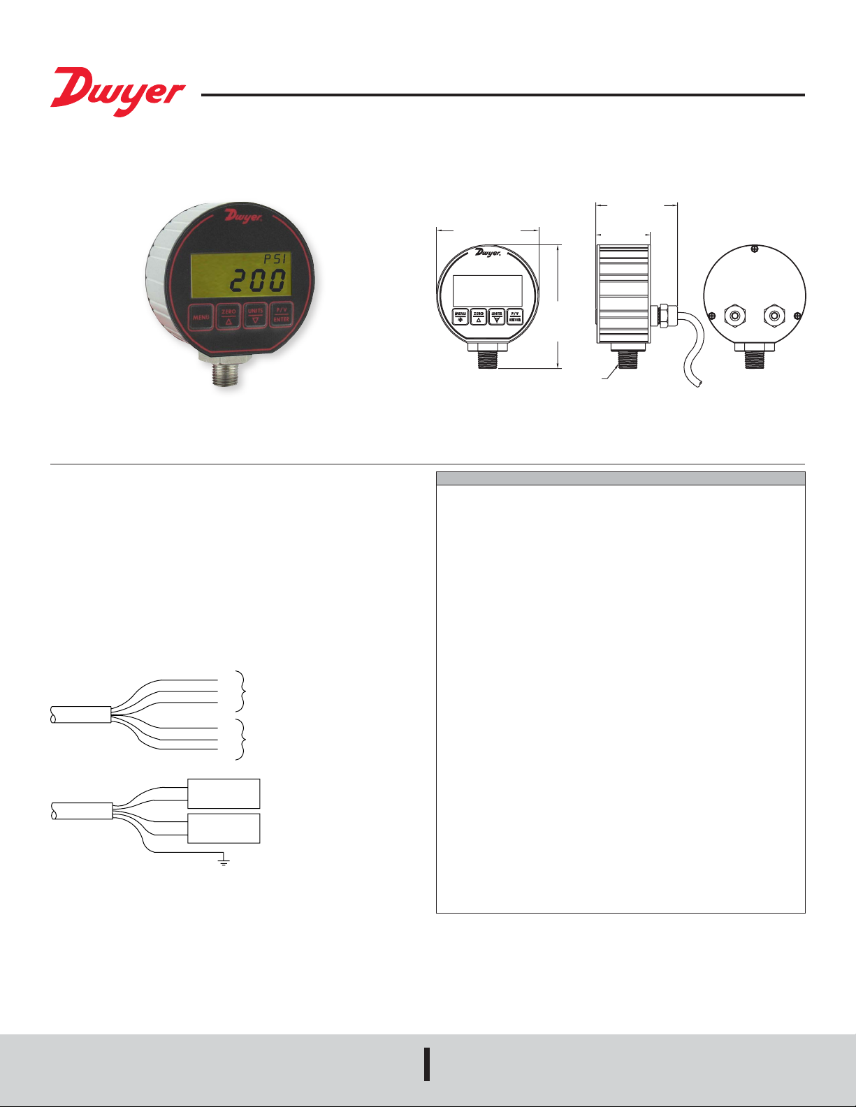
Series DPG-200 Digital Pressure Gage
WHITE
M
2-3/8 [60.45]
®
Specications - Installation and Operating Instructions
Bulletin A-34A
The Series DPG-200 Digital Pressure Gage has a precise ±0.25% full scale
accuracy. The 4 digit digital display will reduce the potential for errors in readings by
eliminating parallax error commonly produced with analog gages. The DPG-200 is
packaged in a durable extruded aluminum case designed to meet NEMA 4X (IP66).
The unit is powered by 12 to 24 VDC/VAC and contains two alarm set points along
with a 4 to 20 mA process output. A four-button keypad allows easy access to features.
These features include backlight, peak and valley, auto zero and conversion of the
pressure units.
INSTALLATION
When installing gage always use 1˝ hex at the base of the housing to tighten the gage
to a mating tting. Do not apply wrench to housing.
WIRING
N.O.
RED
BLACK
ORANGE
BROWN
SHEILD
RED
BLACK
BLUE
ORANGE
GREEN
POWER SUPPLY
10 to 28 VDC
(+)
4 to 20 mA
(-)
RECEIVER
COM
N.C.
N.O.
COM
N.C.
OR VAC
HIGH ALAR
LOW ALARM
3 [76.20]
3-5/8
[91.39]
1/4 NPT
SPECIFICATIONS
DIGITAL GAGE SPECIFICATIONS
Service: Liquids and non-combustible compatible gases.
Wetted Materials: Type 316L SS.
Housing: Black polycarbonate front & back cover, anodized aluminum extruded
housing with recessed grooves, polycarbonate overlay, Buna-N O-rings, 316L SS
sensor construction.
Accuracy: 0.25% FS ±1 least signicant digit. (Includes linearity, hysteresis,
repeatability).
Pressure Limit: 2x pressure range for models 1000 psi; 5000 psi for 3000 psi
range; 7500 psi for 5000 psi range.
Temperature Limits: 0 to 158°F (0 to 70°C).
Process Connection: 1/4˝ male NPT.
Display: 4 digit (.425 H x .234 W digits).
Size: 3.00˝ OD x 1.90 deep (not including cables).
Weight: 8.84 oz (275 g).
SWITCH SPECIFICATIONS
Switch Type: 2 SPDT Form C contacts.
Electrical Rating: 0.5A @ 125 VAC resistive, 1A @ 24 VDC.
Relay Differential: 1 least signicant digit.
Electrical Connections: Two 3 ft (.91 m) cables.
Mounting Orientation: Mount in any position.
Set Point Adjustment: Via menu.
TRANSMITTER SPECIFICATIONS
Temperature Limits: 0 to 158°F (0 to 70°C).
Thermal Effect: Between 70 to 158°F = 0.016%/°F. Between 0 to 70°F =
0.026%/°F.
Power Requirements: 12 to 24 VAC ±20% 50 to 400 HZ, 12 to 24 VDC ±20%.
Output Signal: 4 to 20 mA.
Loop Resistance: 600 Ω maximum.
Power Consumption: 0.8 W max.
Electrical Connections: 2 three foot cables.
Enclosure Rating: Designed to meet NEMA 4X (IP66).
1-5/8
[40.39]
DWYER INSTRUMENTS, INC.
P.O. BOX 373 • MICHIGAN CITY, INDIANA 46360, U.S.A.
Phone: 219/879-8000
Fax: 219/872-9057
www.dwyer-inst.com
e-mail: info@dwyermail.com
Page 2
POWER UP
BUTTON
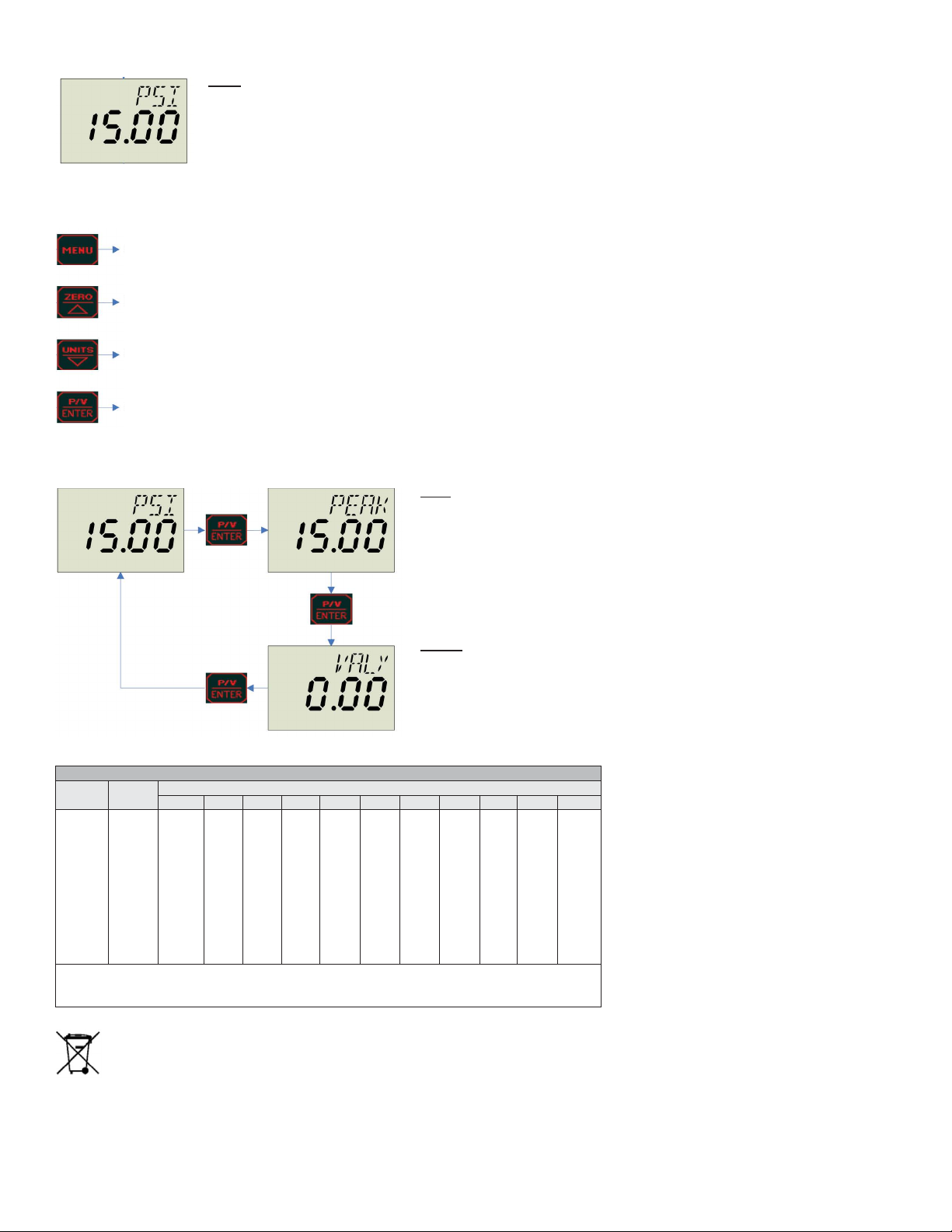
OPERATION
PEAK VALLEY
HOME
• Top line shows units.
• Bottom line shows pressure.
• If pressure is 1% FS below range of instrument the pressure value will alternate UFL on a 1 second interval.
• If pressure is 1% FS above range of instrument the pressure value will alternate with OFL on a 1 second interval.
• Factory set to PSI.
See menu page.
Zeros display if within ±4% F.S. of zero.
See units chart below.
See peak/valley.
PEAK
• Highest pressure since peak and valley was reset.
• Zero button resets both peak and valley to the current pressure.
VALLEY
• Lowest pressure since peak and valley was reset.
• Zero button resets both peak and valley to the current pressure.
UNITS CHART
Model
DPG-200
DPG-202
DPG-203
DPG-204
DPG-205
DPG-206
DPG-207
DPG-208
DPG-209
DPG-210
DPG-211
Range
psi
-14.70-0
15.00
30.00
50.00
100.0
200.0
300.0
500.0
1000
3000
5000
Pressure Ranges
2
kg/cm
bar in Hg ft wc ft sw* kPa oz/in2in wc mbar cm wc mm Hg
-1.033
-1.013
-29.93
-33.94
-33.06
-101.4
-235.2
-407.3
1.055
2.109
3.515
7.03
14.06
21.09
35.15
70.3
210.9
351.5
1.034
2.069
3.448
6.895
13.79
20.69
34.48
68.98
206.9
344.8
30.54
61.08
101.8
203.6
407.2
610.8
1018
2036
6108
34.61
69.21
115.4
230.7
461.4
692.1
1154
2307
6921
33.73
67.45
112.4
224.8
449.7
674.5
1124
2248
6745
103.4
206.9
344.8
689.5
1379
2069
3448
6895
240
480
800
1600
3200
4800
8000
415.2
830.4
1384
2768
5536
8304
-1013
1034
2069
3448
6895
-1034
1055
2109
3515
7031
-760.7
775.7
1551
2586
5172
Compound Ranges Available: DPG-220 Range: 30˝ Hg-0-15 psi; DPG-221 Range: 30˝ Hg-0-30 psi; DPG222* Range: 30˝ Hg-0-45 psi; DPG-223*: Range 30˝ Hg-0-60 psi; DPG-224: 30˝ Hg-0-100 psi.
*feet of seawater @ 4°C
This symbol indicates waste electrical products should not be disposed
of with household waste. Please recycle where facilities exist. Check with
your Local Authority or retailer for recycling advice.
Page 3

MENU
SECURITY
• 1=full access, password is 1110.
• 2=protected, password is 1101.
• Factory set to full access.
• All menus except backlight are protected.
ALARM #1 SETPOINT
• Activates Alarm #1 relay on increase.
• AL1 indicator and alarm #1 relay turned on when pressure is
greater than or equal to setpoint.
ALARM #1 DIFFERENTIAL
• AL1 indicator and alarm #1 relay turned off when pressure is less
than the setpoint minus the differential.
ALARM #2 SETPOINT
• Activates Alarm #2 relay on decrease.
• AL2 indicator and alarm #2 relay turned on when pressure is less
than or equal to setpoint.
ALARM #2 DIFFERENTIAL
• AL2 indicator and alarm #2 relay turned off when pressure is
greater than the setpoint plus the differential.
ALARM #2 INHIBIT
• Prevents low alarm on power up.
• When set to “On” alarm #2 is disabled until the pressure is greater
than the setpoint plus the differential.
• Factory set to ON.
MENU BUTTON OPERATION
Advances menu.
Hold for 1 second to go back to home page.
Increases value - top line of display begins to blink.
Hold for 1 second to increase fast.
Decreases value - top of display beings to blink.
Hold for 1 second to decrease fast.
Stores value - top line of display stops blinking.
If menu pressed before enter button pressed the value is lost.
Page 4

MENU CONTINUED
50
PRESSURE
(psi)
TIME
50
PRESSURE
(psi)
TIME
BACKLIGHT
• Turns backlight on or off.
• Factory set to off.
PROCESS OUTPUT HIGH
• Pressure at which current output is set to 20 mA.
• Factory set to maximum scale.
PROCESS OUTPUT LOW
• Pressure at which current output is set to 4 mA.
• Factory set to minimum scale.
MENU BUTTON OPERATION
Advances menu.
Hold for 1 second to go back to home page.
Increases value - top line of display begins to blink.
Hold for 1 second to increase fast.
MENU BUTTON OPERATION
SPAN ADJUSTMENT
• Display shows pressure using existing span.
• Apply full scale pressure to instrument and hold enter for one
second to acquire new span.
Decreases value - top of display beings to blink.
Hold for 1 second to decrease fast.
Stores value - top line of display stops blinking.
If menu pressed before enter button pressed the value is lost.
AL1S
40
30
20
10
AL1S - AL1D
0
0
AL1D
40
30
20
10
0
AL2S + AL2D
AL2D
AL2S
0
AL1S sets the relay on point, and AL1S - AL1D sets the relay off point. The relay’s output
functions in the direct acting mode, which means the relay activates with an increase
in pressure. In the above graph, an instrument with a 50 psi range has the AL1S set at
40. The relay will turn on at 40 psi increase. The AL1D is set at 30. The relay will turn off
at 10 psi decrease (40 - 30 = 10).
Printed in U.S.A. 2/19 FR# 443202-30 Rev. 2©Copyright 2019 Dwyer Instruments, Inc.
DWYER INSTRUMENTS, INC.
P.O. BOX 373 • MICHIGAN CITY, INDIANA 46360, U.S.A.
AL2S sets the relay on point, and AL2S + AL2D sets the relay off point. The relay’s output
functions in the reverse acting mode, which means the relay activates with a decrease
in pressure. In the above graph, an instrument with a 50 psi range has the AL2S
relay turn on at 10 psi decrease. The AL2D is set at 30. The relay will turn off at 40 psi
increase (10 + 30 = 40).
Phone: 219/879-8000
Fax: 219/872-9057
www.dwyer-inst.com
e-mail: info@dwyermail.com
 Loading...