

Dwyer Instruments DPG-100 Series, DPG-102, DPG-100, DPG-100C, DPG-103 Operating Instructions Manual
...Page 1
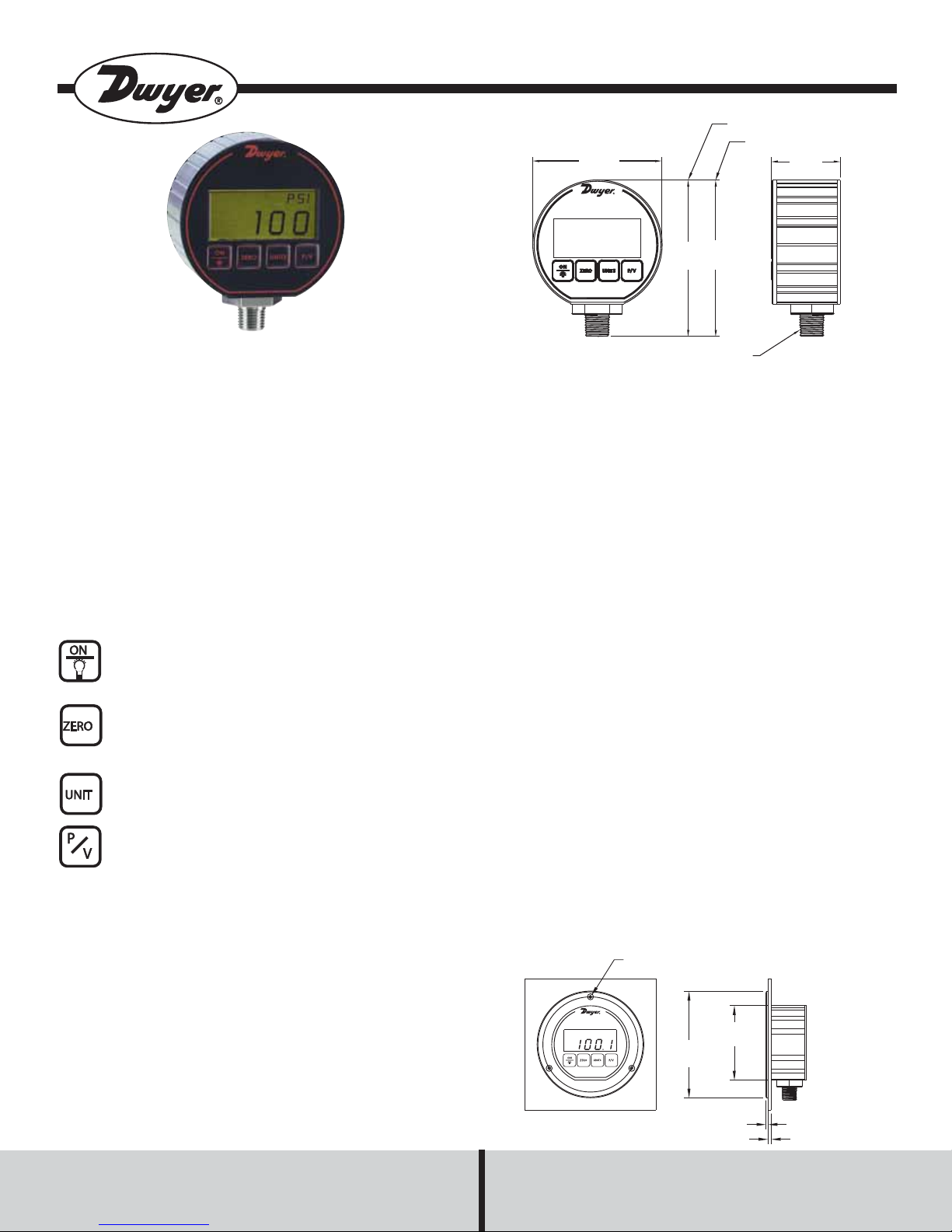
Series DPG-100 Digital Pressure Gage
Specifications - Installation and Operating Instructions
STANDARD RANGES
3
[76.20]
3-3/4
3-5/8
[95.25]
[91.39]
Bulletin A-34
CERAMIC RANGES
1-5/8
[40.39]
The Series DPG-100 Digital Pressure Gage has a precise +/- 0.25%
full scale accuracy. The 4 digit digital display will reduce the potential for
errors in readings by eliminating parallax error commonly produced with
analog gages.
The DPG-100 is packaged in a durable extruded aluminum case
designed to meet NEMA 4/4X. The unit is battery powered and has an
auto-shut off to conserve battery life. A four button key pad allows easy
access to features without the need to work through complex menus or
difficult key combinations. These features include backlight, peak and
valley, auto zero and conversion of the pressure units. Readings may be
converted to various engineering units. See reverse page for available
units.
DPG Quick Start Button Operation
For complete detailed instructions on the four button operation see the
Operation Chart provided on back.
On/Backlight: Push to turn on; Press again for backlight.
Press and hold for 5 seconds to turn unit off.
Zero: Zeros the display - Push & hold for 2 seconds to zero
the display. If after pressing zero the display does not re-zero,
the unit is no longer meeting specified accuracy and should be
sent back to the factory for calibration. Do not use the zero
button when pressure is applied.
Units: Scroll (see next page for Model/Range Chart).
P/V: Peak recorded reading retrieved by initial push of button;
push again retrieves the valley or lowest value recorded.
INSTALLATION
When installing gage always use 1˝ hex at the base of the housing to
tighten the gage to a mating fitting. Do not apply wrench to housing.
1/4 NPT
Service: Liquids and combustible
compatible gases (for FM listings
see agency approvals below).
Wetted Materials: Type 316L SS;
Ceramic Ranges: Type 316L SS,
ceramic, fluoroelastomer.
Housing Materials: Black polycarbonate front & back cover, anodized
aluminum extruded housing with
recessed grooves, polycarbonate
overlay,Buna-N O-Rings, 316L SS
sensor construction.
Accuracy: 0.25% full scale;
Ceramic Ranges: 0.5% full scale; ±
1 least significant digit @ 70°F
(21°C) . (Includes linearity, hysteresis, repeatability).
Pressure Limit: 2x pressure range
for models ≤1000 psi;5000 psi for
3000 psi range;7500 psi for 5000
psi range.
Enclosure Rating: Designed to
meet NEMA 4/4X (IP65).
Temperature Limits: 0 to130°F
(-18 to 55°C).
Thermal Effect: Between 70 to
130°F is 0.016%/F; Between 32 to
70°F is0.026%/F; Between 10 to
32°Fis 0.09%/F; Between 0 to
10°Fis 0.50%/F.
*Note: Gages with ceramic sensor are not CE and FM approved.
Size: 3.00˝ OD x 1.90 deep (max).
Process Connection: 1/4˝ male
NPT.
Weight: 8.84 oz (275 g).
Display: 4 digit (.425 H x .234W
digits).
Sample Rate: 2 sec.
Power Requirements: Two AAA
batteries.
Battery Life: 2000 hours typi-cal;
low battery indicator.
Auto Shut-Off: Gage: 60 minute
auto shut-off. Auto shut-off may be
disengaged; Backlight: 2 minute
auto shut-off.
Agency Approvals: FM approved
to be intrinsically safe for Class I,
Division I, Groups A,B, C and D, for
ranges 0-15 to0-3000 psi. CE EMC
Directive:
EN 61000-4-2
EN 61000-4-3 & ENV50204
EN 61000-6-2
EN 61000-6-4
EN 55011.
WARNING: DO NOT pressurize DPG over maximum allowable pressure
limits. Extreme damage can occur if limits are exceeded (see Pressure
Limit under Specifications). An overflow “OFL” designator will flash to
acknowledge that the gage’s pressure range has been exceeded.
PANEL MOUNT OPTION
Drill a 3-1/4˝ (82.55) diameter hole in a panel, locate three mounting
holes for a #6 screw 120° apart on a 3-58˝ (92.08) bolt circle.
MAINTENANCE
A “LOW BAT” descriptor indication will appear on the display when batteries need to be replaced.
(3) MOUNTING HOLES FOR #6 FLAT HEAD SCREW
EQUALLY SPACED ON A 3-5/8 (92.08) B.C.
Battery Replacement: Remove the three screws on backplate. Lift back-
4-1/16
(103.19)
3-1/4 (82.55)
HOLE IN PANEL
plate off by hand. Replace batteries per polarity indicators. To reassemble, ensure O-Ring seats into housing evenly and press until seated
completely. Replace screws.
WARNING: Substitution of components may impair intrinsic safety.
Batteries must be changed in a non-hazardous location only. DO NOT
mix batteries from different manufacturers. DO NOT mix old batteries
with new batteries.
DWYER INSTRUMENTS, INC.
Phone: 219/879-8000 www.dwyer-inst.com
5/64
(1.98)
P.O. Box 373 • Michigan City, IN 46361-0373, U.S.A. Fax: 219/872-9057 e-mail: info@dwyer-inst.com
9/32 (7.14) MAX
PANEL THICKNESS
Page 2
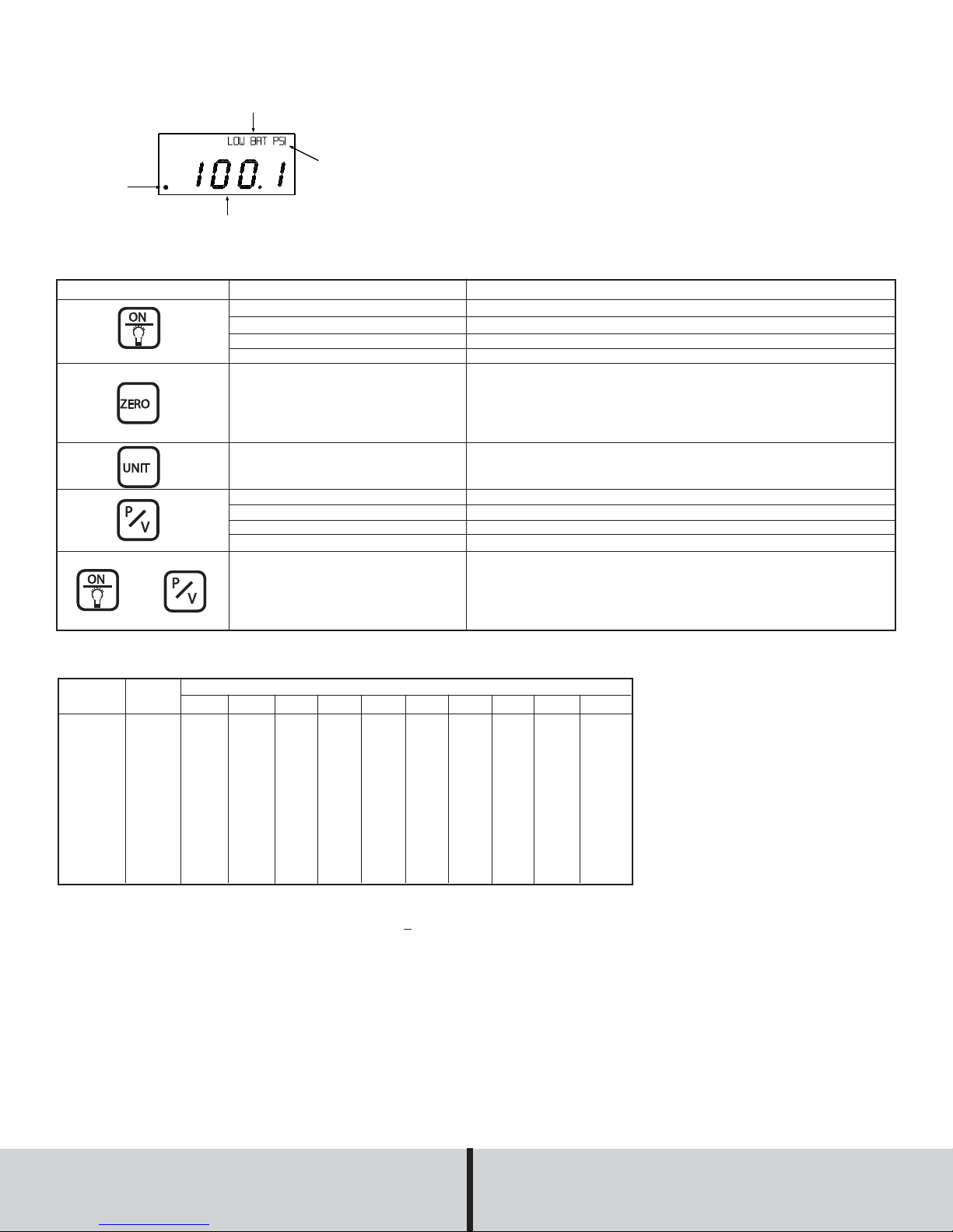
LOW BATTERY INDICATION
UNITS
PRESSURE READING
AUTO SHUT-OFF
INDICATOR
DPG-100 DISPLAY
DPG Button Operation
Button Operation Action
Press and hold ON button
While gage is on press ON button
While backlight is on press ON button
While gage is on, press and hold ON button 5 seconds for unit to turn off.
With no pressure applied to the gage, press and hold ZERO button until
display flashes
If gage will not zero, then gage is no longer meeting specified accuracy
and should be sent back to the factory for recalibration
NOTE: Gage is not to be zeroed while pressure is applied
Press UNIT button to change units on gage (Not all units are available for
each range, please refer to model/range chart located below for available
units)
Press P/V button to read peak (highest pressure) measurement
Press P/V button again to read valley (lowest pressure) measurement
Press and hold P/V button to reset peak and valley
Press ON button to exit peak/valley
Auto shut-off will turn off an idle gage after 60 minutes. To disengage
auto shut-off, press and hold ON button, then press and hold P/V button.
A decimal will blink in the lower left hand corner of the display to indicate
the auto-shut off is turned off. To turn on auto shut-off, repeat above procedure until decimal point stops blinking
plus
Turn Unit On
Turn Backlight On (Auto Shut-Off: 2 Min)
Turn Backlight Off
Turn Unit Off
Zero Gage
Unit Selection
View Peak
View Valley
Reset Peak & Valley
Exit Peak & Valley
Disengage Auto Shut-Off
Model/Range Chart
Model
Number
DPG-100*
DPG-102
DPG-103
DPG-104
DPG-105
DPG-106
DPG-107
DPG-108
DPG-109
DPG-110
DPG-111*
Compound Ranges available: DPG-120* Range: 30˝ Hg-0-15 psi; DPG-121* Range: 30˝ Hg-0-30 psi; DPG-122* Range: 30˝ Hg-0-45 psi; DPG-123*:
Range 30˝ Hg-0-60 psi; DPG-124*: 30˝ Hg-0-100 psi.
*Optional ceramic sensor available. Add “C” to the range (Ex. DPG-100C).
Range
psi
-14.70-0
15.00
30.00
50.00
100.0
200.0
300.0
500.0
1000
3000
5000
kg/cm
-1.033
1.055
2.109
3.515
7.03
14.06
21.09
35.15
70.3
210.9
351.5
2
bar
-1.013
1.034
2.069
3.448
6.895
13.79
20.69
34.48
68.98
206.9
344.8
in Hg
-29.93
30.54
61.08
101.8
203.6
407.2
610.8
1018
2036
6108
Pressure Ranges
ft wc
-33.94
34.61
69.21
115.4
230.7
461.4
692.1
1154
2307
6921
kPa
-101.4
103.4
206.9
344.8
689.5
1379
2069
3448
6895
oz/in
-235.2
240
480
800
1600
3200
4800
8000
2
in wc
-407.3
415.2
830.4
1384
2768
5536
8304
mbar
-1013
1034
2069
3448
6895
cm wc
-1034
1055
2109
3515
7031
mm Hg
-760.7
775.7
1551
2586
5172
©Copyright 2009 Dwyer Instruments, Inc. Printed in U.S.A. 8/09 FR# 18-443202-04 Rev. 9
DWYER INSTRUMENTS, INC.
P.O. Box 373 • Michigan City, IN 46361-0373, U.S.A. Fax: 219/872-9057 e-mail: info@dwyer-inst.com
Phone: 219/879-8000 www.dwyer-inst.com
 Loading...