

Page 1

Bulletin B-32
Series DH Digihelic®Differential Pressure Controller
Specifications - Installation and Operating Instructions
DWYER INSTRUMENTS, INC.
P.O. BOX 373 • MICHIGAN CITY, IN 46361, U.S.A. Fax: 219/872-9057 e-mail: info@dwyer-inst.com
Phone: 219/879-8000 www.dwyer-inst.com
www.GlobalTestSupply.com
Page 2

DIMENSIONS
3-19/32
[91.28]
4-1/2
[114.30]
1-3/4
[44.45]
1/2
4-1/2
[114.30]
[12.70]
Face Designed to Meet NEMA 4X (IP66)
PANEL CUT OUTS
Horizontal
3.620 in. + 0.032 - 0.0
(92.00 mm + 0.8 - 0.0)
1.772 in. + 0.024 - 0.0
(45.00 mm + 0.6 - 0.0)
1-15/16
[49.21]
3-25/32
[96.04]
1
www.GlobalTestSupply.com
Page 3

SPECIFICATIONS
Service: Air and non-combustible, compatible gases.
Wetted Materials: Consult factory.
Housing Material: ABS plastic, UL approved 94-V-0.
Accuracy: ±0.5% at 77°F (25°C) including hysteresis and repeatability (after 1 hour
warm-up).
Stability: < ±1% per year.
Pressure Limits: Ranges ≤ 2.5 in. w.c. = 2 psi
5˝: 5 psi; 10˝: 5 psi; 25˝: 5 psi; 50˝: 5 psi; 100˝: 9 psi.
Temperature Limits: 32 to 140°F (0 to 60°C).
Compensated Temperature Limits: 32 to 140°F (0 to 60°C).
Thermal Effects: 0.020%/°F (0.036/°C) from 77°F (25°C).
Power Requirements:
High Voltage Power = 100 to 240 VAC, 50 to 400 Hz or 132 to 240 VDC.
Low Voltage Power = 24 VDC ±20%.
Power Consumption:
Low Voltage Power = 24 VDC - 130 mA max.
High Voltage Power = 100 to 240 VAC, 132 to 240 VDC - 7VA max.
Output Signal: 4-20 mA DC into 900 ohms max.
Zero & Span Adjustments: Accessible via menus.
Response Time: 250 ms (dampening set to 1).
Display: 4 digit LCD 0.4˝ height LED indicators for set point and alarm status.
Electrical Connections: Screw terminals.
Process Connections: Compression fitting for use with 1/8˝ ID tubing x 1/4˝ OD
tubing (3.175 mm ID x 6.35 mm OD).
Enclosure Rating: Face designed to meet NEMA 4X (IP66).
Mounting Orientation: Mount unit in horizontal plane.
Size: 1/8 DIN. Panel Cutout: 1.772 x 3.620 in (45 x 92 mm).
Weight: 14.4 oz (408 g).
Serial Communications: Modbus® Protocol RTU, RS485, 9600 Baud.
Agency Approvals: UL Listed, CUL Listed File No. E83725
CE EMC and Low Voltage Directives:
EN61000-4-2
EN61000-4-3*
EN61000-4-4
EN61000-4-5
EN61000-4-6
EN61000-4-11
EN55011
EN601010
* Models DH-001 through DH-004, DH-011 through DH-014 pass criteria B. All others pass criteria A.
Switch SPECIFICATIONS
Switch Type: 2 SPDT relays.
Electrical Rating: 8 Amps at 240 VAC resistive.
Set Point Adjustment: Adjustable via keypad on face.
2
www.GlobalTestSupply.com
Page 4

WIRING
2020
1919
1818
1717
1616
1515
1414
1313
1111
1212
1010
9 8
7
6
5
4
3
2
1
21
21
2222
2323
2424
C
C
N/CN/C
N/CN/C
N/ON/O
N/O
N/O
SP1
RELAY
SP1
RELAY
SP2 OR
ALARM
RELAY
SP2 OR
ALARM
RELAY
3/8A 250VAC
MEDIUM LAG
3/8A 250VAC
MEDIUM LAG
100-240 VAC or
132-240 VDC POWER
100-240 VAC or
132-240 VDC POWER
NOTE1NOTE1
A
B
_
+
RS485 SERIAL
COMMUNICATION
RS485 SERIAL
COMMUNICATION
_
+
24 VDC POWER24 VDC POWER
REMOTE RESET
SWITCH
REMOTE RESET
SWITCH
NOTE 1
NOTE 1
4-20mA
transmitter
output
4-20mA
transmitter
output
Device receiving 4-20mA
signal. Check specifications
of this device for input load
resistance. Typical 250 to
600 OHMS, 900 OHMS
maximum
signal. Check specifications
of this device for input load
resistance. T
600 OHMS, 900 OHMS
maximum
_
_
+
+
_
+
High Pressure PortHigh Pressure Port
Low
Pressure
Port
Low
Pressure
Port
WIRING
NOTES:
WARNING
If Digihelic®is powered by 24 VDC, the device receiving the 4-20 mA transmitter
output MUST NOT share a common ground with the 24 VDC supply or damage
to the Digihelic®will result.
1. The instrument may be powered from the AC line or 24 VDC. Do not wire AC
line terminals 4-5 and 24 VDC terminals 14-15 at the same time or damage to
the unit will result.
2. For supply connections, wire in accordance with an equivalent national standard
or code. Use copper conductors only rated for at least 75°C.
3. Terminals 11-15, 18 and 20 are rated CLASS 2.
4. ISOLATION:
Relays - 1500 VAC to all other inputs and outputs.
AC Line Power (terminals 4-5) - 1500 VAC to all other inputs and outputs.
RS485 output - 500 VAC to all other CLASS 2 wiring.
The 24 VDC Power, 4-20 mA transmitter, and Remote Reset Switch share
a common ground.
5. The Remote Reset Switch must be a dry contact switch.
6. Shielded cable is required for RS485 wiring.
www.GlobalTestSupply.com
3
Page 5

It is not necessary to remove the control chassis from the housing for
20
19
18
17
16
15
14
13
12
10
9 8
7
6
543
2
1
21
22
23
24
20
19
18
17
16
15
14
13
12
10
9 8
7
6
543
2
1
21
22
23
24
20
19
18
17
16
15
14
13
12
10
9 8
7
6
543
2
1
21
22
23
24
_
_
_
+
+
+
SHIELD
SHIELD
TIE SHIELD TO EARTH GROUND
TO RS232 TO
RS485 CONVERTER
120 OHM
RESISTOR
LAST UNIT ON RS485 BUSS
WIRE NUT
THE 120 OHM RESISTOR
IS USUALLY ONLY
NECESSARY FOR LONG
WIRE RUNS.
installation. If the control chassis is removed from the housing, you
must follow industry standard practice for control and protection
against Electro-Static Discharge (ESD). Failure to exercise good ESD
C
practices may cause damage to the control.
Wiring to housing terminals while chassis is removed may cause distortion of the internal connector and possible damage to the connector when the chassis is reinstalled. It is strongly recommended that
the control housing be wired with the chassis installed.
INSTALLATION
Mount the instrument in a location that will not be subject to excessive temperature,
shock or vibration. All models are designed for mounting in an enclosed panel.
Select the position desired for the instrument on the panel. Prepare the panel by cutting and deburring the required opening.
From the front of the panel, slide the instrument through the cut out. The housing
gasket should be against the housing flange before installing.
From the rear of the panel slide the mounting collar over the housing. Hold the housing with one hand and using the other hand, push the collar evenly against the panel
until the springs are compressed. The ratchets will hold the mounting collar and
housing in place.
DIGIHELIC® CONTROLER RS485 WIRING
- RS485 WIRING TO DAISY CHAIN INSTRUMENTS ON THE
UP TO 128 UNITS MAY BE DAISY CHAINED
TO RS232 TO
RS485 CONVERTER
10
23
24
19
16
17
18
TIE SHIELD TO EARTH GROUND
20
15
14
SHIELD
13
21
22
111112
WIRE NUT
10
23
24
19
20
18
www.GlobalTestSupply.com
RS485 BUSS
LAST UNIT ON RS485 BUSS
10
21
23
22
16
17
15
13
14
SHIELD
4
24
111112
19
20
16
17
15
18
THE 120 OHM RESISTOR
IS USUALLY ONLY
NECESSARY FOR LONG
WIRE RUNS.
14
13
120 OHM
RESISTOR
21
22
111112
Page 6

SP1
SP2
ALHI
ALLO
SP/AL
RST
MENU
E
X1K
MULTIPLIER DESCRIPTOR
MULTIPLIER DESCRIPTOR
VISIBLE WITH SO
ME VELOCITY
AND FLOW RANGE
FRONT PANEL
PRESSURE
VALUE
UNITS
ALARM
DESCRIPTOR
SP2
DESCRIPTOR
SP1
DESCRIPTOR
SP/ALSP/AL
SP/AL
MENUMENU
SP/AL
MENU
SP/AL
MENU
SP/AL
MENU
E
SP/AL
MENU
E
RSTRST
VISIBLE WITH S
AND FLOW RANGE
SP1
DESCRIPTOR
SP2
DESCRIPTOR
ME VELOCITY
FRONT PANEL
X1K
SP1
SP2
SP/AL
MENU
KEY FUNCTIONS
ALLO
ALHI
RST
PRESSURE
VALUE
UNITS
ALARM
DESCRIPTOR
HOME POSITION FUNCTION
Sequences the display
SP/AL
through SET POINT and
ALARM settings
Allows access to the
MENU
UP
ARROW
DOWN
ARROW
ENTER
RESET
Clears or resets an Alarm
(alarm set for manual
menus
Displays full scale
range of unit
MAIN MENU FUNCTION
Return to home
position
Return to home
position
Sequences through
menus
Sequences through
menus
Enter into SUB MENU
reset)
5
www.GlobalTestSupply.com
SUB MENU FUNCTION
Return to home position
Return to previous menu
Increments a value
Decrements a value
Changes a value or
setting. Press ENTER
and display will blink.
Adjust with UP or DOWN
arrows. Press ENTER to
store. Display will stop
blinking.
Peak/Valley SUB
MENU resets display to
present value.
Page 7

SETTING SET POINTS AND ALARMS
SP/AL
SP/AL
SP/AL
SP/AL
SP/AL
SP/AL
SP/AL
SP/AL
SP/AL
SP/AL
SP/AL
SP/AL
SP/AL
Visible when
Visible when
Visible when
mode =
mode =
mode =
CONTROL MODE
CONTROL MODE
CONTROL MODE
PRESSUREPRESSURE
0
0
TIME
TIME
0.20.2
0.40.4
0.60.6
0.80.8
1.0
(in. w.c.)
SP/ALSP/AL
The hot key provides direct access to the Set Point and Alarm MENU. The
Set Point and Alarm MENUS that are displayed are based upon the Control (CtrL)
SUB MENU.
CONTROL MODE
SP/AL
SP/AL
SP/AL
CONTROL MODE
SP/AL
SP/AL
SP/AL
SP/AL
SP/AL
CONTROL MODE
SP/AL
SP/AL
SP/AL
SP/AL
SP/AL
Visible when
Visible when
Visible when
mode =
mode =
mode =
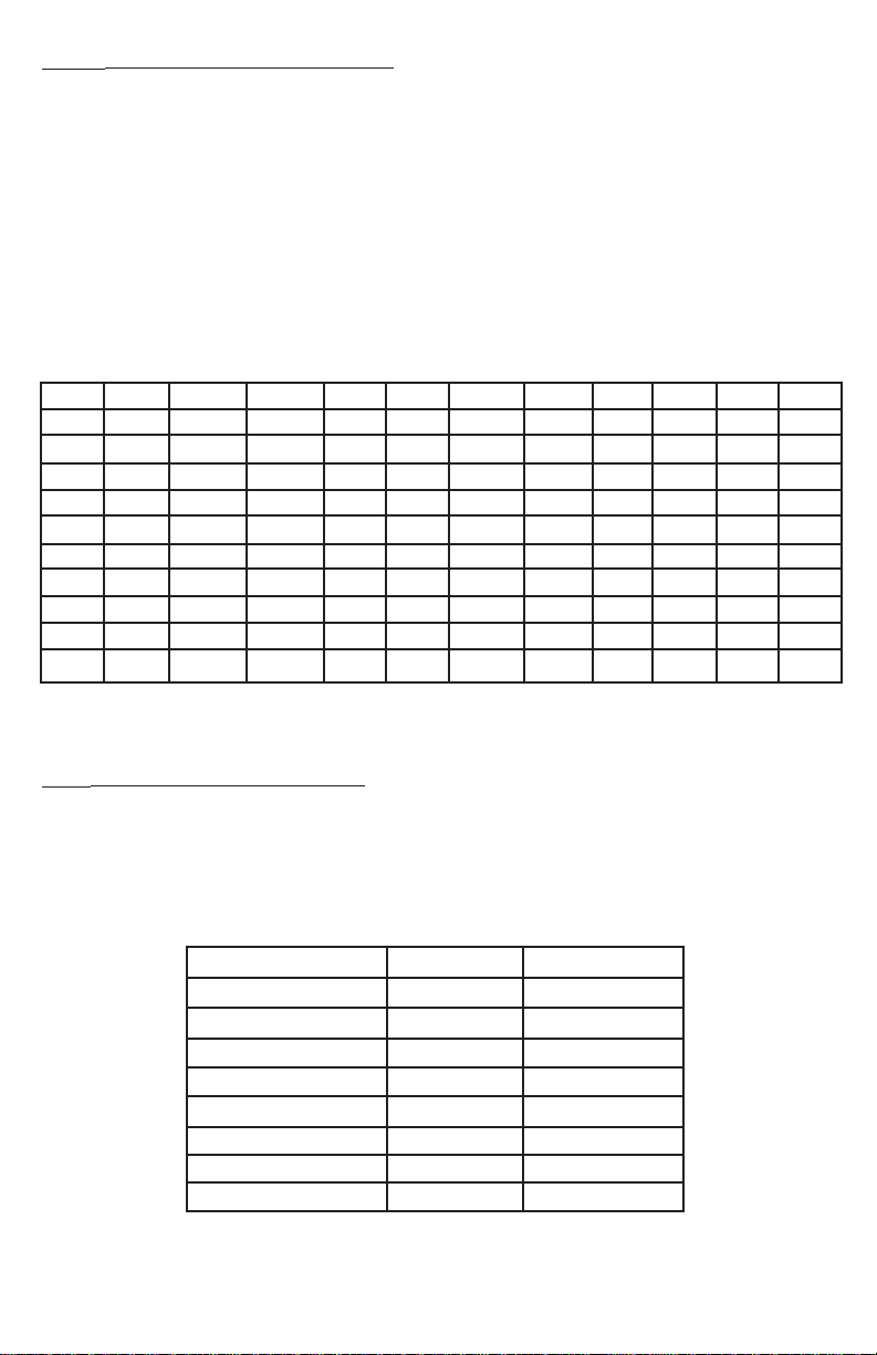
SET POINT ADJUSTMENT
Adjusting the Digihelic®Controller Set Points is quick and simple. Instead of setting
a set point and deadband, simply adjust
SP1L
on point, and then adjust
or
SP2L
SP1H
or
SP2H
for the desired relay turn
for the desired relay turn off point.
In the above graph, an instrument with a 1.0˝ range would have the SP1 relay turn
on at 0.8˝ and off at 0.4˝.
turn off point. The relays outputs normally function in the direct acting mode, which
means the relays turn on with an increase in pressure. SP1 may be configur ed to act
as a reverse acting relay (refer to the 1SP SUB MENU setting, page 15). When set
for reverse acting,
ON point. SP2 is always direct acting.
SP1H
SP1H
www.GlobalTestSupply.com
sets the relay turn on point, and
sets the relay turn OFF point, and
6
SP1L
SP1L
sets the relay turn
sets the relay
Page 8

MENU MAP
MENU MAP
CONTINUED
SETTINGS
SP/AL
MENU
SP/AL
MENU
SP/AL
MENU
E
SP/AL
MENUMENU
MAIN MENUS SUB MENUS
SETTINGS
MENUS
UNAVAILABLE
FOR
BI-DIRECTIONAL
RANGES AND
RANGES ABOVE
25 IN. W.C.
CONTINUED
7
www.GlobalTestSupply.com
Page 9

CONTINUED
SETTINGS
MAIN MENUS SUB MENUS
SP/AL
MENU
SP/AL
MENU
SP/AL
MENU
E
SP/AL
MENUMENU
SETTINGS
CONTINUED
8
www.GlobalTestSupply.com
Page 10

MAIN MENUS SUB MENUS
SETTINGS
SP/AL
MENU
SP/AL
MENU
SP/AL
MENU
E
SP/AL
MENUMENU
Menus present only
in pressure operation
9
www.GlobalTestSupply.com
Page 11

Main Menu Selections (Upper Right Display Reads
MENU
)
SECr
OPEr
OUt
d.S
AdU
Security - Lock out access to Set Point and Alarm settings, or lock out
access to all settings.
Operation - Selection of Pressure, Velocity or Flow and corresponding
engineering units.
Output - Select a Single Set Point, 2 Set Points, or a Set Point and an
Alarm mode of operation.
Display - Monitor and adjust display related settings: Peak, Valley, display
resolution, % output and dampening.
Advanced functions - Modify advanced function parameters, transmitter
output scaling, Modbus
Maintenance Set Point settings and calibration.
®
Protocol communication settings,
10
www.GlobalTestSupply.com
Page 12
MAIN MENUS and SUB MENUS
Units visible, so unit
is presently set to
measure pressure
is presently set to
measure pressure
Units not visibleUnits not visible Units not visibleUnits not visible
SECr
OPEr
The
The SUB MENUS are:
(Security) MAIN MENU
SECr
The password values shown in the table cannot be altered, so retain a copy
of these pages for future reference.
is the only SUB MENU in the security MENU. When the security
SUB MENU is selected, the present security level is displayed in the
upper right hand display. To change the security level, adjust the
number displayed to the number shown in the following table for the
desired security level.
Security Level
Displayed
1
2
3
4
Access
All menus access
Menu Access
SP/AL Locked
SP/AL Access
Menus Locked
All settings locked
Password
Value to Enter
10
70
90
111
(Operation) MAIN MENU
OPEr
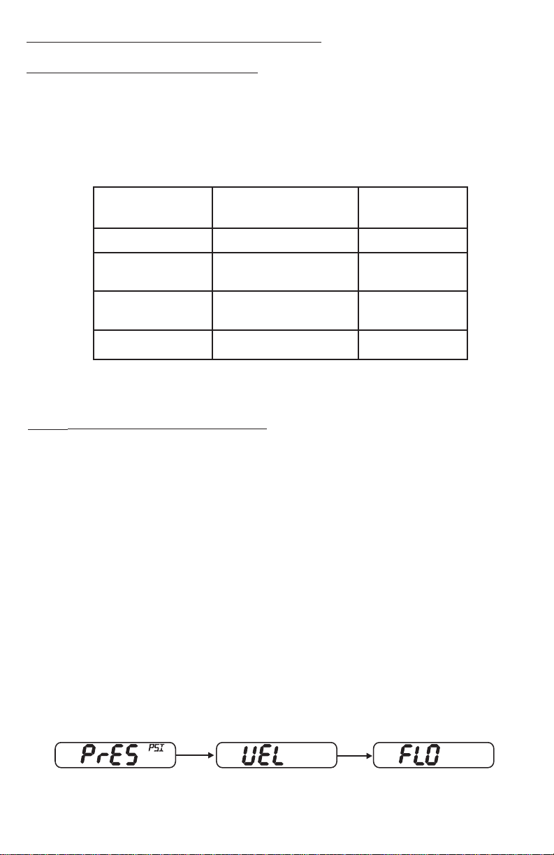
MENU selects the measurement type of the instrument.
PrES
UEL
FLO
If the instrument is set for Velocity, the
SUB MENU. If the instrument is set for Flow, the
KFAC
When scrolling through the
currently set for will show the units in the upper right display. The other measure-
ment types will have a blank upper right display.
- Velocity
- Flow
and
- Pressure
ArEA
SUB MENUS. These will be discussed under Velocity and Flow.
KFAC
ArEA
DIA
OPEr
www.GlobalTestSupply.com
- K Factor
- Area
- Diameter
OPEr
SUB MENUS, the measurement type the unit is
MENU will have an additional
OPEr
11
MENU will have additional
XDIM
- X Dimension
YDIM
- Y Dimension
KFAC
Page 13
PrES
(Pressure) SUB MENU
For pressure measurement, the following units are available:
INWC
- Inches of water column
FTWC
MMWC
CMWC
PSI
INHG
- Feet of water column
- Millimeters of water column
- Centimeters of water column
- Pounds per square inch
- Inches of mercury
MMHG
MBAR
PA
KPA
HPA
OZIN
- Millimeters of mercury
- Millibar
- Pascal
- Kilopascals
- Hectopascals
- Ounce inches
Table 1 Pressure Range vs. Available Units
INWC
FTWC
MMWC
.1000
.2500
.5000
1.000
2.500
.2083
5.000
.4167
10.00
.8333
25.00
2.083
50.00
4.167
100.0
8.333
NOTE:
exceeded above or below full scale by 2%.
OVFL
2.540
6.350
12.70
25.40
63.50
127.0
254.0
635.0
1270
2540
(over flow) or
CMWC
.2540
.6350
1.270
2.540
6.350
12.70
25.40
63.50
127.0
254.0
UnFL
PSI
INHG
MMHG
.1868
.4671
.9342
1.868
.1839
.3678
.1806
.7356
.3613
1.839
.9032
3.678
1.806
7.356
3.613
(under flow) will appear when the ranges have been
4.671
9.342
18.68
46.71
93.42
186.8
MBAR
.2491
.6227
1.245
2.491
6.227
12.45
24.91
62.27
124.5
249.1
PA
24.91
62.27
124.5
249.1
622.7
1245
2491
6227
KPA
.1245
.2491
.6227
1.245
2.491
6.227
12.45
24.91
HPA
.2491
.6227
1.245
2.491
6.227
12.45
24.91
62.27
124.5
249.1
OZIN
.1445
.2890
.5780
1.445
2.890
5.780
14.45
28.90
57.80
UEL
(Velocity) SUB MENU
For velocity measurement, the following units are available:
SFPM
M/S
- Standard feet per minute
- Meters per second
Table 2 Available Velocity Ranges
INPUT RANGE INWC
0 - 0.1
0 - 0.25
0 - 0.5
0 - 1
0 - 2.5
0 - 5
0 - 10
0 - 25
NOTE: Air velocity and flow readings are based upon standard dry air conditions with an
ambient temperature of 70°F and a barometric pressure of 29.92 INHG.
SFPM RANGE
0 - 1266
0 - 2002
0 - 2832
0 - 4004
0 - 6332
0 - 8954
0 - 12.66 x IK
0 - 20.02 x IK
M/S RANGE
0 - 6.431
0 - 10.17
0 - 14.39
0 - 20.35
0 - 32.17
0 - 45.48
0 - 64.33
0 - 101.7
12
www.GlobalTestSupply.com
Page 14

FLO
(Flow) SUB MENU
For flow measurements the following units are available:
SCFM
M^3H
- Standard cubic feet per minute
- Cubic meters per hour
FLO r
(Flow Range) SUB MENU
LO
- 99.99 x 1K flow range
HI
- 999.9 x 1K flow range
Tables 3 -6 show the flow ranges available, and the maximum duct size that can
be set for each input range.
Table 3
FLOr = LO
RANGE
IN WC
0.1
0.25
0.5
1
2.5
5
10
25
Table 5
FLOr = LO
RANGE
IN WC
0.1
0.25
0.5
1
2.5
5
10
25
Maximum Duct Size (English)
SCFM
RANGE
99.99 x 1K
99.99 x 1K
99.99 x 1K
99.99 x 1K
99.99 x 1K
99.99 x 1K
99.99 x 1K
99.99 x 1K
Maximum Duct Size (Metric)
Mˆ3/Hr
RANGE
99.99 x 1K
99.99 x 1K
99.99 x 1K
99.99 x 1K
99.99 x 1K
99.99 x 1K
99.99 x 1K
99.99 x 1K
MAX. DUCT
SIZE, SQ. FT.
78.9
49.9
35.3
24.9
15.7
11.1
7.8
4.9
MAX. DUCT
SIZE Mˆ2
4.32
2.73
1.93
1.37
0.86
0.61
0.43
0.27
Table 4
FLOr = HI
RANGE
IN WC
0.1
0.25
0.5
1
2.5
5
10
25
Table 6
FLOr = HI
RANGE
IN WC
0.1
0.25
0.5
1
2.5
5
10
25
Maximum Duct Size (English)
SCFM
RANGE
999.9 x 1K
999.9 x 1K
999.9 x 1K
999.9 x 1K
999.9 x 1K
999.9 x 1K
999.9 x 1K
999.9 x 1K
Maximum Duct Size (Metric)
Mˆ3/Hr
Range
999.9 x 1K
999.9 x 1K
999.9 x 1K
999.9 x 1K
999.9 x 1K
999.9 x 1K
999.9 x 1K
999.9 x 1K
MAX. DUCT
SIZE, SQ. FT.
789.8
499.5
353.1
249.7
157.9
111.7
78.9
49.9
MAX. DUCT
SIZE, Mˆ2
43.19
27.31
19.3
13.64
8.63
6.10
4.31
2.73
KFAC
KFAC
SUB MENU
K Factor - becomes accessible if the instrument is set for Velocity or Flow.
When the Digihelic
may specify a K Factor. The adjustment range is 0.01 to 2.00. The factory
setting is 1.
®
Controller is used with a pitot tube, the manufacturer
13
www.GlobalTestSupply.com
Page 15

ArEA, DIA, XDIM
These SUB MENUS become accessible if the instrument is set for flow. When measuring flow, the area of the duct must be specified. Tables 3 and 4 show the input
range vs maximum flow and duct size. For a rectangular duct the maximum size is
specified in square feet or meters. For a circular duct the maximum size is specified
as the diameter. X, Y and circular dimensions are entered in feet with 0.01 foot res-
olution for
with 1 millimeter resolution.
FLOr = LO
and
YDIM
SUB MENUS
and 0.1 foot resolution for
FLOr = HI
, or entered in millimeters
ArEA
duct. If a circular duct is selected, the
rectangular duct is selected, the
vated.
DIA
XDIM
YDIM
OUt
The
MENUS are:
CtrL
ISP
AL
- Area, select
CIR
for a circular duct or
XDIM
- Diameter, enter the diameter of a duct
- Enter the “X” dimension of a duct
- Enter the “Y” dimension of a duct
(Output) MAIN MENU
OUt
MENU selects the output type of the instrument. The SUB
- Control type
- SP1 reverse or direct acting
- Alarm type
RECT
DIA
SUB MENU will be activated. If a
and
YDIM
ALrE
AL.H
ALDL
- Alarm reset, manual or auto
- Alarm inhibit
- Alarm delay
for a rectangular
SUB MENUS will be acti-
X
Y
14
www.GlobalTestSupply.com
Page 16

0
100
Process
Reverse Acting
Time
SPH
SPL
Relay Inactive
Relay Active
CtrL
(Control) SUB MENU
1SP
- Single set point
2SP
- Two fully independent set points
SPAL
1SP
(SP1 Reverse or Direct Acting) SUB MENU
DIR
REV
- Single set point and alarm
- Direct. Relay turns on with increasing pressure
- Reverse. Relay turns on with decreasing pressure
100
Process
0
Relay Inactive
Relay Active
Direct Acting
SPH
SPL
Time
15
www.GlobalTestSupply.com
Page 17
The following alarm function SUB MENUS are activated when
SPAL
:
AL
(Alarm Type) SUB MENU
HI
- High alarm
LO
- Low alarm
HILO
- For a high/low guardband type alarm
CtrL
is set to
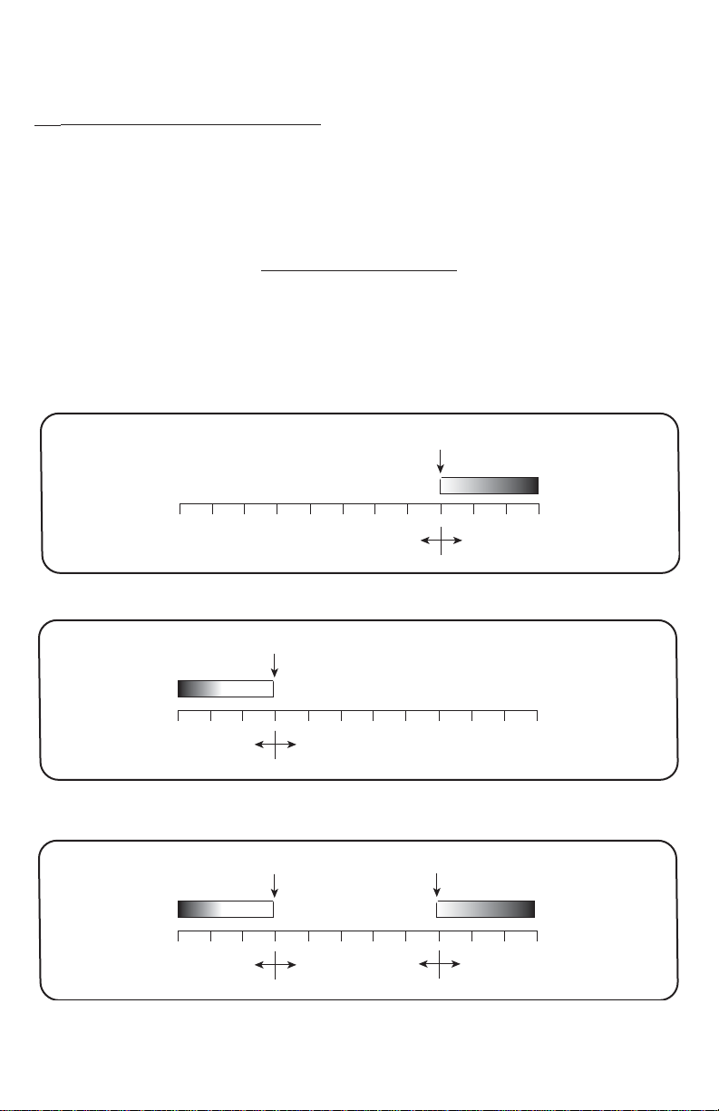
ALARM ADJUSTMENT
Alarm settings are dependent upon the selected alarm mode. The Digihelic
Controller alarm may be configured as a High Alarm, Low Alarm, or High/Low Alarm.
Alarm settings are all absolute and may be set to anywhere within the range of the
instrument. The dead bands of the alarms are fixed at 1% of full scale.
®
HIGH ALARM FUNCTION
MIN. PRESSURE
MIN. PRESSURE
Relay ON Relay OFF
MIN. PRESSURE
ALLO
ALLO
ALHI
Relay OFF Relay ON
LOW ALARM FUNCTION
ALHI
MAX. PRESSURE
MAX. PRESSURE
HIGH/LOW ALARM
FUNCTION
MAX. PRESSURE
Relay ON Relay OFF Relay ON
16
www.GlobalTestSupply.com
Page 18

ALrE
(Alarm Reset) SUB MENU
ONOF
HOLD
AL.H
(Low Alarm Inhibit) SUB MENU
ON
OFF
If
up until the process value passes through the alarm set point once.
ALDL
Sets the amount of time an alarm condition must be continuously met before
the alarm condition is recognized. The alarm delay is adjustable from 0-3600
seconds.
d.S
(Display) MAIN MENU
PEAK
VALy
ZERO
- Automatic reset
- Manual reset. An alarm is reset by the RESET key on the front
panel, or an external reset switch.
- Alarm inhibit is on
- Alarm inhibit is off
AL.H
is selected ON, a low alarm condition is suspended upon power
(Alarm Delay) SUB MENU
- Peak value
- Valley value
- Zero
rESO
Pd.S
DAMP
- Resolution
- Process display
- Dampening level
PEAK
(Peak) SUB MENU
The Peak feature stores the highest pressure reading the instrument has
measured since the last reset or power up. At power up
to the present pressure reading. To manually reset the
press the RESET key while in the
VALy
(Valley) SUB MENU
The valley feature stores the lowest pressure reading the instrument has
measured since the last reset or power up. At power up
the present pressure reading. To manually reset the
RESET key while in the
VALy
www.GlobalTestSupply.com
PEAK
SUB MENU.
SUB MENU.
17
PEAK
VALy
PEAK
VALy
value, press the
is reset
value,
is reset to
Page 19

rESO
(Resolution) SUB MENU
The Digihelic®Controller is capable of displaying four digits of resolution.
However, at very low pressures the instability of the pressure may cause
fluctuations in the least significant digit causing the least significant digit to be
of little value. Three digit resolution (
least one digit to the right of a decimal.
3DIG
- Set display for 3 digit resolution
4DIG
- Set display for 4 digit resolution
Pd.S
(Process Display) SUB MENU
STD
- Display reads pressure, velocity, or flow values
PCT
- Display reads % of full scale value
3DIG
) can only be active when there is at
When the display is reading percent,
the display. The percent display is only available in pressure operation.
DAMP
(Dampening) SUB MENU
Adjust from 1-16
Dampening stabilizes the display from instabilities due to things such as
vibration and excessive pressure fluctuations. The dampening setting adjusts
the amount of readings that are averaged for each display update. Adjust
the dampening value until the display reads a stable value for the application.
AdU
(Advanced) MAIN MENU
POL
- Process output low
POH
- Process output high WR- Modbus®Protocol write enable/disable
MSP1
- Maintenance set point 1
MSP2
POL
- Maintenance set point 2
and
POH
(Process Output Low and High) SUB MENUS
This feature is used in pressure operation only.
Process output low and high are used to scale the 4-20 mA output. Set
POL
to the desired display reading for 4mA output, and set
desired display reading for 20 mA output.
POL
may be adjusted 2% BELOW minimum scale up to
POL
be adjusted from
to 2% ABOVE maximum scale.
ADDR
ZERO
SPAN
PCT
is displayed in the upper right of
- Modbus® Protocol address
- Zero calibration
- Span calibration
POH
POH
must be higher than
POH. POH
to the
POL
may
.
18
www.GlobalTestSupply.com
Page 20

MSP1
SP/ALSP/AL
and
MSP2
(Maintenance Set Point 1 & 2) SUB MENUS
Adjust for the desired maintenance set points when the unit is placed in the
maintenance mode. The deadband is fixed at 2% of full scale. To enter or
leave the maintenance mode, press and hold the for 8 seconds.
ADDR
(Modbus® Protocol Address ) SUB MENU
Modbus®communication instrument address. Set from 1 to 247. This number must match the address number used by the host computer.
To obtain the Digihelic®Controller Modbus®register list please visit
www.dwyer-inst.com
See page 4 for wiring diagram.
WR
(Modbus® Write Protect) SUB MENU
d.S
- Disables write commands from Modbus®. Protocol can only read
information from the instrument.
En
- Enable write commands from Modbus® Protocol. Modbus®can read
information from and write information to the instrument.
ZERO
and
SPAN
(Calibration of Zero and Span) SUB MENUS
The lower display reads
ZERO
Calibration
NOTE: For accurate calibration, DO NOT apply any pressure when
performing this function.
With the display reading
blink. Press ENTER again to complete the zeroing of the instrument or press
MENU
the
SPAN
With the display set to
ENTER key. The upper display will blink. Press ENTER again to complete the
calibration or press the
©Copyright 2009 Dwyer Instruments, Inc.
DWYER INSTRUMENTS, INC.
P.O. BOX 373 • MICHIGAN CITY, IN 46361, U.S.A. Fax: 219/872-9057 e-mail: info@dwyer-inst.com
key to cancel.
Calibration
CAL
in this mode.
ZERO
, press the ENTER key. The upper display will
SPAN
, apply full scale pressure to the unit. Press the
MENU
www.GlobalTestSupply.com
key to cancel.
Modbus®is a registered trademark of Schnieder Automation and Company.
Printed in U.S.A. 7/09
Phone: 219/879-8000 www.dwyer-inst.com
FR# 443246-00 Rev. 4
 Loading...