

Dwyer Instruments DFMT Series, DFMT-10A, DFMT-15A, DFMT-20A, DFMT-25A Installation And Operating Instructions Manual
...Page 1
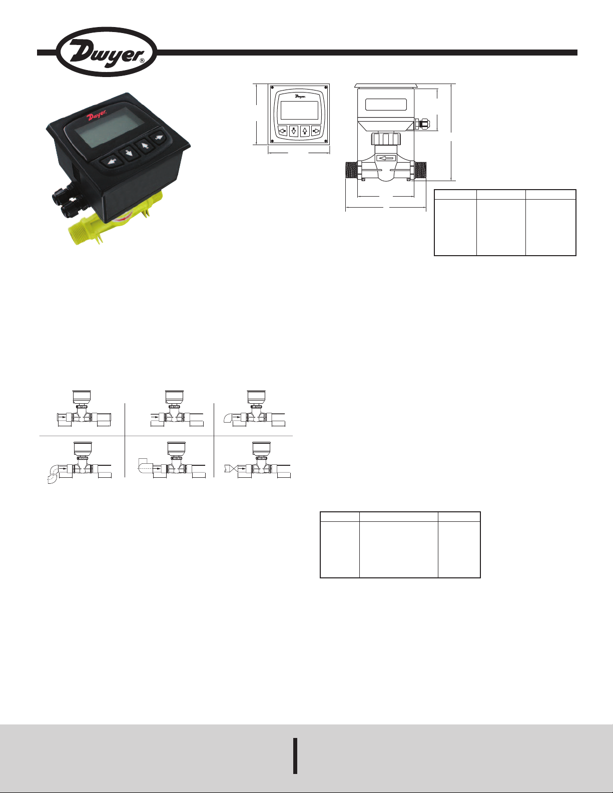
Series DFMT Digital Paddlewheel Flowmeter
3
-7/8˝
[
100]
3-7/8˝
[100]
3
-5/8
[
93]
B
2
-3/4
[
68]
A
15xI. D. 5xI.D . 20xI. D. 5xI.D .
90°elbow
2x90° elbow
division 2
plane
15xI. D. 5xI.D .
20xI. D. 5 xI .D
pump/valve
40xI. D. 5xI.D .25xI. D. 5xI.D .
2x90° elbow
flange
reducing
Specifications - Installation and Operating Instructions
Bulletin F-DFMT
he Series DFMT Digital Paddlewheel Flow Transmitter provides
T
instantaneous, as well as totalizing flow monitoring, making it ideal for commercial
and industrial systems. The large backlit LCD display makes navigating through
the menu structure simple. The Series DFMT uses high accuracy paddlewheel
technology, offers a user selectable 4 to 20 mA or pulse output, and has a corrosion
esistant PVDF sensor giving it long life. Users can reset the totalizer at any time
r
nd set a security password protecting the setting from unauthorized changes.
a
Installation Instructions
The accuracy of these flowmeters can be affected by disturbances such as pumps,
elbows, tees, and valves that are in the flow stream. To reduce the error caused by
these disturbances, pick a section of pipe that is at a distance from any pumps,
bends or valves. The recommended distance away from elbows and pumps is
shown in Figure 1.
Figure 1: Mounting Straight Pipe Runs Required
Mounting Location
To reduce the possibility of causing damage to the Series DFMT, it is
recommended that the meter be mounted in a full flow pipe. Vertical mounting is
acceptable, provided the liquid is flowing up through the meter, or a sufficient back
pressure exists on the downward flow. On horizontal mountings, it is recommended
that the meter be mounted perpendicular to the pipe. For systems that may have
small air pockets at the top of the pipe, the meter can be mounted up to 45° off the
vertical normal.
onnection
C
/8˝
3
/2˝
1
3/4˝
1˝
1-1/2˝
2˝
SPECIFICATIONS
ervice: Compatible clean liquids.
S
ange: See model chart.
R
etted Materials:
W
Sensor and Impeller: PVDF;
Shaft: Ceramic;
O-Rings: Fluoroelastomer.
Accuracy: ±1.5% FS.
epeatability: ±0.5% FS.
R
Output:
Analog: 4 to 20 mA (750 Ω max. loop resistance);
Pulse: NPN square wave output; Frequency: 0 to 2 kHz (adjustable);
Pulse width: 0 to 1000 ms (adjustable).
Electrical Connections: Removable screw terminal.
Temperature Limits:
Process: -4 to 194°F (-20 to 90°C);
Ambient: -4 to 149°F(-20 to 65°C).
Pressure Limit: 145 psi (1.0 MPa).
Power Requirements: 12 to 24 VDC.
Power Consumption: 2 W.
Display: 2.38 x 1.25˝ (60.33 x 31.75 mm) LCD.
Totalizing Display Maximum: 9,999,999,999.
Process Connection: See model chart.
Enclosure Rating: IP65.
Enclosure Material: ABS plastic.
Weight: 1.10 lb (0.5 kg).
Model
DFMT-10A
DFMT-15A
DFMT-20A
DFMT-25A
DFMT-40A
DFMT-50A
Range GPM (m3/h)
0.5 to 8 (0.1 to 2)
0.9 to 18 (0.2 to 4.09)
1.3 to 26 (0.3 to 5.91)
2.2 to 50 (0.5 to 11.36)
6.6 to 105 (1.5 to 23.85)
8.8 to 180 (2 to 40.9)
Connection
3/8˝ NPT
1/2˝ NPT
3/4˝ NPT
1˝ NPT
1-1/2˝ NPT
2˝ NPT
A
˝ 152 mm
6
˝ 152 mm
6
6-1/4˝ 158 mm
6-1/4˝ 158 mm
6-5/8˝ 168 mm
7-1/4˝ 184 mm
B
-3/4˝ 121 mm
4
-1/8˝ 130 mm
5
5-5/8˝ 142 mm
5-1/2˝ 141 mm
6-7/8˝ 175 mm
6-7/8˝ 175 mm
DWYER INSTRUMENTS, INC.
P.O. BOX 373 • MICHIGAN CITY, INDIANA 46360, U.S.A. Fax: 219/872-9057 e-mail: info@dwyermail.com
Phone: 219/879-8000 www.dwyer-inst.com
Page 2
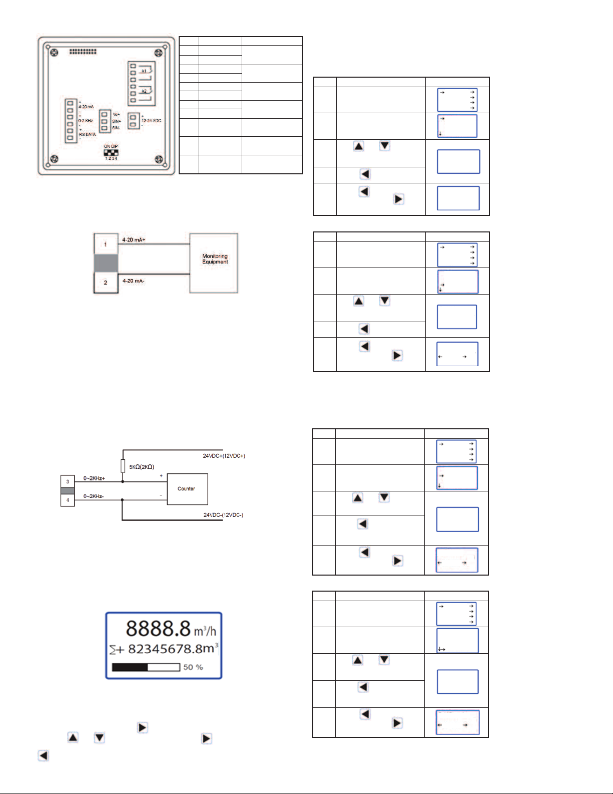
LECTRICAL CONNECTIONS
E
tem
abel
I
L
to 20 mA+
1
4
to 20 mA-
2
4
3
0 to 2 kHz+
4
0 to 2 kHz-
5
RS DATA+
S DATA-
6
1
2
3
4
5
6
7
0
1
8
11
9
1
1
7
8
9
0
1
R
2 to 24 V+
1
2 to 24 V-
1
Vo+
SIN+
IN-
S
unction
F
to 20 Output
4
Frequency/
Pulse Output
RS485
ommunication
C
nput Power
I
erminals
T
Power to
Sensor (Blue)
Communication to
ensor (Red)
S
ommunication to
C
ensor (Black)
S
4 to 20 mA Output
The Series DFMT can provide a variable current output that is proportional to the
detected flow rate. This output can be used in a range of external interface devices,
nd can be calibrated to suit a particular flow range. The maximum load resistance is
a
50 Ω, including the cables used to connect.
7
Pulse (Frequency) Output
The Series DFMT offers a frequency pulsed output that can be configured as a linear
flow proportional frequency output or a standard pulsed output via the unit software.
The maximum pulse output frequency is 5 kHz with a pulse amplitude of 24V and a
aximum load current of 0.2A. The pulse output frequency is adjustable from 100-
m
5000 Hz (please refer to “To Change The Maximum Frequency” under “Pulse Output
Setup”).
When utilizing the unit with a linear proportional frequency output, the liter/pulse
option must be set to 0.0 (please refer to “To Change the Pulse/Liters” under the
“Pulse Output Setup”) and the frequency output signal scaled to the desired range
within the units capability (please refer to “To Set Qmax” under the “System Setup
Menu” to scale frequency output signal).
When utilizing the unit as a standard pulsed output (please refer to “Pulse Output
Setup” under the “System Setup Menu”).
RS485 Communication Output (Optional)
The Series DFMT features optional RS485 Communication. This must be specified at
time of order and will not function otherwise. The RS data communication option will
remain visible in the unit’s software and on the terminal board but will not be
functional. Please contact factory for RS485 communication output capable units.
USING THE SERIES DFMT
When first turned on, the Series DFMT will initialize, and then it will turn to the
measurement reading screen.
The top number is the instantaneous flow reading, followed by the total amount of
liquid passed. The bottom bar shows the percentage of flow in relation to the
maximum flow rate.
To access the menu, press the key on the keypad. Navigate through the menu
using the and to select a sub menu, and the key to enter a sub menu. To
return to the measurement reading screen, or to return from a sub menu, press the
key.
nit Adjustment
U
he Series DFMT can display flow units of L/s, L/min, L/h, m
T
al/s, US gal/min, and US gal/h. The totalization units can be displayed in L, m
g
S gallons.
U
3
/
s, m
3
min, m
/
3
h, US
/
3
and
,
To change flow units:
Steps
Operation Instructions
1
From the menu, select
“Basic”.
elect “PV Units”.
2
S
3
Use and to change
the desired flow units.
ress to select units.
4
P
ress to confirm the
5
P
change, or press to
cancel the change.
o change totalization units:
T
teps
peration Instructions
S
O
rom the menu, select
1
F
Basic”.
“
2
Select “Total Units”.
se and to change
3
U
he desired flow units.
t
4
Press to select units.
5
Press to confirm the
change, or press to
cancel the change.
Display
PV Units
PV Units
isplay
D
Total Units
Total Units
ENT ESC
Basic
System
Calibration
Test
PV Units
PV Decimal
Total Units
Total Decimal
Basic
System
Calibration
Test
PV Units
PV Decimal
Total Units
Total Decimal
m3/h
m3/h
L/h
L/h
L
3
m
L
3
m
Resolution
The Series DFMT has a selectable resolution of up to 3 decimal points for both the
flow and totalization units.
To change flow resolution:
Steps
Operation Instructions
1
From the menu, select
“Basic”.
2
Select “PV Decimal”.
3
Use and to change
the desired flow resolution.
4
Press to select
resolution.
5
Press to confirm the
change, or press to
cancel the change.
Display
PV Decimal
PV Decimal
ENT ESC
Basic
System
Calibration
Test
PV Units
PV Decimal
Total Units
Total Decimal
3
3
3
2
To change totalization resolution:
Steps
Operation Instructions
1
From the menu, select
“Basic”.
2
Select “Total Decimal”.
3
Use and to change
the desired totalization
resolution.
Press to select
4
resolution.
Press to confirm the
5
change, or press to
cancel the change.
Display
Total Decimal
Total Decimal
ENT ESC
Basic
System
Calibration
Test
PV Units
PV Decimal
Total Units
Total Decimal
3
3
3
2
Page 3

amping Factor
D
he Series DFMT has the capability to introduce a damping factor allowing the user
T
o delay the response time of the display and output. This function is used to
t
mooth out a reading of flows that has rapid spikes or dips in the flow rate.
s
To adjust the damping factor:
teps
peration Instructions
S
O
rom the menu, select
1
F
Basic”.
“
2
Select “Damping”.
se , and to
3
U
hange the desired flow
c
esolution.
r
4
Press to select
resolution.
ress to confirm the
5
P
hange, or press to
c
ancel the change.
c
isplay
D
Basic
System
Calibration
Test
PV Decimal
Total Units
Total Decimal
Damping(s)
Damping(s)
Max: 99.9
Min: 0.1
Damping(s)
ENT ESC
02.0
02.0
02.0
03.0
o change low cutoff:
T
teps
peration Instructions
S
O
1
From the menu, select
“System”.
se , , and to
2
U
nput current password.
i
ress to enter password.
P
elect “Signal”.
S
3
Select “Low Cutoff%”
4
se , and to
U
5
nput desired cutoff %.
i
6
Press to select value.
ress to confirm the
7
P
hange, or press to
c
ancel the change.
c
isplay
D
Basic
System
Calibration
Test
Password
New Password
Language
Signal
Pulse Output
Qmax (m3/h)
Low Cutoff%
Low Cutoff%
Max: 9.9
Min: 0.0
Low Cutoff%
ENT ESC
]
*2**
1.0
1.0
1.0
2.0
SYSTEM SETUP MENU
Password Protection
The Series DFMT has a system setup menu that is password protected. The
password must be entered each time a user accesses the system setup menu. The
nit is initially setup to have a password of 0200.
u
o change the password:
T
teps
peration Instructions
S
O
1
From the menu, select
“System”.
2
Use , , and to
input current password.
Press to enter password.
Select “New Password”.
3
Use , , and to
4
create the desired
password.
Press to select the
5
isplay
D
Basic
System
Calibration
Test
Password
New Password
Language
Signal
Pulse Output
New Password
*2**
0200
0200
password.
Press to confirm the
6
change, or press to
cancel the change.
New Password
ENT ESC
0200
0300
PERCENTAGE RANGE
The user can configure the percentage of flow display bar to show a specified range
within the products allowable range. The option “Qmax(m
3
/h)” in the system setup
menu allows the user to set a flow rate at which the bar will show 100%. The option
“Low Cutoff%” allows the user to set a flow rate at which the Series DFMT to display
zero, and set any outputs to zero.
To set Qmax:
Steps
Operation Instructions
1
From the menu, select
“System”.
2
Use , , and to
input current password.
Press to enter password.
3
Select “Signal”.
4
Select “Qmax(m3/h)”
5
Use , and to
create the desired Qmax.
6
Press to select the
desired value.
Display
Password
Qmax (m3/h)
Max: 99999999
Min: 0.000100
Basic
System
Calibration
Test
New Password
Language
Signal
Pulse Output
Qmax (m3/h)
Low Cutoff%
*2**
100.0
120.0
PULSE OUTPUT SETUP
The Series DFMT has a customizable pulse output option. The user can configure
this output’s maximum frequency, the number of liters per pulse, the pulse width,
and whether the pulse level is active low or active high.
o change the maximum frequency:
T
Steps
Operation Instructions
rom the menu, select
1
F
System”.
“
2
Use , , and to
input current password.
Press to enter password.
Select “Pulse Output”.
3
Select “Freq Max(Hz)”.
4
Use , and to
5
input desired frequency
upperlimit.
Press to select value.
6
Press to confirm the
7
change, or press to
cancel the change.
Display
Password
Freq Max(Hz)
Liter/Pulse
PulseWidth(ms)
Pulse Level
Freq Max(Hz)
Max: 5000.0
Min: 100.0
Freq Max(Hz)
ENT ESC
Basic
System
Calibration
Test
New Password
Language
Signal
Pulse Output
4000.0
5000.0
4000.0
5000.0
*2**
To change the liters/pulse:
Steps
Operation Instructions
1
From the menu, select
“System”.
2
Use , , and to
input current password.
Press to enter password.
Select “Pulse Output”.
3
Select “Liter/Pulse”.
4
Use , and to
5
input desired liters per pulse
ratio.
Press to select value.
6
Press to confirm the
7
change, or press to
cancel the change.
Display
Password
Freq Max(Hz)
Liter/Pulse
PulseWidth(ms)
Pulse Level
Liter/Pulse
Max: _____
Min: 0.00055
Liter/Pulse
ENT ESC
Basic
System
Calibration
Test
New Password
Language
Signal
Pulse Output
0.00000
0.01000
4000.0
5000.0
*2**
7
Press to confirm the
change, or press to
cancel the change.
Qmax (m3/h)
ENT ESC
100.0
120.0
Page 4

o change the pulse width:
T
teps
peration Instructions
S
O
rom the menu, select
1
F
“System”.
2
Use , , and to
nput current password.
i
ress to enter password.
P
elect “Pulse Output”.
S
3
Select “PulseWidth(ms)”.
4
se , and to
U
5
nput desired pulse width.
i
6
Press to select value.
7
Press to confirm the
hange, or press to
c
ancel the change.
c
isplay
D
Basic
System
Calibration
Test
Password
New Password
Language
Signal
Pulse Output
Freq Max(Hz)
Liter/Pulse
PulseWidth(ms)
Pulse Level
Pulse Width (ms)
Max: 1000.0
Min: 0.0
Pulse Width (ms)
ENT ESC
*2**
0000.0
0000.0
0000.0
0050.0
o change baud rate:
T
teps
peration Instructions
S
O
rom the menu, select
1
F
System”.
“
2
Use , , and to
input current password.
ress to enter password.
P
elect “RS485 Output”.
S
3
Select “Baudrate”.
4
se , and to
U
5
elect desired baud rate.
s
6
Press to select value.
7
Press to confirm the
change, or press to
ancel the change.
c
isplay
D
Basic
System
Calibration
Test
Password
Signal
ulse Output
P
S485 Output
R
Total Set
RS485 Protocol
Baudrate
Data Bit
Parity
Baudrate
Baudrate
ENT ESC
*2**
9600
19200
9600
4800
PULSE LEVEL
The pulsed output on the Series DFMT can be programmed to be active high or
active low.
o change pulse level:
T
Steps
Operation Instructions
rom the menu, select
1
F
System”.
“
2
Use , , and to
input current password.
Press to enter password.
Select “Pulse Output”.
3
Select “Pulse Level”.
4
Use and to select
5
active high or active low.
Press to select value.
6
Press to confirm the
7
change, or press to
cancel the change.
Display
Password
Freq Max(Hz)
Liter/Pulse
PulseWidth(ms)
Pulse Level
Pulse Level
Pulse Level
Basic
System
Calibration
Test
New Password
Language
Signal
Pulse Output
Active L
Active H
Active L
ENT ESC
Active H
*2**
RS485 COMMUNICATIONS OUTPUT (OPTIONAL)
The Series DFMT also has a RS485 communications output capability. The user
can alter the protocol, baud rate, parity, stop bit, and the device address. The
RS485 output works on 8 data bits.
To set protocol:
Steps
Operation Instructions
1
From the menu, select
“System”.
2
Use , , and to
input current password.
Press to enter password.
3
Select “RS485 Output”.
4
Select “RS485 Protocol”.
5
Use , and to
select MODBUS.
6
Press to select value.
Display
Password
RS485 Protocol
Basic
System
Calibration
Test
Signal
Pulse Output
RS485 Output
Total Set
RS485 Protocol
Baudrate
Data Bit
Parity
MODBUS-RTU
MODBUS-ASC
*2**
To set parity:
teps
peration Instructions
S
O
rom the menu, select
1
F
“System”.
2
Use , , and to
input current password.
ress to enter password.
P
elect “RS485 Output”.
S
3
Select “Parity”.
4
Use , and to
5
select parity type.
Press to select value.
6
Press to confirm the
7
change, or press to
cancel the change.
To set stop bit:
Steps
Operation Instructions
1
From the menu, select
“System”.
2
Use , , and to
input current password.
Press to enter password.
Select “RS485 Output”.
3
Select “Stop Bit”.
4
Use , and to
5
choose the stop bit.
Press to select value.
6
Press to confirm the
7
change, or press to
cancel the change.
isplay
D
Password
Display
Basic
System
Calibration
Test
Signal
ulse Output
P
S485 Output
R
Total Set
RS485 Protocol
Baudrate
Data Bit
Parity
Parity
Parity
ENT ESC
Basic
System
Calibration
Test
Password
Signal
Pulse Output
RS485 Output
Total Set
Data Bit
Parity
Stop Bit
Dev Address
Stop Bit
Stop Bit
ENT ESC
*2**
NONE
EVEN
NONE
EVEN
*2**
1
2
1
2
7
Press to confirm the
change, or press to
cancel the change.
RS485 Protocol
MODBUS-RTU
ENT ESC
MODBUS-ASC
Page 5

o set device address:
T
teps
peration Instructions
S
O
1
From the menu, select
“System”.
se , , and to
2
U
nput current password.
i
ress to enter password.
P
elect “RS485 Output”.
S
3
Select “Dev Address”.
4
se , and to
U
5
nput desired device address.
i
6
Press to select value.
isplay
D
Password
Basic
System
Calibration
Test
Signal
ulse Output
P
S485 Output
R
Total Set
Data Bit
Parity
Stop Bit
Dev Address
Dev Address
o preset totalizer:
T
Steps
Operation Instructions
rom the menu, select
1
F
System”.
“
se , , and to
2
U
*2**
000
101
input current password.
Press to enter password.
Select “Total Set”.
3
elect “Clear Total”.
S
4
Use to select “Yes” or
5
“No”.
ress to select value.
P
6
Display
Basic
System
Calibration
Test
Password
Signal
P
RS485 Output
Total Set
Clear Total
FWD Preset(m3)
FWD Preset(m3)
Max: ______
Min: ______
*2**
ulse Output
000.000000
500.000000
ress to confirm the
7
P
hange, or press to
c
ancel the change.
c
Dev Address
ENT ESC
000
101
Clear and set totalizer
The Series DFMT has a totalizing function that is displayed on the main screen.
This value can be cleared or set to a predetermined value.
o clear totalizer:
T
Steps
Operation Instructions
1
From the menu, select
“System”.
2
Use , , and to
input current password.
Press to enter password.
Select “Total Set”.
3
Select “Clear Total”.
4
Use to select “Yes” or
5
“No”.
Press to select value.
6
Press to confirm the
7
change, or press to
cancel the change.
Display
Basic
System
Calibration
Test
Password
ignal
S
ulse Output
P
R
otal Set
T
Clear Total
FWD Preset(m3)
Clear Total
Clear Total
ENT ESC
*2**
S485 Output
NO
Yes
NO
Yes
7
Press to confirm the
change, or press to
cancel the change.
FWD Preset(m3)
ENT ESC
500.000000
MAINTENANCE/REPAIR
Upon final installation of the Series DFMT, no routine maintenance is required. The
Series DFMT is not field serviceable and should be returned if repair is needed.
Field repair should not be attempted and may void warranty.
ARRANTY/RETURN
W
efer to “Terms and Conditions of Sale” in our catalog and on our website. Contact
R
customer service to receive a Return Goods Authorization number before shipping
the product back for repair. Be sure to include a brief description of the problem
plus any additional application notes.
Page 6

©Copyright 2014 Dwyer Instruments, Inc. Printed in U.S.A. 2/14 FR# R2-444109-00
DWYER INSTRUMENTS, INC.
P.O. BOX 373 • MICHIGAN CITY, INDIANA 46360, U.S.A. Fax: 219/872-9057 e-mail: info@dwyermail.com
Phone: 219/879-8000 www.dwyer-inst.com
 Loading...