

Page 1
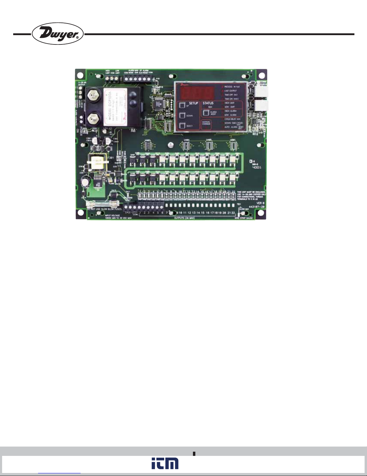
Series DCT1000DC Dust Collector Timer Controller
www. .com
information@itm.com1.800.561.8187
Specifications – Installation and Operating Instructions
Bulletin E-97DC
Thank you for purchasing the Dwyer®DCT1000DC Dust Collector Timer
Controller. You have selected a state of the art dust collector timer control
that will provide years of dependable operation and service.
The Dwyer®DCT1000DC Dust Collector Timer Controller was designed to
be used with pulse-jet type dust collectors for on-demand or continuous
cleaning applications.
Continuous cleaning applications do not require external inputs and can
be used for time based “on-demand” cleaning through use of the cycle
delay feature.
For on-demand applications, the plug-in pressure modules
(DCP100A/200A) can be used to take full advantage of all the features the
DCT1000DC offers, or an external pressure switch can be used for
High/Low limit control.
The Dwyer® DCT1000DC was designed so that it is easy to use, thus
allowing for a quick and easy start up for your dust control applications.
The contents inside this installation and operating manual will guide you
through the features of the DCT1000DC and how they can be applied to
get the most out of your dust control requirements.
SPECIFICATIONS
DCT1000DC Timer Controller:
Output Channels: 6, 10, & 22 channels.
Power Requirements: 10 - 30 VDC.
Solenoid Supply: 3A maximum per channel.
Fuse: 3A @ 250 VAC.
Temperature Limits: -40 to 140°F (-40 to 60°C).
Storage Temperature Limits: -40 to 176°F (-40 to 80°C).
On Time: 10 msec to 600 msec, 10 msec steps.
On Time Accuracy: ± 10 msec.
Off Time: 1 second to 255 seconds, 1 second steps.
Off Time Accuracy: ±1% of the value or ±50 msec, whichever is
greater.
Weight: 1 lb 3.0 oz (538.6 g).
DWYER INSTRUMENTS, INC.
P.O. BOX 373 • MICHIGAN CITY, INDIANA 46361 U.S.A.
Phone: 219/879-8000 www.dwyer-inst.com
Fax: 219/872-9057 e-mail: info@dwyer-inst.com
Page 2

SETUP
www. .com
information@itm.com1.800.561.8187
UP
DOWN
SELECT
STATUS
RUN
ALARM
MANUAL
OVERRIDE
RESET
PROCESS (IN H2O)
LAST OUTPUT
TIME OFF (SEC)
TIME ON (M SEC)
HIGH LIMIT
LOW LIMIT
HIGH ALARM
LOW ALARM
(MIN)
CYCLE DELAY
DOWN TIME CYCLES
(MIN)
AUTO ALARM RESET
(SEC)
6-1/4
[158.75]
6-7/8
[174.62]
2-3/4
[69.85]
8-1/4
[209.55]
8-3/4
[222.25]
Figure 1 – Dimensional Specifications for the DCT1000DC
(shown with optional module DCP100A)
The Dwyer®DCP100A or DCP200A pressure modules are designed
exclusively for use with the DCT1000DC Dust Collector Timer Controller
boards for on-demand cleaning requirements. These series of modules
are available in 10˝ w.c. [2.49 kPa] or 20˝ w.c. [4.98 kPa] ranges, which
allow for differential process pressure measurement as indicated on the
display of the master controller. An isolated 4-20 mA readout channel is
provided for remote pressure display. The 4-20 mA output may be wired
either for use with an external power supply and indicator or using the
isolated on-board 24 volt power supply to power the loop.
1/16
[1.59]
1-13/16
[46.04]
1-11/16
[42.86]
1/2
[12.70]
1
[25.40]
2-7/16
[61.91]
SPECIFICATIONS
Pressure Ranges: 10 in w.c. or 20 in w.c.
Temperature Limits: -40 to 140°F (-40 to 60°C).
Pressure Limit: 10 psi (68.95 kPa).
Pressure Limit (differential): 10 psi (68.95 kPa).
Accuracy: ±1.5% F.S. @ 73°F (22.8°C).
Output Signal: 4-20 mA.
Alarm Contacts: 1.5A inductive load, 3A resistive load @ 30 VAC or 40
VDC.
Process Connections: Two barbed connections for use with 1/8˝ (3.18
mm) or 3/16˝ (4.76 mm) I.D. tubing.
Weight: 5.5 oz (155.9 g).
Page 3
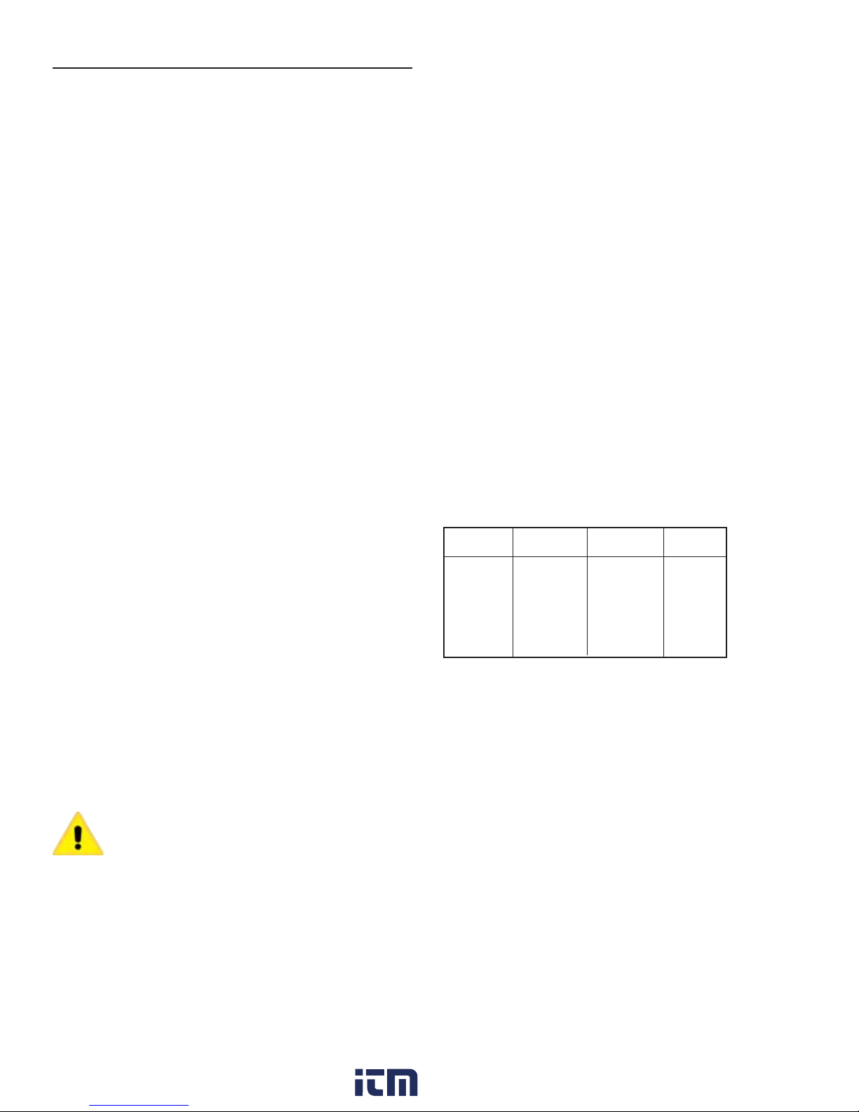
Table of Contents Page No.
www. .com
information@itm.com1.800.561.8187
Figure 1 Dimensional Specifications . . . . . . . . . . . . . . . . . . . .2
1.0 Installing the DCT1000DC . . . . . . . . . . . . . . . . . . . . . . . . . . .3
1.1 Power Requirements . . . . . . . . . . . . . . . . . . . . . . . . . . . . . . . .3
1.2 DCT1000DC Terminal Connections . . . . . . . . . . . . . . . . . . . . .3
1.2.1 External Pressure Connection . . . . . . . . . . . . . . . . . . . . . . . . .3
1.2.2 Manual Override Switch Connection . . . . . . . . . . . . . . . . . . . .4
1.2.3 Down Time Clean Connection . . . . . . . . . . . . . . . . . . . . . . . . .4
1.2.4 Connecting Multiple Timer Boards . . . . . . . . . . . . . . . . . . . . . .4
1.2.5 Continuous Cycle Mode . . . . . . . . . . . . . . . . . . . . . . . . . . . . . .4
Figure 2 Wiring Connections . . . . . . . . . . . . . . . . . . . . . . . . . .4
1.3 DCP Installation . . . . . . . . . . . . . . . . . . . . . . . . . . . . . . . . . . . .5
Figure 3 DCP Installation . . . . . . . . . . . . . . . . . . . . . . . . . . . . .5
1.3.1 Location . . . . . . . . . . . . . . . . . . . . . . . . . . . . . . . . . . . . . . . . . .5
1.3.2 Pressure Model Locking Pins . . . . . . . . . . . . . . . . . . . . . . . . .5
1.3.3 Connecting DCP to Master Controller . . . . . . . . . . . . . . . . . . .5
1.3.4 DCP Connections . . . . . . . . . . . . . . . . . . . . . . . . . . . . . . . . . .5
1.3.5 DCP Maintenance . . . . . . . . . . . . . . . . . . . . . . . . . . . . . . . . . .5
1.4 Alarm Mode Switch Connection . . . . . . . . . . . . . . . . . . . . . . . .5
1.4.1 Alarm Reset Switch Connection . . . . . . . . . . . . . . . . . . . . . . .5
1.4.2 Connecting the 4-20 mA Loop . . . . . . . . . . . . . . . . . . . . . . . . .5
1.4.3 Connecting the Alarm Relay . . . . . . . . . . . . . . . . . . . . . . . . . .6
1.5 Three Position Selection Switch Wiring . . . . . . . . . . . . . . . . . .6
2.0 Programming the DCT1000DC Master
Controller . . . . . . . . . . . . . . . . . . . . . . . . . . . . . . . . . . . . . . . .6
2.1 Last Output Setup . . . . . . . . . . . . . . . . . . . . . . . . . . . . . . . . . .6
2.2 Time Off Setup . . . . . . . . . . . . . . . . . . . . . . . . . . . . . . . . . . . . .6
2.3 Time On Setup . . . . . . . . . . . . . . . . . . . . . . . . . . . . . . . . . . . . .6
2.4 High Limit Setup . . . . . . . . . . . . . . . . . . . . . . . . . . . . . . . . . . .7
2.5 Low Limit Setup . . . . . . . . . . . . . . . . . . . . . . . . . . . . . . . . . . . .7
2.6 High Alarm Setup . . . . . . . . . . . . . . . . . . . . . . . . . . . . . . . . . . .7
2.7 Low Alarm Setup . . . . . . . . . . . . . . . . . . . . . . . . . . . . . . . . . . .7
2.8 Cycle Delay Setup . . . . . . . . . . . . . . . . . . . . . . . . . . . . . . . . . .7
2.9 Down Time Cycles Setup . . . . . . . . . . . . . . . . . . . . . . . . . . . . .7
2.10 Auto Alarm Reset Setup . . . . . . . . . . . . . . . . . . . . . . . . . . . . .7
3.0 Maintenance Support and Diagnostic s . . . . . . . . . . . . . . . .7
3.1 Restoring Factory Defaults . . . . . . . . . . . . . . . . . . . . . . . . . . .7
3.2 Power Indicator . . . . . . . . . . . . . . . . . . . . . . . . . . . . . . . . . . . .7
3.3 Active Channel Indicator . . . . . . . . . . . . . . . . . . . . . . . . . . . . .7
3.4 Comm Check Indicator . . . . . . . . . . . . . . . . . . . . . . . . . . . . . .7
3.5 Error Codes . . . . . . . . . . . . . . . . . . . . . . . . . . . . . . . . . . . . . . .8
4.0 Glossary of Terms . . . . . . . . . . . . . . . . . . . . . . . . . . . . . . . . .8
Customer Service Phone Number . . . . . . . . . . . . . . . . . . . .. . 8
1.0 Installing the DCT1000DC
The open frame design of the DCT1000DC will require an enclosure that
meets appropriate safety and local code requirements. For optimal
performance, the enclosure should also protect the controller from dirt,
water and direct sunlight. There are no special orientation requirements,
and the controller mounts easily using the mounting holes on the factory
installed base plate.
1.2 DCT1000DC Terminal Connections
The line and solenoid connections are located at the lower edge of the
board below the plastic guard. The terminal block is a “Euro” style
connector system that clamps the wire within the connector body. The
connector will accept wire sizes from 14 to 22 AWG. The wire should be
stripped to no more than 0.25 inches to avoid shorts. To assist you in
determining the proper strip length, a strip gauge is provided at the lower
right corner of the board. The connector system used on the DCT1000DC
is specified for single connection but you can piggyback to a single lug
provided that local codes allow for this and good workmanship practices
are followed. To power up the master controller and the channel expander,
connect line power to (+) and (-) (see Dimensional Specifications, Figure
1). Connect the solenoids between the selected output and the solenoid
common. Solenoid common and (+) are internally connected. Switches
connected to the control inputs at the top of the board must be isolated
contacts connected only to the relevant terminal and to the common
terminals. The following subparagraphs describe the external switch
connections. Refer to figure 2 for switch connection illustration.
1.2.1 External Pressure Connection
The controller may be used with an external pressure limit switch or
sensor to provide demand-cleaning operation. The high limit and low limit
inputs may be used for this purpose. A simple on-off system can be
established with a single pressure switch connected to the high limit input.
In this on-demand mode, time on, time off, and cycle delay may be
programmed to define the cleaning cycle. A three pin terminal block (TB3)
provides connection for external high and low limit switches (see Figure 2
on the next page). These switches must be isolated contacts. The
common line must not be connected to equipment ground or protective
ground, since these may introduce electrical noise and cause improper
operation or possible damage to the control board. The operation of these
inputs are summarized as follows (see next page):
Current
Operation
Hold
Hold or Run
Hold
Hold
Run
Hold
Run
Ø Transition from open to closed
≠Transition closed to open
X Either open or closed
Note: If a DCP100A or DCP200A pressure module is installed in the
master controller, the switching functions are ignored.
Low
Limit Switch
Open
X
Ø
Closed
Closed
Closed
≠
High
Limit Switch
Open
Closed
Open
Ø
≠
Ø
Open
Next
Operation
Hold
Run
Hold
Run
Run
Run
Hold
Caution: Do not run control wires, communication cables, or
other class 2 wiring in the same conduit as power leads. The
system may malfunction if class 2 wiring is run together with
power conductors.
1.1 Power Requirements
The DCT1000DC requires 10 to 30 VDC supply power. The solenoids
must be matched to supply voltage. DO NOT exceed 35V, because
transient suppression circuitry will begin to draw high current.
Page 4

4-20 mA CONNECTIONS
www. .com
information@itm.com1.800.561.8187
RECEIVER
USING DCT1000
24V SUPPLY
RECEIVER
OPTIONAL
CONNECTION
SUPPLY
USING EXTERNAL
POWER SUPPLY
SUPPLY
ALARM
LOAD
PRESSURE
LIMIT
SWITCHES
LOW
LIMIT
HIGH
LIMIT
4-20 MA
OUTPUT
4-20 MA
SOURCE
EXTERNAL
INTERNAL ALARM
CONTACTS
NORMALLY OPEN CONTRACTS
MAN
ALARM
D1
LOW
HIGH
LIMIT
COM
LIMIT
TB4
TB5
ALARM
OVR
MODE
CLN
RESET
COM
TB3
COM
TB2
DCT1000DC
MASTER CONTROLLER
OUT
DAISY
CHAIN
IN
DAISY
CHAIN
MASTER CONTROLLER
INPUT MUST NOT BE
CONNECTED
C3Ø4
TB1
L1
INPUT
(INTERNALLY CONNECTED)
SOL
L2
COM
+
-
LINE
12
F1
5
34
SOLENOIDS
(10 CHANNEL SHOWN)
8
6
7
10
9
TB1
Figure 2
Wiring Connections
1.2.2 Manual Override Switch Connection
The manual override function allows the system to be set to the run mode
regardless of other conditions. This mode is enabled when the manual
override terminal and common are connected. It is disabled when they are
disconnected. If the controller is to be run in continuous mode, a jumper
wire may be wired across these terminals. When manual override is
needed on a periodic basis, wire a SPST toggle switch between the
manual override terminal and the common terminal.
1.2.3 Down Time Clean Connection
The down time clean operation forces the system into a run cycle for a
programmed length of time between 0 – 255 minutes. The operation is
initiated by connecting the down time clean terminal to a common
terminal. This function is best accomplished through use of an external
normally open switch.
1.2.4 Connecting Multiple Timer Boards
The DCT1000DC is available with up to 22 channels on single unit. Where
the installation requires more than 22 channels, the system may be
expanded up to 255 channels by daisy chaining multiple controller boards.
The system will automatically detect the total number of channels and
operate as a singel system.
To connect multiple boards together you will need one or more jumper
cables, Model DCA, available from Dwyer Instruments, Inc. in various
lengths. These are connected to the telephone-style connectors at the
upper right side of the controller boards. One board in the system is
designated as the master. Subsequent units become slave boards. The
master controller is the board at the head of the chain having no
connection to its daisy chain connector. Connect the cable from the daisy
chain out connector on connector on the master controller to the daisy
OUT
DAISY
CHAIN
IN
DAISY
CHAIN
TO ADDITIONAL
EXPANDER MODULES
DCT1000DC
SLAVE BOARD
(INTERNALLY CONNECTED)
SOL
L1
L2
COM
+
-
LINE
INPUT
12
5
34
SOLENOIDS
(10 CHANNEL SHOWN)
8
6
7
10
9
chain in connector of the first slave board. Subsequent slave boards are
connected from the daisy chain out connector on one board to the daisy
chain in on the next. The master controller must then be configured to the
system requirements. The display and status indicators of slave boards
are automatically disabled.
Caution: Do not use telephone jumper cables. These have
a “twist” in the connection and may damage the controllers.
Cables designed for use with the DCT1000DC are available
from Dwyer Instruments Inc.
1.2.5 Continuous Cycle Mode
The DCT1000DC has several operating modes available for different
applications. Starting with the most basic mode, it is capable of operating
in a continuous cleaning cycle. This can be initiated by either placing a
jumper between the high limit input and the common, or the manual
override input to the common connection. Controlling this cycle are three
setup parameters: time off, time on, and cycle delay. Time on and time off
specifically deal with the solenoid on time and the time interval between
the end of the on pulse and the start of the next. The cycle delay allows a
delay of up to 255 minutes to be programmed between the end of one
complete cleaning cycle and the beginning of the next. This allows
additional options for defining a cleaning profile.
1.4.3 Connecting the Alarm Relay
With the pressure module installed, a relay contact is provided for
controlling an external alarm. This relay is a single form-A contact. It is
activated when either the high alarm threshold is exceeded, or the
pressure drops below the low alarm threshold. The connection is made at
the two-pin connector TB5. See Figure 2 Wiring Connections
Page 5

1.3 DCP Installation
www. .com
information@itm.com1.800.561.8187
Caution: Prior to installing the DCP100A/200A please
review the operating specifications carefully.
Some operating systems, especially in pneumatic conveying
applications, may see static pressure or vacuum conditions
that exceed the capability of the DCP100A/200A pressure
module.
1.3.1 Location
The system should be located in an enclosure that meets relevant safety
standards and electrical codes. There are no other special orientation
requirements as the pressure module is not orientation sensitive. Care
should be observed when routing the air hoses to ensure that any
potential condensation or moisture will not drain into the sensor. Where
heavy condensation is present, a drip loop or an in-line filter should be
installed to ensure long term operation.
PRESSURE
ALIGNMENT
PINS
MODULE
LOCKING PINS
INSERTED FROM
UNDERNEATH
MODULE ONLY
CIRCUIT
BOARD
INSERT LOCKING PINS UNTIL THEY SNAP FIRMLY IN PLACE
DCP Installation
Figure 3
LOCKING PINS INSERTED
ALL THE WAY INTO THE
CHANNEL
1.3.2 Pressure Module Locking Pins
The DCP100A and DCP200A are supplied with locking pins to secure the
module. In normal operation these are not required since the latching
tabs are sufficient to secure the module even in a high vibration
environment. However if the unit is to be shipped or used where severe
mechanical shock could be encountered the locking pins ensure the
module will not snap out of the board.
To install the locking pins, from underneath the module insert one locking
pin behind each of the two latching tabs. Press these all the way into the
channel. The ends of the tabs will extend through the slots at the top of
these channels. Next insert the module in the board as described above,
making sure it is properly aligned and snaps firmly in place. Press the
exposed locking tabs down until the tab is seated behind the latch in the
board. To remove the module, slide the locking tabs up using a small
screw driver then remove the module as described above. See Figure 3.
1.3.3 Connecting DCP to Master Controller
The pressure module is attached to the Master Controller using integral
connectors on both units. The insertion ports for the pressure module are
located in the upper left quadrant of the DCT1000DC. The pressure
module can be removed by compressing the retaining clips on each end
of the module, then gently pulling the module out of the controller board.
When inserting the module, the following procedure should be adhered to
insure proper installation:
• Examine the bottom of the pressure module and note the orientation of
the connectors.
• Align the module so that these connectors match the connector
receptacles on the controller board.
• Orient the module with the four alignment pins over their respective
mounting holes.
• Gently press the module into the connectors and snap the retaining clips
on either end of the module into their slots.
• Always install and service this device with the power off and a lockout
installed if required. “Hot” plugging the pressure module into an operating
system may damage the system or cause the calibration parameters to
be erased.
When installing or removing the module make sure to orient the module
straight with board. Installing or removing the module at any angle may
break the alignment pins.
Caution: Do not force the module into the connectors. Forcing
the insertion may damage the connectors. Properly aligned,
the module should snap into place.
1.3.4 DCP Connections
When a pressure module is installed, the 4-20 mA process signal and the
alarm relay contacts are available. The 4-20 mA circuit is isolated from
ground and other signals. The alarm relay contacts are isolated, normally
open contacts. Pressure connections may be made to the stepped hose
barbs with either 1/8˝ (3.18 mm) or 3/16˝ (4.76 mm) I.D. tubing.
1.3.5 DCP Maintenance
The pressure module should require very little maintenance under normal
operational conditions. However, periodic calibration may be desirable to
assure accuracy of the readings. The module may be removed and
returned to the factory for calibration.
1.4 Alarm Mode Switch Connection
The auto alarm reset is controlled by the alarm mode switch connection.
To enable the auto alarm reset the alarm mode input must be connected
to a common connection. A jumper may be used when auto alarm reset
is always active. A switch may be used if there are times that the auto
alarm reset must be disabled. The switch must be an isolated contact and
wired such that no connection is made between either of the wires and
ground. See Figure 2 Wiring Connections.
1.4.1 Alarm Reset Switch Connection
The alarm may be reset either by pressing the Alarm Reset button on the
control panel or by an external switch connected between the alarm-reset
terminal and one of the common terminals. The alarm reset will only
operate if the pressure module is installed and the pressure has returned
to a normal condition. See Figure 2 Wiring Connections.
1.4.2 Connecting the 4-20 mA Loop
The pressure module provides an isolated 4-20 mA output, which may be
used to remotely monitor the differential pressure across the dust bags or
cartridges. The connection is made on the master control module at the
terminal block designated for this signal. The connection is a 2-wire
configuration with the option of using either an external 15 to 35 VDC
power source or using the internal 24 VDC source. See Figure 2 Wiring
Connections.
Page 6
4-20 MA
www. .com
information@itm.com1.800.561.8187
OUTPUT
4-20 MA
SOURCE
EXTERNAL
INTERNAL ALARM
CONTACTS
ALARM
MAN
ALARM
HIGH
LOW
COM
LIMIT
LIMIT
TB4
TB5
DT
COM
TB3
MODE
OVR
RESET
CLN
COM
TB2
DCT1000DC
MASTER CONTROLLER
DAISY
DAISY
CHAIN
CHAIN
MODE SELECTION SWITCH
OUT
IN
REAR
SECTION
FRONT
SECTION
CONTINUOUS
OFF
ON DEMAND
TB1
(INTERNALLY CONNECTED)
L2
L1
-
+
(10 CHANNEL SHOWN)
12
34
5
8
6
7
10
9
SOL
COM
OUTPUTS (3A MAX)
(+)
(-)
L1
L2
LINE
INPUT
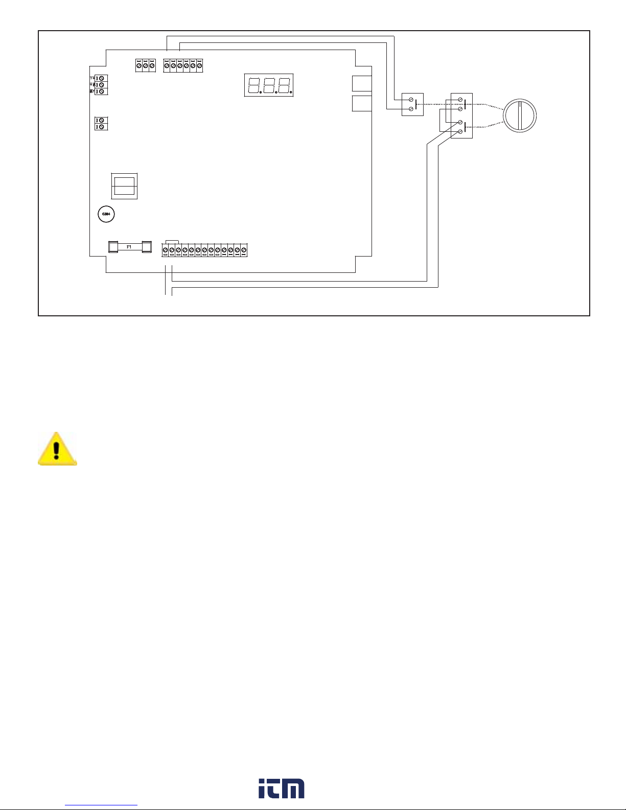
1.5 Three Position Selection Switch Wiring
An optional mode selection switch is available with the weatherproof
enclosure. With this switch the user may select either continuous
cleaning, on-demand cleaning, or off. This switch is supplied factory wired
as shown in Figure 4. The switch has a front and rear section. The front
section, consisting of two independant contacts, controls the power to the
board. These contacts must be wired in parallel as shown in the diagram.
The rear section controls the manual override, which when closed will
force the system into a continuousmuct be reconneccted, follow the wiring
diagram.
Caution: Do not interconnect the low voltage manual override
leads with the power leads. This will destroy the control board
as well as pose a serious shock hazard
2.0 Programming the DCT1000DC Master Controller
We’ve made it easy to navigate the DCT1000DC. Menu items can be
accessed simply by pressing the “SELECT” button. The menu item that
you are currently accessing is indicated by the illumination of an LED. To
change menu items, all you have to do is push “UP” to increase a value
or push “DOWN” to decrease a value. There are no keystrokes that you
need to memorize, special combinations, or passwords that are required.
Three Position Selection Switch Wiring
Figure 4
2.1 • Last Output
The Last Output setup selects the last channel to be activated. When first
selected, the display will flash the last output available in the system. With
single board installations, this will be the number of channels installed,
typically 6, 10 or 22. This value becomes more important when multiple
modules are installed. The last output value flashed will be the sum of all
channels available in the system.
After the last available channel indication has completed, the currently
programmed last channel value is displayed. This value may be changed
using the “UP” and “DOWN” buttons. The minimum value is one while the
maximum value is the maximum number of installed channels, including
all expansion modules.
The default value is the maximum number of channels. Pressing
“SELECT” will change the setup mode to Time Off Setup.
2.2 • Time Off (Sec.)
Time off defines the period of time between solenoid activations when no
channels are enabled. This may be set between one second and 255
seconds. The factory default is 10 seconds. The display will show the
current time off setting when the time off setup mode is entered. The value
may be changed using the Up and Down buttons. Pressing both “UP” and
“DOWN” simultaneously and holding for approximately four seconds will
restore the default value of 10.
The master controller is equipped with an on board display and
programming information center. The controller will power-up with the
process indicator illuminated. If a pressure module is installed, the display
will indicate the measured pressure in inches of water (w.c.); otherwise it
will normally be blank.
2.3 • Time On (msec)
Time On Setup sets the solenoid on time. The display will indicate the
currently programmed time on setting. This is measured in milliseconds.
Using the “UP” and “DOWN” buttons, the value may be changed. The
value may be set between 10 msec and 600 msec in 10 msec increments.
Pressing the “UP” and “DOWN” buttons simultaneously for approximately
four seconds will restore the factory default value of 100 msec. Pressing
the “SELECT’ button will advance the setup mode to the High Limit setup
if the pressure module is installed. With no pressure module, it will step to
Cycle Delay Setup.
2.4 • High Limit [Only available when DCP connected]
The High Limit Setup, available only with a pressure module installed,
sets the pressure at which the cleaning cycle will begin. This value may
be between zero and the pressure module full scale pressure. Normally,
the High Limit should be above the Low Limit. If, however, the High Limit
pressure is set below the Low Limit, the cleaning cycle will begin when the
High Limit is exceeded and stop when the pressure falls below the High
Limit. The Low Limit in this case will have no effect. Pressing “SELECT”
will change the system to the Low Limit Setup mode.
Page 7

2.5 • Low Limit [Only available when DCP installed]
www. .com
information@itm.com1.800.561.8187
The operation of the Low Limit, available only with a pressure module
installed, is identical to the High Limit except this value sets the pressure
where the cleaning cycle will end. The upper settable value is the
calibration pressure of the pressure module and the lower limit is zero.
Pressing “SELECT” will change the system to the High Alarm Setup
mode.
2.6 • High Alarm [Only available when DCP installed]
The operation of the High Alarm Setup is identical to the High and Low
Limit Setup and is only available when a pressure module is installed. The
High Alarm default is 0. The upper settable value is the full scale pressure
of the pressure module and the lower limit is zero. Pressing “SELECT” will
change the system to the Low Alarm Setup mode.
2.7 • Low Alarm [Only available when DCP installed]
The operation of the Low Alarm Setup is identical to the High and Low
Limit Setup. The Low Alarm default is 0. The upper settable value is the
full scale pressure of the pressure module and the lower limit is zero.
Pressing “SELECT” will change the system to the Cycle Delay Setup
mode.
2.8 • Cycle Delay (min)
The cycle delay inserts a delay time between the end of the last channel
and the beginning of the first channel. This may be set to between zero
and 255 minutes. The factory default is zero. Setting the value to zero will
disable the delay. Pressing “SELECT” will change the system to the Down
Time Cycles Setup mode.
2.9 • Down Time Cycles (min)
The Down Time Cycles setup will select a value between zero and 255
minutes. The factory default is one minute. Selecting zero will disable the
operation. When the down time cycles is activated by shorting the down
time cycles input to the common terminal, (see figure 2) the system will
enter a forced cleaning mode for the programmed duration. Note: The
cycle delay, if one is programmed, will not be inserted in the timing cycle.
Pressing “SELECT” will change the system to the Auto Alarm Reset Setup
mode, if a pressure module is installed, or to Process when no pressure
module is available.
2.10 • Auto Alarm Reset (sec) [Only available when DCP installed]
The Auto Alarm Reset Setup, available only when a pressure module is
installed, allows the auto alarm reset time to be selected. This value may
be set between zero and 255 seconds. The factory default value is five
seconds. When the auto alarm reset is enabled by shorting the auto alarm
reset terminal to a common terminal, (See Figure 1) the alarm will be reset
after the pressure returns to the normal range and the timeout has
expired. Pressing “SELECT” will change the system to Process mode.
3.0 Maintenance Support and Diagnostics
We have also included a number of features that will aid maintenance
personnel in diagnosing problems or verifying that the system is operating.
3.1 Restoring Factory Defaults
The DCT1000DC has been programmed with factory default values that
meet most industry operating conditions. In the event that you want to
restore all of the parameters to the original factory default values:
(1) Return the master controller to the process mode.
(2) Press and hold both “UP” and “DOWN” buttons.
The display will indicate a 10-second countdown, at the end of which all
parameters will be restored to factory defaults. Releasing the switches
prior to the end of the count will stop the process and no modification will
be made. Likewise, in each of the parameter setup modes, pressing and
holding the “UP” and “DOWN” buttons simultaneously will reset the
individual default value, leaving other settings unchanged.
3.2 Power Indicator
A power on LED indicator is provided at the center left edge of the board.
This will be illuminated when the power supply is operating properly. If the
power LED is not illuminated, the primary power may be off or there is a
fault in the power circuit.
3.3 Active Channel Indicator
Located just above the solenoid terminations, you will find that each
channel is provided with an LED that is illuminated when the triac switch
is on. This allows a visual correlation between the channel being pulsed
and the operation of the solenoid.
3.4 Comm Check Indicator
The comm check indicator can be found in the upper right hand corner of
the slave and master controller board (just above the “out” terminal, a
telephone style connector). This indicator is used for two purposes. First,
on a master controller a brief flash once per second is produced to
indicate that the system is operating. Second, this indicator is used to
show when the communication check operation is performed on slave
boards. The master controller will check each of the slave boards at a rate
of about one inquiry per second, starting with the slave board connected
directly to the master controller and ending with the last slave board in the
chain. The master controller will flash its Comm Check LED for about 250
msec each time it makes a communication check. The external module
selected for test will also flash its Comm Check LED for about the same
time each time it is interrogated. Observing this test sequence will indicate
that the communication between boards is operational. When a slave
board powers up, the Comm Check LED will be illuminated continuously.
It will be extinguished when the master controller has initialized its
communication channel. This indicator then shows that a master
controller is operating and that each slave board is responding properly on
the daisy chain.
Page 8
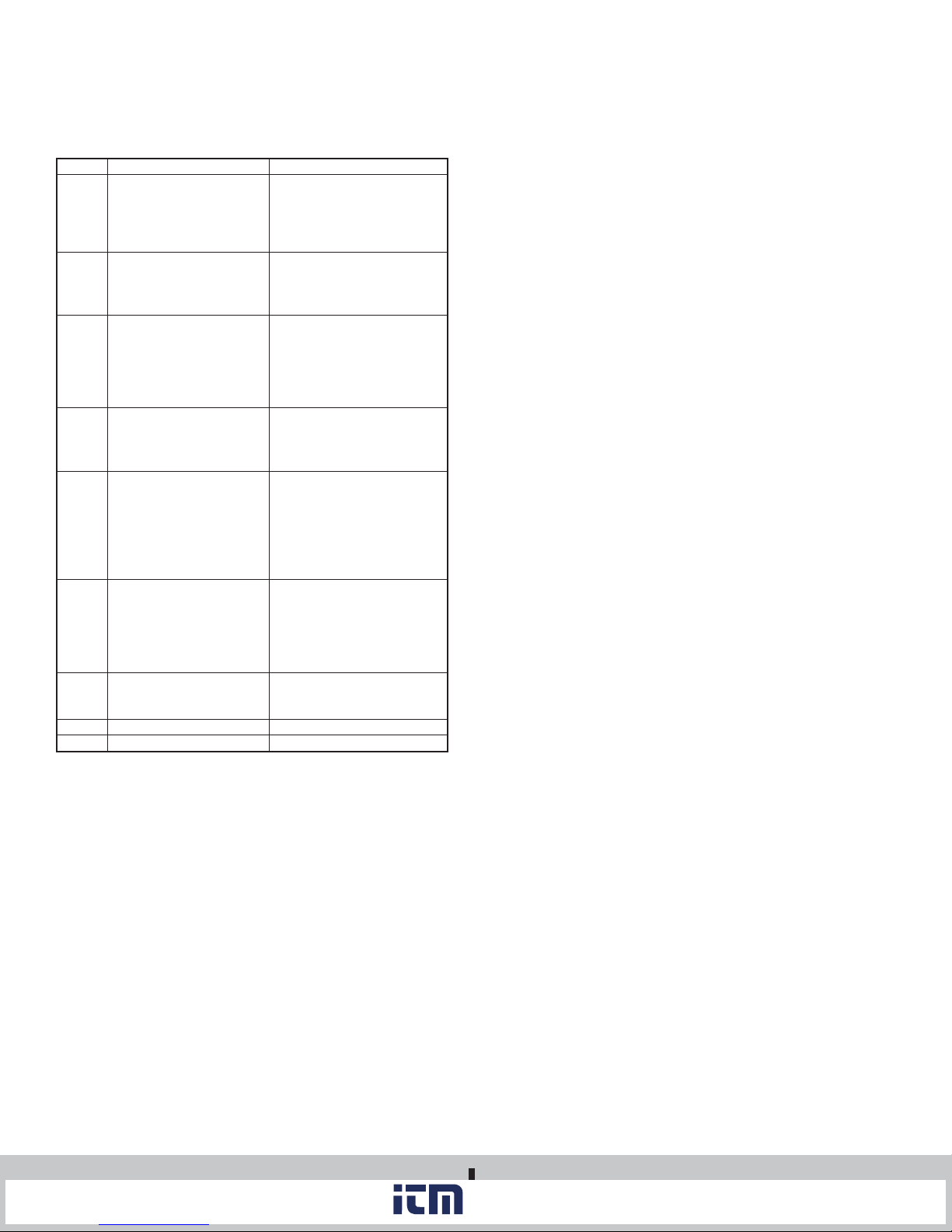
3.5 Error Codes
www. .com
information@itm.com1.800.561.8187
Error codes will be displayed on the three-digit display when certain faults
occur. Most of these indicators are associated with the daisy chain
communication, but certain error codes pertain to single board operation
also. These codes are:
Display
Err 1
Err 2
Err 3
Err 4
Err 5
Err 6
Err 7
Err 8
Err 9
Meaning
This is a “watchdog” reset
that is enabled when the
master controller isn’t able
to cycle through its
operation.
The pressure module has
failed to respond to the
request of the master
controller.
Communication error in the
daisy chain interface. This
will only appear when the
master controller is used in
conjunction with a slave
board.
The master controller has
detected a change in
module configuration or a
fault in one of the modules.
If the fault described in “Err
4” is not corrected, the
master controller will
reconfigure the modules
that are responding
properly and operate at a
degraded condition.
A message error affecting
the software of the master
controller or one of its
modules.
Indicates that one of the
triac drivers are not
functioning.
Internal Error.
Unassigned message code.
Action Required
Make sure all electrical
connections are appropriately
shielded so the master
controller is not disrupted by
noise.
The master controller will try
to recover from the fault. If
unsuccessful, replace the
pressure module.
Make sure the control cable
used in the daisy chain
interface is properly shielded
from noise.
Reinstall all modules in
accordance with the
instructions in the factory IOM.
Reinstall all modules. Contact
factory if the problem persists.
Check the integrity of all
connecting cables used to
drive slave boards for
additional solenoids. Also
check the electrical grounding
of the system installation.
Return to factory for
evaluation and repair.
Contact the factory.
Contact the factory.
4.0 Glossary of Terms
• Run Mode: The term used when the timer board is firing the
solenoids.
• Pressure Module: The pressure measurement subsystem that
includes the software and hardware for on-demand cleaning, alarms
and signal retransmission of the process variable (i.e., the differential
pressure across the dust bags).
• Master Controller: The primary timer board that contains all of the
major features, connections for external inputs and power to drive the
DCT1000DC Dust Collector Timer Controller system.
• Power DC Guard: A plastic shield that covers the output triacs and
other line voltage circuitry.
• Demand Cycle Mode: A process in which the run mode is enabled
through the on-board pressure module or an external switch.
• Euro Connector: A “caged” connection used to terminate solenoids,
incoming power, or external switches on the DCT1000DC.
• Continuous Cycle Mode: A time based cycling mode dependent on
solenoid time on/off settings and time set between complete cycles.
• Manual Override: Allows the user to override the DCT1000DC
remotely or from the master controller panel through use of a switch or
a wire jumper.
• Slave Board: A channel expander that is used in conjunction with the
master controller to accommodate additional solenoids on larger dust
collection systems. It can be recognized easily as it does not have the
on-board display panel or the power supply present. A master
controller may also be used as a slave board.
Still need help? Please feel free to contact one of our customer service representatives or visit us on the web at www.dwyer-inst.com. Thank
you for choosing Dwyer Instruments, Inc.
©Copyright 2010 Dwyer Instruments, Inc.
DWYER INSTRUMENTS, INC.
P.O. BOX 373 • MICHIGAN CITY, INDIANA 46361 U.S.A.
Printed U.S.A. 10/10
Phone: 219/879-8000 www.dwyer-inst.com
Fax: 219/872-9057 e-mail: info@dwyer-inst.com
FR# 443123-05 Rev. 3
 Loading...