

Page 1
Bulletin IN-523
1/4 N.P.T.
6
-1/64
[
152.8]
D
IA.
7/8 [22.23]
A
DJUSTMENT SCREWS
2-1/4
[57.15]
1
-5/8
[
41.2 8]
1
/2 [12.7]
C
ONDUIT HOLE
5/8 [15.88]
MERCOID
C
ONTROL
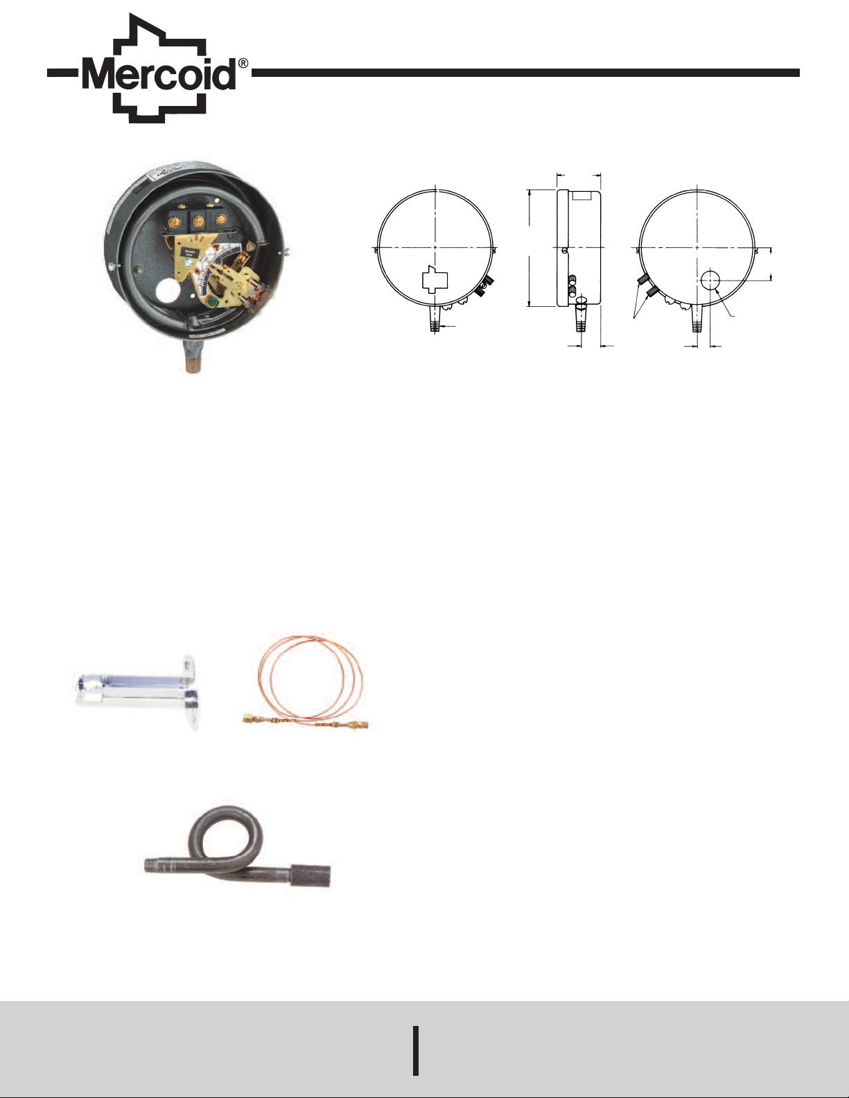
Series DA/DS-7000 Bourdon Tube Pressure Switches
Specifications - Installation and Operating Instructions
eries DA/DS-7000 Bourdon Tube Pressure Switches are SPDT snap-action
S
witches that combine extremely high sensitivity and repeatability with easily
s
adjustable set and reset points through non-interactive external adjustments.
These switches have visible calibrated dials for set points and on-off indicators to
indicate switch actuation. DA models are equipped with two external adjustments.
One sets the high pressure operating point; the other sets the reset point.
Deadband or the difference between set and reset points is adjustable over the full
scale. DS models have a fixed deadband.
Note: The DS7300 has no status indicator.
INSTALLATION
The switch may be mounted in any position. Select a location recommended by
equipment manufacturer. Where excessive vibration occurs, mount the switch
remotely, using an appropriate remote connection and mounting bracket. See
accessories, below.
ACCESSORIES
Mounting Bracket
33-25
Remote Connection
49-62: 6 ft copper - 300 psig max
49-62HP: 6 ft copper - 2500 psig max
49-210: 12 ft 316 SS - 3000 psig
SPECIFICATIONS
Wetted Materials: Brass, 403 SS, or 316 SS.
Temperature Limit: 180°F (82°C).
Pressure Limit: Maximum pressure of the operating range.
nclosure Rating: General purpose, weatherproof or explosion-proof.
E
epeatability: ±1% of full operating range.
R
Switch Type: See circuit chart.
Electrical Rating: See electrical ratings chart.
Electrical Connections: Screw terminal.
Conduit Connection:
General purpose: 1/2˝ hole for conduit hub;
Weatherproof: 1/2˝ conduit hub;
Explosion-proof: 3/4˝ female NPT.
Process Connection:
General purpose and weatherproof: 1/4˝ male NPT, 1/2˝ male NPT on ranges
15S and 16S;
Explosion-proof: 1/2˝ male NPT and 1/4˝ female NPT.
Mounting Orientation: Vertical.
Set Point Adjustment: Thumbscrew.
Weight:
General purpose: 4 lb (1.8 kg);
Weatherproof: 6 lb (2.7kg);
Explosion-proof: 8 lb (3.5 kg).
Deadband: See Ranges and Differentials Chart.
CAUTIONS:
Control movement must not be oiled. Do not overload. Note electrical rating on
name plate and be sure that total current passing through the switch is within specified rating.
When testing a boiler or system, never exceed maximum pressure rating on control or it may be seriously damaged. Remove control if higher pressures are
required.
Do not fail to use a siphon on steam where range is 35 lbs (2413 mbar) or more.
Pigtail Siphon
42-52: 250 psig max
42-58: 2000 psig max
MERCOID DIVISION
DWYER INSTRUMENTS, INC. Fax: 219/872-9057 e-mail: info@dwyer-inst.com
P.O. BOX 258 • MICHIGAN CITY, INDIANA 46360, U.S.A.
Phone: 219/879-8000 www.dwyer-inst.com
Page 2
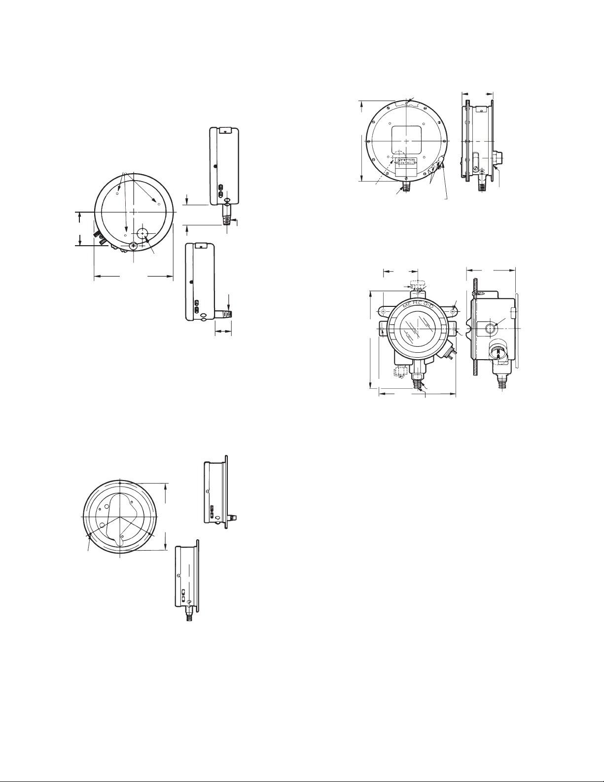
GENERAL PURPOSE CONTROLS, TYPES DA, DL, DR, DS
M
OUNTING
HOLES (OPTIONAL)
1/29 NPT
9-7/89
BREATHER
(OPTIONAL)
59
3
/49 CONDUIT
CONNECTION
13/329 DIA.
1/49 NPT
7-3/49
3-1/29
6-1/29 DIA.
13/649
DIA.
BACK
CONNECTION
BOTTOM CONNECTION
DA24
DA34
DA44
DA23
DA33
DA43
HOLES FOR
F
LANGE SCREWS
1/29 CONDUIT
CONNECTION
6-1/649 DIA.
1/49 NPT
1-1/29
1/49
NPT
1
-1 /8 9
[«\«1
DA21
DA31
DA41
DA22
DA32
DA42
3
REAR FLANGE MOUNTING HOLES (3)
2-13/169
1/49 NPT
[
\««1
79 DIA.
ADJUSTMENTS
1
/29
CONDUIT
HUB
G
ASKETED COVER
Mount control in any position. Do not twist the case when installing. Use a wrench
on the square part of the control connection. On controls with operating Range No.
5S (500 to 5000 psi (34.47 to 344.75 bar)) or Range No. 16S (800 to 8000 psi
1
55.16 to 551.6 bar)), be sure the special sealing nut (with PTFE insert) is turned
(
o the uppermost threaded section of the 1/2″ pressure connection. Apply a flat
t
pen-end wrench to the flat side of the bottom pressure connection when piping the
o
control. After properly connecting the control, tighten the sealing nut to assure a
leak-proof connection.
WATERTIGHT AND WEATHERPROOF
NEMA 2, 3, 4, 5, TYPES DAW, DRW, DSW
hese switches are supplied with flanged case, bottom connection, for surface
T
ounting only.
m
Weather-Proof Types DAW, DSW, DRW
EXPLOSION-PROOF TYPES DAH, DRH, DSH
ount with mounting lugs attached to control housing.
M
FLANGED CASE CONTROLS
Mount by means of the three holes in the flange. Note: Series D7030 when used
for steam with operating ranges of 35 psi (2.413 bar) or higher, must be siphoned
to prevent live steam entering the Bourdon tube. With high-pressure steam
exceeding 100 psi (6.895 bar), use a remote connection. (Note accessories on
Page 1.)
Series D-7020 incorporate an orifice as standard in the pressure connection to
dampen surges or pulsations.
General Purpose Types DA, DS, DR, DL
Flange for Surface Mounting
Explosion-Proof Types DAH, DRH, DSH
WIRING
Wire in accordance with the National Electrical Code and local regulations. For
general purpose controls, use a short piece of BX between the rigid conduit and the
control so the control will not be subjected to conduit expansion and contraction.
Where the control is directly connected into the load circuit, it should be connected
into the hot side of the line. Do not exceed electrical rating as stamped on the control nameplate. DS-7300 controls are equipped with a terminal block. Field connection should be made to terminal block pole in common with required pole of the
control’s switch. The color code is:
Black - Common
Blue - ON Hi
Red - ON Lo
Page 3

ADJUSTMENTS: HOW TO SET OPERATING POINT
PIVOT POINT
BEARINGS,
TOP & BOTTOM,
BUSHED WITH ACETAL
SWITCH CARRIER
STOP POST SLEEVED
WITH ACETAL
ACETAL PIN
ACETAL PIN
BAR LINK
ACETAL BRUSHED
PIVOTAL END
BEARING &
CONNECTION
BAR PIN OF
ACETAL
ouble Adjustment Types - Fully Automatic:
D
ith double-adjustment switches (prefixed DA, DAH or DAW), adjust the upper
W
ointer ˝U˝ to set HIGH PRESSURE POINT for switch operation and adjust the
p
ower pointer ˝L˝ to set LOW PRESSURE OPERATING POINT. The difference
l
between the ˝U˝ and ˝L˝ pointers is the operating differential between ˝on-off˝
switch operation.
witch Indicator
S
range indicates
O
n high
o
U - Upper Pointer
- Lower Pointer
L
Double-Adjustment Types Fully Automatic
Semi-Automatic Control with Manual Reset:
Models prefixed DR, DRH, DRW and with suffix L or U (example: DR-7021-153U)
ave a single adjustment that sets the operating point for automatic operation. A
h
ush-button reset must be operated manually to restore the circuit to the original
p
position after automatic operation. Example: Type DR-7021-153L has a circuit that
opens automatically on a pressure rise to the pressure indicated by the pointer on
the scale; no matter how much the pressure drops, the circuit will not re-close until
the reset button is operated. Suffix L denotes control will operate automatically on
an increase. Suffix U denotes control will operate automatically on an decrease.
SINGLE ADJUSTMENT TYPES—FULLY AUTOMATIC:
odels prefixed DS, DSH, DSW, N3DSW are equipped with a single adjustment.
M
ifferential is fixed (not adjustable). The single pointer on the scale sets the pres-
D
ure at which switch operation occurs. Differential is listed in chart indicates
s
pproximate fixed differential.
a
witch Operating
S
ndicator
I
Single Adjustment
ingle Adjustment Types Fully Automatic
S
LOCKING DEVICE
When the control has been adjusted to desired range, the locking bar may be
nserted between the adjustment screws with the slot passing over the projecting
i
lugs. By placing a sealing wire between the locking bar and the hole in the lug protruding from the adjustment assembly, adjustments cannot be tampered with.
For DRF, DAW, DRW, adjusting knob cover may be sealed in place with sealing
ire through cover bolt hole. For DAH, sealing wire may pass through locking bar
w
nd hole in hub above adjusting knobs.
a
ACETAL BUSHED MOVEMENT ˝B˝
Acetal bushed movements prolong control life by alleviating wear of metal surfaces
due to excessive vibration and/or pulsation. They also prolong switch life in environments where corrosion may be a factor. Models with Acetal movements are
identified by the letter ˝B after the suffix number. Examples: -153B, -153UB, etc.
Semi-Automatic Types with Manual Reset
Adjustment
Reset
CONTROL NUMBER
Part of the control number (the fourth number in the sequence) identifies the type
of control case. Digit 1 of 7021, 7031, 7041, denotes a plain case with bottom connection. Digit 2 of 7022, 7032, etc., denotes a plain case with back connection.
Digit 3 of 7023, 7033, 7043, etc., denotes a flanged case with bottom connection.
Digit 4 of 7024, 7034, etc., denotes a flanged case with back connection. (Digit 3
of 7321, 7331, 7341, etc., denotes hermetically sealed snap switch.)
Acetal Bushed Movement ˝B˝
CIRCUITS (SWITCH OPERATION)
Suffix number after control number denotes switch action:
Suffix -153 designates SPDT; one circuit closes as other circuit opens.
Suffix - 804 designates two SPDT switches; two close, two open.
Page 4

ourdon Tube
B
aterial
M
rass
B
Bourdon Tube
03SS
4
Bourdon Tube
316SS
Bourdon Tube
316SS
Bourdon Tube
Carbon Steel
Bottom
Connection
Code
D
E
F
G
K
ANGES:
R
ange
R
Number
2
3
1
A
3
4
7
2
5
6
7
8
9
Range
umber
N
25S
26S
S
5
6S
S
8
9S
AS
9
10S
11S
12S
3S
1
15S
6S
1
Range
Number
26E
23E
6E
24E
9E
21E
22E
11E
13E
Range
Number
23K
24K
9K
Electrical Ratings
120V
10A
15A
12A
djustable
A
Operating Range
psig)
(
0-30˝ Hg Vac
.0˝ Hg Vac-12
1
1/8-15
/8-20
1
-35
1
25˝ Hg Vac-50
-60
2
5-100
-150
5
10-200
0-300
1
Adjustable
perating Range
O
(psig)
0˝ Hg Vac-60
3
30˝ Hg Vac-75
2-60
-100
5
10-200
0-300
1
40-350
5-600
2
50-1000
00-1500
1
300-2500
00-5000
5
800-8000
Adjustable
Operating Range
(psig)
30˝ Hg Vac- 75
5-75
10-100
10-150
10-300
30-400
75-800
100-100
200-2500
Adjustable
Operating Range
(psig)
5-75
10-150
10-300
AC Capacity
240V
10A
15A
10A
5A @ 250 AC. Resistive & Inductive; 30V DC Resistive
YPE DA Double
T
Adjustment Minimum
ifferential (psig)
D
SPDT
A-7031-153
D
AW-7033-153
D
DAH-7031-153
3.5˝ Hg
1
6
6
6
7
2
1
9
3.5
1
24
4
2
37.5
PDT
S
A-7021-153
D
DAW-7023-153
AH-7021-153
D
18
2.5
2
13.5
19.5
2.5
2
28.5
0
3
67.5
142.5
195
90
3
1350
250
2
SPDT
A-7041-153
D
DAW-7043-153
DAH-7041-153
15
12
15
16.5
42
78
180
285
600
SPDT
DA-7041-153
DAW-7043-153
DAH-7041-153
12
16.5
42
See Code F*
See Code D
Electrical Ratings
480V
NA
15A
5A
5A @ 125/250 AC, Resistive; 30V DC Resistive
S
DS-7231-153
D
DSH-7231-153
3
1
1.5
1
1.5
2
2
2
3
4.75
6
SPDT
D
DSW-7223-153
DSH-7221-153
3
3.5
3
3.5
4
7
7
1
22
3
60
2
500
SPDT
D
DSW-7243-153
DSH-7241-153
3.5
4
3.5
4.5
8
12
25
35
75
SPDT
DS-7241-153
DSW-7243-153
DSH-7241-153
4
4
8
See Code E
DC Capacity
120V
.5A
NA
.5A
PDT
SW-7233-153
˝ Hg
.5
.5
.5
.5
.5
S-7221-153
.5
.75
2
5
00
S-7241-153
ingle Adjustment
S
ixed Differential (psig)
F
2) SPDT
(
D
DSW-7233-804
D
2.5˝ Hg
1
1.25
1
1
2
1
2
3
4
6
2) SPDT
(
D
D
DSH-7221-804
3
3
2.5
3
4
6
6
1
20
3
50
1
180
2) SPDT
(
DS-7241-804
DSW-7243-804
DSH-7241-804
4
2.5
4
3
6
10
17
30
95
(2) SPDT
DS-7241-804
DSW-7243-804
DSH-7241-804
2.5
3
6
See Code D
240V
.25A
NA
.25A
TYPE DS
S-7231-804
SH-7231-804
.25˝
.25
.5
.5
.5
S-7221-804
SW-7223-804
0
0
10
AC Horsepower
120V
1/8
1/4
1/4
SPDT
S-7331-153
D
DSW-7333-153
SH-7331-153
D
5˝ Hg
˝
3
3
3
3
3.75
3
3.75
.25
5
.75
6
9
PDT
S
DS-7321-153
SW-7323-153
D
DSH-7321-153
5.25
.25
5
4.5
.25
5
7.125
0.5
1
10.5
18
33
2.5
5
90
00
3
750
SPDT
S-7341-153
D
DSW-7343-153
DSH-7341-153
5.25
6
5.25
6.75
12
18
37.5
52.5
112.5
SPDT
DS-7341-153
DSW-7343-153
DSH-7341-153
6
6
12
See Code K
240V
1/4
1/2
1/2
Circuit
Suffix No.
-153
-804
*Note: Minimum differentials increase when using multiple circuits. Controls using #804 circuits in ranges
over 35 psig have 30% higher minimum differentials; ranges under 35 psig are not available in Code F.
©Copyright 2013 Dwyer Instruments, Inc. Printed in U.S.A. 1/13 FR# 76-441853-00 Rev. 3
Switch Action on Pressure Increase
SPDT: one OPENS as one CLOSES
(2) SPDT: two OPEN as two CLOSE
MERCOID DIVISION
Electrical Rating Code
D-7000 D-7200 D-7300
D E K
F* G
Phone: 219/879-8000 www.dwyer-inst.com
DWYER INSTRUMENTS, INC. Fax: 219/872-9057 e-mail: info@dwyer-inst.com
P.O. BOX 258 • MICHIGAN CITY, INDIANA 46360, U.S.A.
 Loading...