

Page 1
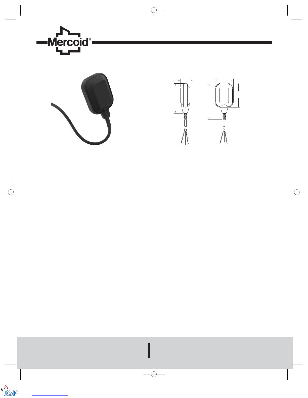
The Series CFS2 Cable Float Switch is a mechanically actuated floating switch
intended to activate electrical components, usually pumps, to start and stop
automatically. The CFS2 is perfect for simple level control of liquids for filling or
draining reservoirs and tanks. Float switches such as the CFS2 are the most
universally used for pump automation due to their high reliability, economical
pricing, and easy installation. Counterweights and cable hangers are available to
suit a variety of mounting applications. Optional cables available include those with
UL/CSA approval, higher chemical compatibility, high temperature durability, oil
resistance, and drinking water suitability. Contact factory for piggyback plug option,
gold contact switch option and cable length options ranging from 10 to 70 ft (3.04
to 21.34 m).
Series CFS2 Cable Float Switch
Specifications - Installation and Operating Instructions
Bulletin L-CFS2
DWYER INSTRUMENTS, INC.
Phone: 219/879-8000 www.dwyer-inst.com
P.O. BOX 373 • MICHIGAN CITY, INDIANA 46361, U.S.A. Fax: 219/872-9057 e-mail: info@dwyer-inst.com
SPECIFICATIONS
Service: Compatible liquids.
Wetted Materials:
Housing: Polypropylene;
Cable: CFS2-XXPXX-XX: PVC;
CFS2-XXNXX-XX: Neoprene;
CFS2-XXSXX-XX: 3x16 AWG SJOW;
CFS2-XXTXX-XX: Rubber compound EM7 quality ;
CFS2-XXWXX-XX: EPDM ethylene propylene.
Temperature Limits: 32 to 122°F (0 to 50°C).
Pressure Limits: 14.5 psi (1 bar).
Enclosure Rating: IP68.
Switch Type:
CFS2-DXXXX-XX: SPDT;
CFS2-CXXXX-XX: SPST;
CFS2-OXXXX-XX: SPST.
Electrical Rating:
CFS2-XXAXX-XX
10 (4) A @ 250 VAC;
CFS2-XXBXX-XX
10 (8)A @ 250 VAC;
CFS2-XXCXX-XX
10 (8)A @ 250 VAC;
10 (6)A @ 400 VAC;
CFS2-XXDXX-XX
1 HP @ 125 VAC 16 FLA;
2 HP @ 250 VAC 12 FLA;
CFS2-XXEXX-XX
0.05 A @ 250 VAC.
Shipping Weight:
Housing: 5.43 oz (154 g);
Cable: 0.77 oz (21.27 g) per foot.
Agency Approvals: CFS2-XGDSX-XX: UL and CSA approved, all others CE.
5-5/32
[131.00]
1-41/64
[41.50]
6-15/64
[158.50]
4-9/64
[105.00]
3-3/16
[81.00]
L-CFS2:SSS-1000 12/8/10 8:39 AM Page 1
Remote Site Products - 1-888-532-2706 - www.remotesiteproducts.com
http://www.remotesiteproducts.com/p-14404-Dwyer-Mercoid-CFS2-OGDSN-30-Mechanical-Float-Switch.aspx
Page 2
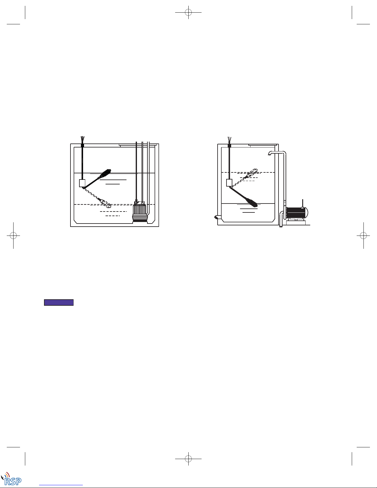
INSTALLATION INSTRUCTIONS
The basic operating principle of the CFS2 is very simple. As fluid level rises the float
will also rise, resulting in a tilt of the micro-switch located inside the housing. This tilt
will generate a signal that can be used to actuate a motor or signal an indicator alarm.
To ensure the proper function of the CFS2, it is necessary to secure the electric cable
inside the tank or well as illustrated in Figures 1 and 2. The length of the cable
measured between the fixture point and the body of the CFS2 determines the total
extension of the float and also the resulting distance between the pump stopping and
starting level. It is essential to ensure that there are no obstructions in the CFS2
operational area before operation. During operation, adjustments to the CFS2 cable
must not be made under any circumstances, due to the fact that any unwanted
cable connections made while the CFS2 is immersed in water can lead to electric
shock. There are two installation options for this cable float switch. One method is to
fix the cable of the CFS2 to the reservoir or container with the use of a small clamp,
another technique would be to attach the accessory A-457 counterweight to the cable
of the float switch a desired distance between the highest and lowest level desired.
Note: With the use of the counterweight, the length of cable between the float and
fixed point (starting and stopping indication) can be freely adjusted.
ELECTRICAL CONNECTIONS
The Series CFS2 features a variety of different cable options. One of these options
includes the selection between SPST and SPDT. SPST, single pole single throw,
allows a single operating function with the choice of operation on increasing level
(NC/filling) or operation on decreasing level (NO/emptying), depending on the model
selection. SPDT, single pole double throw allows for operation of both increasing and
decreasing level, depending on the connections made between the terminals of the
micro-switch and the cable. SPDT, which is a four-conductor cable (ground option) or
a three-conductor cable (without ground option), has one lead that is common, one
that is normally open (NO), and the other that is normally closed (NC), for the proper
connections of these conductors please refer to the wiring diagrams in Figures 3 to
12.
Figure 2-Filling
Figure 1-Empyting
When making the connections described above, ensure that the
maximum motor power does not exceed the values indicated on
the level switch. The power supply cable is an important part of the CFS2. Should the
cable appear to be damaged, discontinue use immediately and proceed to replace the
unit. The yellow/green wire found on some units is the ground wire and must be
connected to a suitable ground terminal with the dimension greater than 1 mm
2.
The
terminal used must also be protected against accidental break.
NOTICE
L-CFS2:SSS-1000 12/8/10 8:39 AM Page 2
Remote Site Products - 1-888-532-2706 - www.remotesiteproducts.com
http://www.remotesiteproducts.com/p-14404-Dwyer-Mercoid-CFS2-OGDSN-30-Mechanical-Float-Switch.aspx
Page 3

3 x 1 CABLE
BROWN
BLUE
L
N
COM
BROWN
BLUE
L
N
COM
BROWN
BLACK
L
N
COM
N.O.
N.C.
BLUE
BROWN
BLACK
L
N
COM
N.O.
N.C.
BLUE
YELLOW
GREEN
BROWN
BLUE
L
N
COM
YELLOW
GREEN
BROWN
BLUE
L
N
COM
BROWN
BLACK
L
N
COM
N.O.
N.C.
BLUE
YELLOW
GREEN
BROWN
BLACK
L
N
COM
N.O.
N.C.
BLUE
GREEN
YELLOW
GREEN
WHITE
BLACK
L
N
COM
GREEN
WHITE
BLACK
L
N
COM
CFS2-ONXXX-XX
CFS2-DNXXX-XX
CFS2-OGXXX-XX
CFS2-DGXXX-XX
Figure 11-Emptying (NO) Function
Figure 12-Filling (NC) Function
CFS2-DGXXX-XX
CFS2-CGXXX-XX
CFS2-DNXXX-XX
Figure 4-Filling (NC) Function
Figure 3-Emptying (NO) Function
Figure 5-Double Function (Emptying (NO))
Figure 7-Emptying (NO) Function
Figure 9-Double Function (Emptying (NO))
CFS2-CNXXX-XX
Figure 6-Double Function (Filling (NC))
Figure 8-Filling (NC) Function
Figure 10-Double Function (Filling (NC))
CFS2-OGESX-XX
CFS2-CGESX-XX
2 x 1 CABLE
3G1 CABLE
4G1 CABLE
SJOW 3 x 16 AWG CABLE (UL APPROVED)
Correctly insulate any wire not in use!
WIRING DIAGRAMS
L-CFS2:SSS-1000 12/8/10 8:39 AM Page 3
Remote Site Products - 1-888-532-2706 - www.remotesiteproducts.com
http://www.remotesiteproducts.com/p-14404-Dwyer-Mercoid-CFS2-OGDSN-30-Mechanical-Float-Switch.aspx
Page 4

INSTALLATION OF COUNTERWEIGHT
For correct counterweight installation, refer to the following procedure as well as
the illustration in Figure 13.
1. Insert the cable into the counterweight, turning it. This will result in the
detachment of the plastic ring inserted in the mouth (if necessary use a
screwdriver to aid in the detachment of the ring). Place the ring at the point on
the cable where the counterweight is to be attached.
2. Attach the counterweight on the ring by turning it and using moderate pressure.
(Counterweight sold separately).
MAINTENANCE & REPAIR
Inspect and clean wetted parts with water or damp cloth at regular intervals.
Disassembly or modifications made by the user will void the warranty and could
impair the continued safety of the product. If repair is required obtain a Return
Goods Authorization (RGA) number and send the unit, freight prepaid, to the
address below. Please include a detailed description of the problem and conditions
under which the problem was encountered.
Dwyer Instruments, Inc.
Attn: Repair Department
102 Indiana Hwy 212
Michigan City, IN 46361
DWYER INSTRUMENTS, INC.
Phone: 219/879-8000 www.dwyer-inst.com
P.O. BOX 373 • MICHIGAN CITY, INDIANA 46361, U.S.A. Fax: 219/872-9057 e-mail: info@dwyer-inst.com
©Copyright 2010 Dwyer Instruments, Inc. Printed in U.S.A. 12/10 FR# R3-443853-00
Figure 13-Counterweight Installation
L-CFS2:SSS-1000 12/8/10 8:39 AM Page 4
Remote Site Products - 1-888-532-2706 - www.remotesiteproducts.com
http://www.remotesiteproducts.com/p-14404-Dwyer-Mercoid-CFS2-OGDSN-30-Mechanical-Float-Switch.aspx
 Loading...