

Dwyer Instruments Capsuhelic 4000-100CM, Capsuhelic 4000 Series, Capsuhelic 4000-10KPA, Capsuhelic 4000-150CM, Capsuhelic 4000-125PA Installation And Operating Instructions Manual
...Page 1
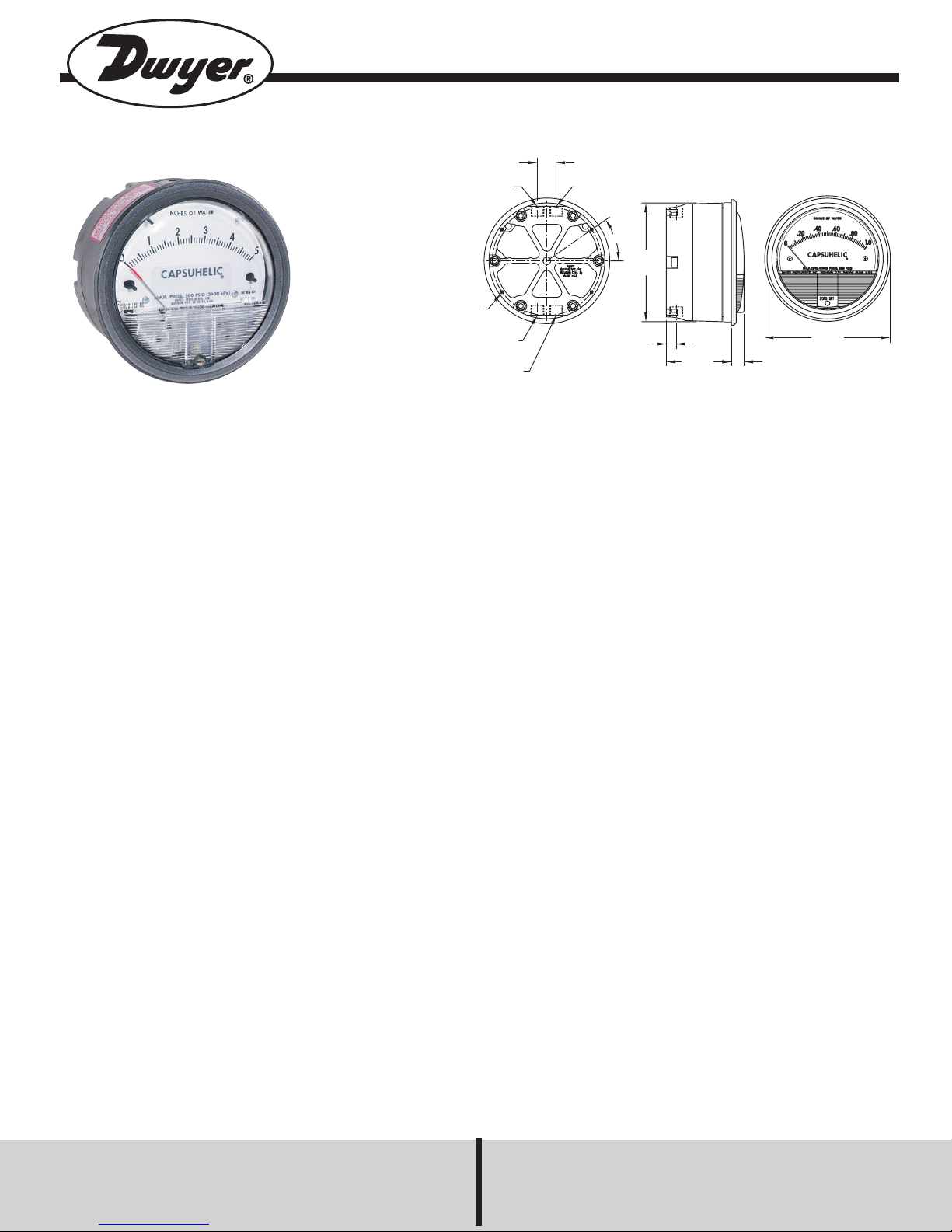
Series 4000 Capsuhelic®Differential Pressure Gage
1/4 FEMALE NPT LOW
PRESSURE CONNECTION
(AIR OR GAS)
35° TYP
13/32
[10.32] TYPE
2-19/32
[65.86]
1/2
[12.70]
Ø5
[127.00]
Ø4-45/64
[119.46]
3/4 [19.05] TYP
1/4 FEMALE NPT HIGH
PRESSURE CONNECTION
(AIR OR GAS)
(4) #6-32 X 3/8 [9.53] DP
HOLE ON A 4-11/32 [110.33]
BOLT CIRCLE
1/4 FEMALE NPT HIGH
PRESSURE CONNECTION
(LIQUID)
1/4 FEMALE NPT LOW
PRESSURE CONNECTION
(LIQUID)
Specifications - Installation and Operating Instructions
Bulletin A-32
CAUTION: Use of a line filter (Dwyer model A-391 or equiv-
alent) is recommended to prevent entry of liquid borne particles into gage. Dwyer Instruments cannot assume
responsibility for failure of gages due to clogging of internal
passages.
NOTE: DO NOT use with hydrogen gas. Toxic and/or explosive gas may form due to reaction with rare earth magnet.
®
CAPSUHELIC
INSTALLATION
1. Select a location free from excessive vibration and where
the ambient temperature will not exceed 200°F. Sensing
lines may be run any necessary distance. For example, 250
foot lines will not affect accuracy but will damp the reading
slightly. Do not restrict lines. If pulsating pressures or vibration cause excessive pointer oscillation, consult factory for
means of providing additional damping.
2. All standard models are calibrated for use with the
diaphragm and scale in a vertical position. Special factory
calibration is necessary for operation in an inclined or horizontal position. The exceptions are ranges under 5 in. w.c.,
(or metric equivalents) which can only be calibrated for vertical operation.
SPECIFICATIONS
Service: Aluminum Case: Air and compatible gases and
oil based liquids. Brass Case: Air and compatible gases
and water based liquids.
Wetted Materials: Consult factory.
Housing: Die cast aluminum with impregnated hard
coating, standard. Optional forged brass housing is
required for water or water based fluids. Special material
diaphragms available, contact factory.
Accuracy: ±3% of full scale at 70°F (21.1°C). (±2% on
4000S models, ±4% on 4200, 4210, 4215, 4220, 4300,
4400, and 4500).
Pressure Limits: -20˝ Hg to 500 psig.
(-0.677 bar to 34.4 bar).
Temperature Limits: 20 to 200°F. (-6.67 to 93.3°C).
Size: 4˝ (101.6 mm) diameter dial face.
Mounting Orientation: Diaphragm in vertical position.
Consult factory for other position orientations.
Process Connections: 1/4˝ female NPT high and low
pressure taps, duplicated -one pair top for air and gas,
and one pair bottom for liquids.
Weight: 3 lb, 3 oz (1.45 kg) aluminum case;
7 lb, 13 oz (3.54 kg) brass case.
Standard Accessories: Two 1/4˝ NPT plugs for duplicate
pressure taps, four flush mounting adapters with screws
and four surface mounting screws.
DWYER INSTRUMENTS, INC.
P.O. Box 373 • Michigan City, IN 46361, U.S.A. Fax: 219/872-9057 e-mail: info@dwyer-inst.com
Phone: 219/879-8000 www.dwyer-inst.com
Page 2

3. Surface Mounting
CAUTION
Note location of blowout or vent holes in the surface
mounting diagram. Do not block these holes as their function is to vent overpressure failure out the back of the gage
rather than blowing off the front cover.
Important Notes:
Two pairs of high and low pressure taps are provided, one
pair on the top and a duplicate pair on the bottom. These
fittings may be utilized according to the type of service for
which the gage will be used. For gas or vapor service the
gage should be connected from the pressure source to the
top pressure fittings so that any accumulation of condensate may be drained or bled out the bottom fittings. For liquid service the pressure source should bee connected to
the bottom taps so that any trapped gas may be vented out
the top fittings. Optional bleed fittings may be obtained to
1
replace the standard
/4NPT plugs for installations requiring
frequent draining or venting of the gage. Note that the
unused pair of pressure taps must be plugged in order for
the gage to operate. For straight pressure or vacuum applications where only one of a pair of high and low pressure
taps are being utilized, the other tap must be open to
atmosphere.
Locate 4 mounting holes, 35˚ from horizontal centerline on
a 4-11/32˝ dia. circle. Use No. 6-32 machine screws of
appropriate length. Be sure to drill 1/4˝ holes for blowout
protection as shown in the diagram.
4. Flush Mounting
Provide a 4-13/16˝ dia. opening in panel. Insert gage and
secure in place with No. 6-32 machine screws of appropriate length, with mounting lugs firmly secured in place.
5. To zero the gage after Installation
Set the indicating pointer exactly on the zero mark, using
the external zero adjust screw on the cover at the bottom.
Note that the zero check or adjustment can only be made
with the high and low pressure taps both open to atmosphere.
1
For portable use or temporary installation use
/4male NPT
to male flare fitting and connect to pressure source with
high pressure hose or tubing will flare nut connectors.
1
For permanent installation
/4˝ OD copper or stainless steel
tubing is recommended.
Proper installation of fittings and plugs is important.
Sparingly apply pipe thread sealant to threads. Excessive
amounts can fall into pressure passages and cause block-
®
age. we recommend Loctite
69-31 Hydraulic Sealant.
Install using torque wrench. Tighten only to 20 ft/lbs. Overtightening can damage case.
®
CAPSUHELIC
MAINTENANCE
Note: Capsuhelic®differential pressure gages are high pre-
cision instruments assembled and calibrated in a modern
factory. If trained instrument mechanics are not available,
we recommend that any instruments requiring repair be
returned to the factory.
1. No lubrication or periodic servicing is required. If the interior is protected from dust, dirt, corrosive gases and fluids,
years of trouble free service may be expected.
2. For service requiring a high degree of continued accuracy, periodic calibration checks are recommended. Send
back to the factory for re-calibration.
©Copyright 2003 Dwyer Instruments, Inc. Printed in U.S.A. 10/03 FR# 440306-00 Rev. 10
DWYER INSTRUMENTS, INC.
P.O. Box 373 • Michigan City, IN 46361, U.S.A. Fax: 219/872-9057 e-mail: info@dwyer-inst.com
Phone: 219/879-8000 www.dwyer-inst.com
 Loading...