

Page 1
Bulletin P-AVUL-M
3-3/16
31/32
24.58
[11.84]
®
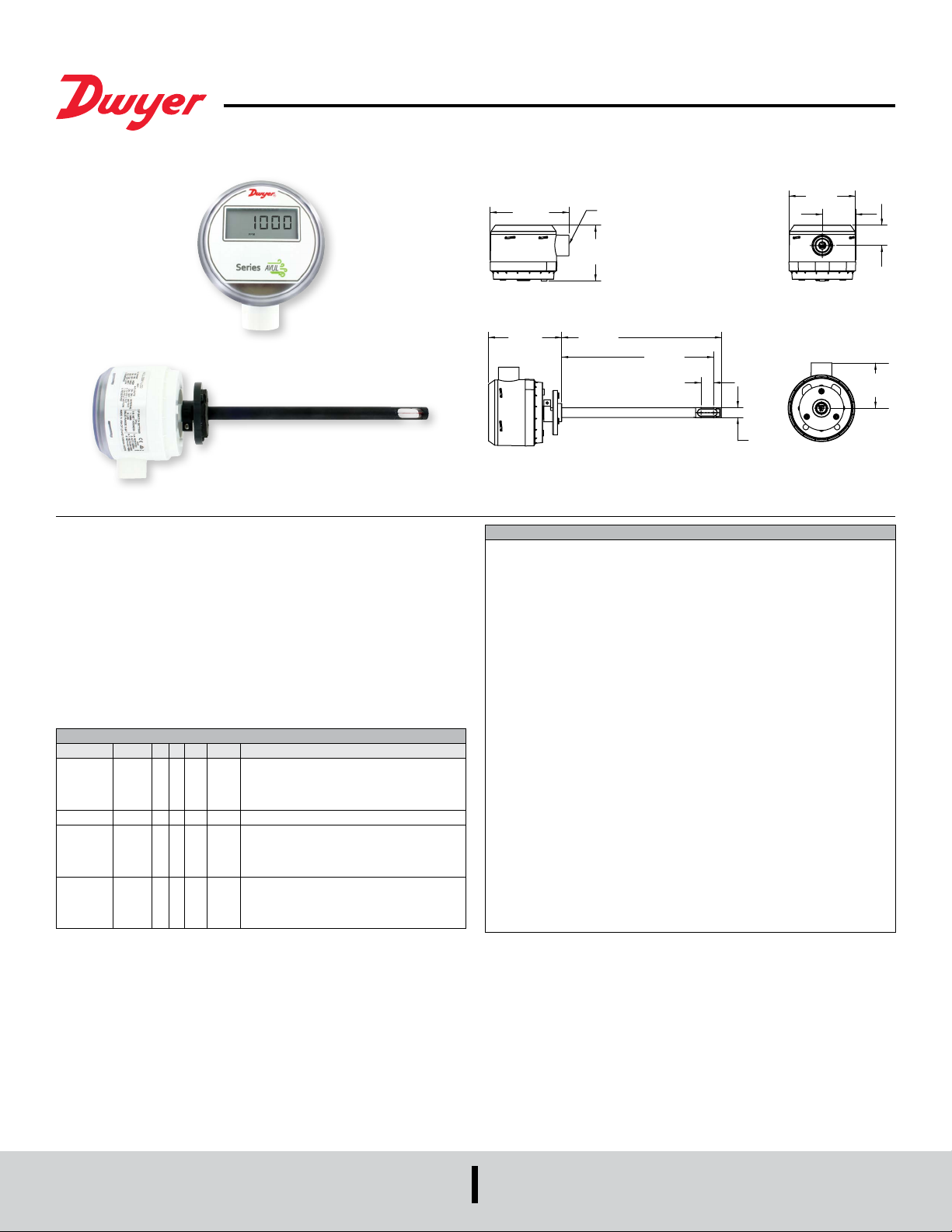
Series AVUL Air Velocity Transmitter with Modbus® Communication
Specications - Installation and Operating Instructions
The SERIES AVUL Air Velocity Transmitter quickly and accurately measures air
velocity or volumetric ow in imperial or metric units. Simultaneous current and
voltage outputs on all models provide universal inputs to monitoring equipment while
the output range, units, and 0 to 5/10 VDC output can be congured via local DIP
switches. The optional integral display, or the portable remote display tool, provide a
convenient way to locally monitor process values and congure the unit.
Models are available in 3% and 5% accuracy models to suit a variety of needs, and the
optional BACnet MS/TP or Modbus
to be daisy-chained while providing access to all of the velocity and ow data, as well
as additional information such as air temperature.
MODEL CHART
Model AVUL -3 D A1 -LCD AVUL-3DA1-LCD
Accuracy 5
3
Mounting D Duct mount
Output A1
Options LCD
®
RTU/ASCII communication protocol allows units
±(0.2 m/s + 5% of reading) @ standard
conditions
±(0.2 m/s + 3% of reading) @ standard
conditions
Analog universal (0 to 5 VDC, 0 to 10 VDC,
B1
M1
4 to 20 mA)
Analog + BACnet MS/TP
Analog + Modbus
LCD display
FC
Factory calibration certicate
NIST
NIST certicate
GLD
Electrical cable gland
®
RTU/ASCII
3-49/64
[95.71]
3-33/64
[89.13]
SPECIFICATIONS
Service: Clean air and non-combustible, compatible gases.
Wetted Materials: Consult Factory.
Range: 1000, 2000, 3000, 4000 FPM (5, 10, 15, 20 m/s); Field selectable.
Accuracy: ±(5% of reading + 0.2 m/s) or ±(3% of reading + 0.2 m/s) @ standard
conditions, depending on model.
Temperature Limits: 32 to 122°F (0 to 50°C).
Power Requirements: 24 VDC ±20% or 24 VAC ±20%.
Humidity Limits: 5 to 95% RH, non-condensing.
Output Signals: 4 to 20 mA, 0 to 5 VDC, 0 to 10 VDC .
Response Time (90%): 10 seconds, typical.
Zero & Span Adjustments: Digital push buttons.
Output Load Resistance: Current Output: 0 to 1100 Ω max.; Voltage Output:
Minimum load resistance 1 kΩ.
Current Consumption: 60 mA Max.
Display (optional): 5 Digit LCD.
Electrical Connections (Analog): Power and output: four wire removable
European style terminal block for 16 to 26 AWG.
Communication (optional): Connections: BACnet MS/TP or Modbus
three wire removable European style terminal block for 16 to 26 AWG; Supported
Baud Rates: 9600, 19200, 38400, 57600, 76800, 115200.
Device Load: 1/8th unit load.
Electrical Entry: 1/2˝ NPS thread. Accessory (A-151): Cable gland for 5 to 10 mm
diameter cable.
Enclosure Rating: NEMA 4X (IP66).
Mounting Orientation: Flow direction must be parallel to the sensor tip;
See Installation section for details.
Weight: 6.0 oz (160 g).
Agency Approval: CE, RoHS.
1/2 NPS
2-43/64
[67.92]
7-41/64
[194.07]
7-17/64
[184.60]
39/64
[15.32]
Ø15/32
[80.81]
1-19/32
[40.59]
®
RTU/ASCII:
2-5/32
[54.82]
DWYER INSTRUMENTS, INC.
P.O. BOX 373 • MICHIGAN CITY, INDIANA 46360, U.S.A.
Phone: 219/879-8000
Fax: 219/872-9057
www.dwyer-inst.com
e-mail: info@dwyermail.com
Page 2
INSTALLATION
Duct Mount:
The transmitter should be mounted away from fans, corners, heating and cooling
coils, and other equipment that will effect the measurement of the air velocity. It
is recommended that the AVUL is mounted 10 duct diameters downstream of any
disturbances and 5 duct diameters upstream of any disturbances, if possible.
1. Mark and drill a 0.750-0.938˝ (20-24 mm) diameter hole into the duct.
2. Insert and center the duct mount ange in the previously drilled hole and mark
location of the three mounting screw holes.
3. Remove the mounting ange and drill or punch the mounting holes in the marked
locations.
4. Fasten the ange to the duct using three #8 x 1/2 pan head sheet metal screws. Do
not over tighten screws.
5. Insert the AVUL probe into the ducts mount ange and set the desired insertion
depth.
6. Note the ow direction and unit alignment as shown on sensor tip and product label,
tighten probe retention set screw on the duct mount ange screw to afx the probe in
place.
Electrical Connection:
The Series AVUL is powered and simultaneously transmits a two-wire 4 to 20 mA
current output and a three-wire 0 to 5 VDC or 0 to 10 VDC voltage output via a
removable four conductor terminal block. The transmitter power supply common is
used to reference the current and voltage outputs so either current, voltage, or current
and voltage may be wired according to the application. The range of the voltage output
can be selected using the on board DIP switches as described in the Analog DIP
Switch Settings section of this manual.
Power Supply
Choose a power supply with a voltage and current rating sufcient to meet the power
specications under all operating conditions. If the power supply is unregulated, make
sure the output voltage remains within the required voltage range under all power line
conditions. Ripple on the supply should not exceed 100 mV.
Although low loop resistances are recommended, the absolute maximum current loop
load resistance, R
R
MAX = (VPS – 2.0) / 0.02 where VPS is the power supply voltage
For a 24 VDC nominal power supply, this evaluates to R
MAX , is dened by the following the equation:
MAX = 1100 ohms.
Shielded two wire cable is recommended for current output loop wiring. Ground the
shield at the power supply end only.
The maximum length of connecting wire between the current transmitter and the
receiver is a function of wire size and receiver resistance. That portion of the total
current loop resistance represented by the resistance of the connecting wires
themselves should not exceed 10% of the receiver resistance. For extremely long
runs (over 1,000 ft.), it is desirable to select receivers with higher resistances in order
to keep the size and cost of the connecting leads as low as possible. In installations
where the connecting run is no more than 100 ft, connecting lead wire as small as No.
22 Ga. can be used.
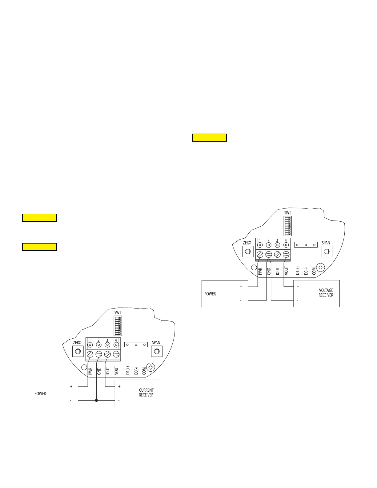
Voltage Output Operation
CAUTION
DO NOT EXCEED SPECIFIED SUPPLY VOLTAGE RATINGS.
PERMANENT DAMAGE NOT COVERED BY WARRANTY WILL
RESULT.
The terminal block is removable, and each of the terminals are labeled underneath the
terminal block on the circuit board. The voltage output and the power supply must have
separate wire leads that are only joined at terminal 2 of the transmitter, as shown in
Figure 2. Additional error may occur for the voltage output if a single wire is used or if
the wires are joined at the power supply or receiver. The connections to the transmitter
are made to terminals 1, 2, and 4 (PWR, GND, and VOUT respectively) on the terminal
block as shown in Figure 4.
CAUTION
DO NOT EXCEED SPECIFIED SUPPLY VOLTAGE RATINGS.
PERMANENT DAMAGE NOT COVERED BY WARRANTY WILL
RESULT.
Current Output Operation
CAUTION
DO NOT EXCEED SPECIFIED SUPPLY VOLTAGE RATINGS.
PERMANENT DAMAGE NOT COVERED BY WARRANTY WILL
RESULT.
The terminal block is removable, and each of the terminals are labeled underneath
the terminal block on the circuit board. As the power supply and outputs share the
same common signal (GND), the outputs may have separate wires but must effectively
join at terminal 2 of the transmitter, as shown in Figure 1. The connections to the
transmitter are made to terminals 1, 2, and 3 (PWR, GND, and IOUT respectively) on
the terminal block as shown in Figure 4.
Figure 2
Voltage Output Wiring
The minimum receiver load is 1 kΩ. The resistance due to the wire should be low
compared to the receiver load resistance. While the voltage at the terminal block
remains unchanged with a 10 mA current ow, resistive losses in the wiring do cause
errors in the voltage delivered to the receiver. For a 1% accurate gauge, the resistance
of the wires should be less than 0.1% of the value of the receiver load resistance. This
will keep the error caused by the current ow below 0.1%.
The output across VOUT and COM will be either 0 to 5 VDC, 0 to 10 VDC, or the
inverse depending on the DIP switch setting. See the Analog DIP Switch Settings
section for more information.
Figure 1
Current Output Wiring
Page 3
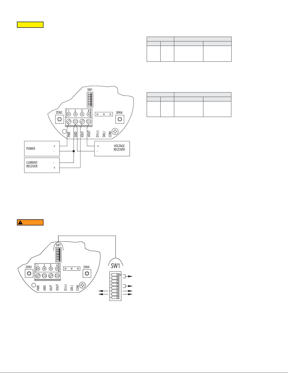
Simultaneous Current and Voltage Output Operation
RANGE
CAUTION
DO NOT EXCEED SPECIFIED SUPPLY VOLTAGE RATINGS.
PERMANENT DAMAGE NOT COVERED BY WARRANTY WILL
RESULT.
The terminal block is removable, and each of the terminals are labeled underneath the
terminal block on the circuit board. The voltage output and the power supply must have
separate wire leads that are only joined at terminal 2 of the transmitter, as shown in
Figure 3. Additional error may occur for the voltage output if a single wire is used or if
the wires are joined at the power supply or receiver. The connections to the transmitter
are made to terminals 1, 2, 3 and 4 (PWR, GND, IOUT, and VOUT respectively) on
the terminal block as shown in Figure 4, which reects both the 4-20 mA and 0-5/10
VDC outputs in the same circuit. Details of each output are detailed in their electrical
connection sections.
Setting the Air Velocity Range
The range of the instrument is selected by using DIP switches 1 and 2 on SW1. Table
1 shows the maximum full scale value for the selected range and unit. Refer to Setting
the Engineering Units section for information on setting the unit.
DIP Switch SW1 Full Scale Range
1 2 Imperial (FPM) Metric (m/s)
ON
ON
ON
OFF
OFF
OFF
ON
OFF
4000
3000
2000
1000
20
15
10
5
Table 1: DIP Switch SW1 Settings for Full Scale Range
Setting the Engineering Units
The Series AVUL can be congured to indicate velocity in imperial (FPM, CFM) or
metric (m/s, m
3
/h) units using DIP switches 4 and 5 on SW1, and Table 2 shows the
values. The units will be displayed on the optional LCD display if connected.
DIP Switch SW1 Units
4 5 Velocity Mode Air Flow Mode
ON
ON
ON
OFF
OFF
OFF
ON
OFF
FPM
m/s
m/s
m/s
CFM
3
m
3
m
3
m
/h
/h
/h
Table 2: DIP Switch SW1 Settings for Units
The default operating mode is velocity, but changes can be made, such as ow
mode, via the menu system while an optional display or remote display accessory is
connected. Please refer to Appendix VI for a full menu ow chart.
Setting the Output Voltage Range
Voltage Output can be either 0 to 5 VDC or 0 to 10 VDC depending on the position of
DIP Switch 6 ON SW1.
Simultaneous Current and Voltage Output Wiring
Figure 3
ANALOG DIP SWITCH SETTINGS
The analog output DIP switches (SW1) are located above the terminal blocks on the
left are as shown in Figure 4. A small screw driver or pen can be used to change the
position of the switches as required.
WARNING
All power should be turned off to the transmitter before adjusting
the DIP switch settings to avoid electrical shock.
UNITS
5V
REV
10V
DIR
• When the switch is in the ON position, the output will be 0 to 10 VDC.
• When the switch is in the OFF position, the output will be 0 to 5 VDC.
Setting the Input / Output Action
The output will either follow the process directly (DIRECT) or inverted (REVERSED)
based on the position of DIP Switch 7 on SW1.
• When the switch is in the ON position, the output directly follows the input (i.e. output
increases as the input increases).
• When the switch is in the OFF position, the output acts in reverse of the input (i.e.
output decreases as the input increases).
Figure 4
Analog Dip Switches
Factory Default Settings (DIP SW1 – All Switches ON)
Range = Highest Range Setting (4000 FPM)
Units = Imperial (FPM)
Voltage Output Range = 0 to 10 VDC
Direct / Reverse Output Action = Direct
KEY
Page 4
CALIBRATION
NOTICE
takes place. This delay is used to reduce vibration or disturbances of the user related
to the button presses.
There is a 5 second delay from the time the zero or span calibration
buttons are released until the time that the change in calibration
NOTICE
adjusted by the user.
Zero Calibration
The zero calibration can be set by covering the sensor to ensure no air ow and
pressing the zero button for 3 seconds. If either the remote or local LCD is present, the
display will read ZEro and then sequence back to the home display.
SPAN Calibration
The span calibration can be adjusted only after setting the zero adjustment. It must
be completed within 5 minutes of the last zero calibration. The span calibration button
will be ignored until the zero calibration is completed. Place the sensor in airow that
matches the maximum selected range of the transmitter. Press and hold the span
button for 3 seconds. If either the remote or local LCD is present, the display will read
SPAn and then sequence back to the home display. If the span calibration is attempted
before adjusting the zero calibration, the FAiL error message will be displayed briey
before returning to the home display.
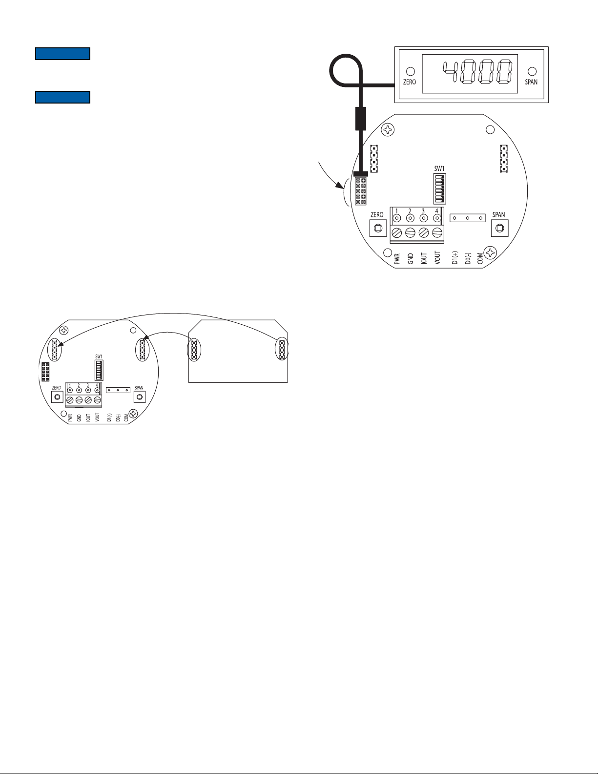
LCD Display
The Series AVUL can be ordered with an optional, integral LCD. It comes with a
housing cover and overlay to protect the display. The display will plug into the pins as
shown in Figure 5. If the display is not needed for normal operation, the transmitter can
be ordered without the LCD.
The security level that is set in the Programming Menu section
of the manual will determine which calibrations, if any, may be
Figure 6
Remote Display Diagram
Display Error Messages
ovEr = The air velocity is greater than the maximum span value causing an Over
Range Error
UndEr = The air velocity is less than the minimum span value causing an Under Range
Error
FAiL = When the span or zero buttons are pressed, the air velocity value is out of the
range to allow a correct setting. This may be due to a sensor failure.
Err1 = The sensor is damaged.
Pluggable Display Diagram
Figure 5
Another option for models that do not have a display would be to use a Model A-435-A
remote display tool which can plug into the connector shown in Figure 6. The remote
display tool has two buttons that function identically to the buttons on the PCB.
PROGRAMMING MENUS
Home Menu
During normal operation, the display will be in the Home Menu and will display the
current measured pressure and the engineering units.
Menu Access Security
While in the Home Menu, press and hold the Zero and Span buttons simultaneously
until SECUr appears on the display in order to access the other programming menus.
Upon releasing the buttons, the display will indicate the current security level.
If the current security level is the security level desired (i.e. Security Level 0), press
and hold the span button for 3 seconds to enter the Velocity or Air Flow Menu.
If the security level is not the desired level, the security level can be changed
temporarily to a lower security level or permanently to a higher level of security by
pressing the zero button. A security code will appear on the display, and it can be
changed to one of the codes listed in Table 3. The span button chooses which digit
and the zero button increments the value of that digit. Pressing and holding the span
button will store the value.
The level of access to the programming menus and the calibration is limited based on
the security level. Table 3 details the level of access for each security level.
Page 5

Security
Level Setting
0
1
2
3
Access
View Menu Edit Menu Span Zero
000
111
222
333
Yes
Yes
No
No
Yes
No
No
No
Yes
No
No
No
Yes
Yes
No
No
Table 3: Security Settings
Mode Selection / Digital Dampening Menu
From the home display, pressing the span and zero button simultaneously for 3
seconds will access the Menu Security Level. If the level is set to 0 or 1, pressing and
holding the span button for 3 seconds, a second time, will access the Mode Selection
Menu. The display will default to air velocity when rst powered up. Pressing the zero
button will cycle to air ow.
Once the desired mode is displayed, pressing and holding the span button for 3
seconds will save the selected mode and display the digital dampening or averaging
parameter. This parameter stabilizes the output and the display by averaging the
readings. There are 2.5 readings taken each second and the user can select the
number of seconds that they would like to average, up to 240 seconds. The display
and the output will continue to update at a rate of 2.5 updates per second, but the
moving average is used for these updates.
Velocity Mode
K-Factor Adjustment
If the Velocity Mode was selected, pressing and holding the span after adjusting the
digital dampening will enter the Velocity Mode and the transmitter will display the
engineering unit that has been selected by the DIP switch. Pressing and holding the
span button for 3 seconds will enter the K – Factor adjustment. The K – Factor can
be adjusted between 0.001 to 9.999. The K-Factor can be adjusted by pressing the
span button to select the digit and pressing the zero button to increment the value of
the digit. Pressing and holding the span button for 3 seconds will enter the Maximum
Output Adjustment parameter.
Flow Mode
K-Factor Adjustment
If the Flow Mode was selected, pressing and holding the span after adjusting the digital
dampening will enter the Flow Mode and the transmitter will display the engineering
unit that has been selected by the DIP switch. Pressing and holding the span button for
3 seconds will enter the K–Factor adjustment. The K–Factor can be adjusted between
0.001 to 9.999. The K-Factor can be adjusted by pressing the span button to select
the digit and pressing the zero button to increment the value of the digit. Pressing and
holding the span button for 3 seconds will enter the Area Adjustment parameter.
Area Adjustment
For ow applications, the area is multiplied by the velocity to determine the volumetric
air ow. The area will be listed in either CFM or m
3
/h depending on the DIP switch
settings. The units will appear on the display at the time of adjustment. The area can
be adjusted by pressing the span button to select the digit and pressing the zero button
to increment the value of the digit. Pressing and holding the span button for 3 seconds
will enter the Maximum Output Adjustment parameter.
Maximum Output Adjustment
The maximum output can be equivalent to air velocity or air ow. After adjusting
the K-Factor, the display will indicate if the adjustment is set for velocity or air ow.
Pressing the zero button will toggle between the selections. Pressing and holding the
span button for 3 seconds will enter the maximum output adjustment. The maximum
output can be adjusted by pressing the span button to select the digit and pressing the
zero button to increment the value of the digit. Pressing and holding the span button
for 3 seconds will save this value and go to the Security Update Menu.
Security Update / Save Changes Menu
The Security Update Menu allows the security level to be set either higher or lower
than the current security level setting. This security level will be displayed the next
time the Menus are accessed from the home screen. Pressing the zero button cycles
through the security levels. Pressing and holding the span button for 3 seconds
accepts the new security level and gives the option to save all the menu changes.
Pressing the zero button will toggle between yes and no. Yes will save the changes
made to all menu items and no will discard all the changes made to all menu items. If
the display is set to yes, pressing and holding the span will save the menu items and
return the display to the home position.
FACTORY DEFAULT PROCEDURE
In order to reset all of the menu settings back to their factory programmed values,
press and hold both the span and zero buttons simultaneously for 10 seconds until
FACt is displayed on the LCD. Upon releasing the buttons, the unit will be factory
defaulted. Since resetting the transmitter will wipe out all changes, it is necessary to
zero (and possibly span) the transmitter before taking measurements.
MAINTENANCE/REPAIR
Upon nal installation of the Series AVUL Air Velocity Transmitter, no routine
maintenance is required besides zeroing the transmitter occasionally. Besides routine
calibration and installation of the LCD, the Series AVUL is not eld serviceable, and
it is not possible to repair the unit. Field repair should not be attempted and may void
warranty.
WARRANTY/RETURN
Refer to “Terms and Conditions of Sales” in our catalog and on our website. Contact
customer service to receive a Return Goods Authorization number before shipping the
product back for repair. Be sure to include a brief description of the problem plus any
additional application notes.
APPENDIX I: Air Velocity / Air Flow Calculations
Velocity in m/s is then calculated from the equation:
Velocity (m/s) = Velocity (FPM) x 0.00508
3
Flow in m
Flow (CFM) = Area (ft
Flow (m
/h is then calculated using the below equation:
3
/h) = Flow (CFM) x 1.6992
2
) x K-Factor x Velocity (FPM)
APPENDIX II: Maximum Flow
Max Flow Max K Factor x Area
CFM m
3
/h CFM Range m3/h Range
5885000 9999000 1471.25 138.875
Table 4: Maximum Flow Values
APPENDIX III: Modbus
NOTICE
®
Communication Protocol Operation
Wiring should comply with Electrical Characteristics of
Generators and Receivers for Use in Balanced Digital Multipoint
Systems, TIA/EIA-485-A-1998, Telecommunications Industry Association, 1998.
NOTICE
Wiring should comply with Modbus® Communication Protocol
over Serial Line Specication and Implementation Guide V1.02,
Modbus Organization, Inc., 2006
NOTICE
Communications wiring must be in a daisy-chain fashion. Star
connections are not permitted.
NOTICE
Cable shield must be connected to earth ground at one location
only.
Figure 7 shows how to connect the AVUL in a network containing a common power
supply. Use a cable containing two twisted pairs. One pair is to be used for D1(+)
and D0(-). The other pair is to be used for power and common. This conguration is
not suitable for AC supplies. Use a DC supply only. Care should be taken that there
are not too many devices powered from the same supply as voltage drops will occur
in the wiring. If you have many devices, or have long cable runs, the local supply
conguration may be a better choice.
Figure 8 shows how to connect the AVUL in a network containing individual local
supplies. Use a cable containing a twisted pair and a single conductor. The pair is to
be used for D1(+) and D0(-). The single conductor is to be used for common. Both AC
and DC supplies are suitable for this conguration.
In either conguration you must use shielded cable. The AVUL has a shield terminal
for a convenient location to make connections. It is not electrically connected to the
AVUL. Connect the shield to earth ground at one location only to prevent ground loops.
All devices in the network should be daisy chained. Star connections and T
connections are not permitted.
The D1(+) and D0(-) lines must be terminated at both ends with a 120 ohm resistor. If
the AVUL is an end device it has an on-board resistor that may be used. See Modbus®
Communication Protocol DIP Switch Settings to enable it.
The network must be biased properly. If needed, there are bias resistors on-board the
AVUL. No more than two sets of bias resistors should be enabled in the network. See
®
Communication Protocol DIP Switch Settings to enable them.
Modbus
Page 6

PWR GND IOUT VOUT
NEXT
TO
PREVIOUS
D1(+) D0(-)COM
D1(+)
D1(+)
D0(-)
COM
SUPPLY
PWR GND IOUT VOUT D1(+) D0(-) COM
KEY:
DEVICE
D1(+)
D0(-)
PWR
COM
TO
DEVICE
D1(+)
D0(-)
PWR
COM
®
APPENDIX IV: Programming Via Modbus
Communication Protocol
Modbus® Mode Supported Baud Rates Data Size Parity Stop Bits
RTU 9600
19200
8 Even
38400
57600
ASCII 7 Even
76800
115200
Odd
1
None
None 2
Odd
1
1
None 2
Table 6: Supported Modbus
®
Communication Protocol Congurations
Figure 7
Common Power Supply
D0(-)
COM
+ -
POWER
Figure 8
Local Power Supply
Modbus® Communication Protocol DIP Switch Settings
Use the middle DIP Switch SW2 to congure the Modbus
®
Communication Protocol
address of the device. The LCD will show the address when the transmitter is powered
on. Valid addresses range from 1 to 247. By default, the device is shipped with the
address 127 (as shown in Figure 10). A valid and unused address should be set before
connecting to an existing network. However, the address can be changed while the
device is operational. If the address is changed, the device will stop responding to the
currently congured address immediately. The device waits 15 seconds after the last
switch change before applying the new address. The device will not function properly
if an invalid address is set. The red LED will periodically blink once indicating an invalid
address. The LCD will display A Err when the transmitter is powered on if the address
is invalid. See Appendix V for setting the Modbus
®
Communication Protocol address
of the device. Use the right DIP Switch SW3 to congure other hardware and software
options.
SW2
BIAS
RESISTOR
128 - MSB
32
AUTO SERIAL
CONFIGURATION
TERMINATING
RESISTOR
64
16
8
2
4
1 - LSB
Figure 9
Intelligent Serial Conguration
Intelligent serial conguration enables the device to determine the baud rate, data
size, party, stop bits and even the Modbus
from the serial trafc. This allows the Series AVUL to be quickly and easily deployed
after a valid Modbus
®
Communication Protocol address is chosen.
To activate intelligent serial conguration, set a valid Modbus
®
Communication Protocol mode directly
®
Communication Protocol
address using the left DIP switch SW2, connect the serial bus and power wires, and
then apply power. The device will power up and begin examining the serial bus for
communication. The Red LED will repeatedly ash twice, indicating that intelligent
serial conguration is in progress.
If the device is setup ofine or away from the main network, it is necessary to
generate Modbus
communication. Attempting to read input registers is a good method to generate
®
Modbus
®
Communication Protocol trafc in order to congure the serial
Communication Protocol trafc. Note that while serial conguration is in
progress, the device may not respond to requests. The device may require multiple
read requests to complete the serial conguration process.
The intelligent serial conguration process will complete once a message addressed
to the device is received and processed successfully. The serial conguration
parameters are then saved to non-volatile storage and loaded by default each time the
device starts. If the serial conguration of the bus changes, a power cycle of the device
is required to restart the Intelligent Serial Conguration process.
Function Name Function Code
Read Coils
Read Holding Registers
Read Input Registers
Write Single Coil
Write Single Register
Write Multiple Registers
Table 7: Supported Modbus
01
03
04
05
06
16
®
Communication Protocol Functions
The String data type is read as a stream of ASCII characters, with the rst character
sent in the MSB of the rst register, and the second character sent in the LSB of the
rst register and so on. If the string is shorter than the allotted size, the remaining bytes
will be zero padded.
Multi-
Address
Register Description Data Type Value Range
0001 –
0002
0003 –
0004
Register
Velocity
Flow Area
(ft2)
Velocity
Flow Area
(m2)
Description
Float
Float
Data Type
0.01…999.99
0.00093…92.9
Value
0.01…999.99
0.00093…92.9
Range
Supported
Yes
Yes
Multi-
Address
Supported
Table 8: Holding Registers
Switch On Off
1-2 – Display Units Selection
3-4 – Reserved
5 - Intelligent Serial
Conguration
6 – D1(+) Network resistor
7 – D0(-) Network resistor
8 – Terminating resistor
Enabled
511Ω Pull-up to 5V
511Ω Pull-down to GND
120Ω between D0(-) and
D1(+)
Disabled
Pull-up not connected
Pull-down not
connected
Open
Table 5: DIP Switch SW3 Functions
1 - The serial conguration, no parity with one stop bit is not ofcially supported by the
®
Communication Protocol standard. However, if this conguration is desired,
Modbus
set switch 5 on DIP switch SW3 to off. The device will congure itself in Modbus
®
RTU
Communication Protocol mode with a data size of 8, no parity, and 1 stop bit. The baud
rate will still be determined automatically.
Page 7

Coils
The coil registers represent functions of the device. The value returned when reading
a coil register indicates the status of the last function execution. If the value is 1, then
the last time the function executed was a success. If the value is 0, then the function
has either not been executed since power on or failed during the last execution. To
execute a function, write 1 to the corresponding register. A response will be returned
immediately and the value of the coil will be set to 0. Once the function completes,
the value of the coil will be set to 1 if the operation was a success. An application
should poll the value of the coil periodically during this time to determine if the function
succeeded. If the coil value does not transition to 1 after at most 10 seconds, then the
operation failed.
Multi-
Address
Register Description Data Type Value Range
0001
0002
0003
0004
Perform Zero Function
Perform Span Function
Reset Factory Defaults
Reset Device
Boolean
Boolean
Boolean
Boolean
0…1
0…1
0…1
0…1
False – True
False – True
False – True
False – True
Supported
No
No
No
No
Table 9: Coils
Coil 1 – Zero Function
The zero function will attempt to recalibrate the zero point. This may be needed if the
sensor has drifted over time. Note that the zero function will only re-zero the sensor
if the current air velocity is within ±2% of span air velocity of the previous zero. If the
current air velocity is outside the valid band, the zero function will fail and the coil value
will remain 0. If the sensor has drifted far enough that the zero function fails, then the
unit will have to be placed in ow to bring the current air velocity closer to the current
zero, and the zero function will have to be executed multiple times until the actual zero
is reached.
Coil 2 – Span Function
The span function will attempt to recalibrate the maximum air velocity. Note that
accurate span air velocity depends on an accurate zero air velocity. The span function
will fail if the zero function has not been executed within the last 5 minutes.
Coil 3 – Reset factory Defaults Function
The reset factory defaults function resets the zero, span, Velocity K value, Area, and
Use Default K Value variables back to their factory default values.
Coil 4 – Reset Device Function
The reset device function allows this device to be reset remotely from the Modbus
Communication Protocol. When the reset device function coil is written with a value
of 1, the device will immediately respond with success. The reset will take place
approximately 5 seconds after the command was received. Writing the value 0 to this
coil has no effect.
Multi-address Support
Multi-Address support allows a register to be read or written to using different byte
orientations specied by the address range. For example, input register 0003 can also
be read at 2003, 4003 and 6003 with different byte orientations as listed in Table 10.
Registers that do not have multi-address support are only available in Big-Endian byte
orientation (Modbus
®
Communication Protocol standard).
Float/32 Bit Values 16 Bit Values
Register 1 Register 2 Register 1
Byte Order Address Range MSB LSB MSB LSB
Big-Endian
Byte Swap
Word Sway
Little-Endian
1 – 2000
2001 – 4000
4001 – 6000
6001 - 8000
A
B
C
D
A
B
A
D
C
D
D
C
C
A
B
B
A
B
B
A
A
B
B
A
Table 10: Multi-Address Support
®
APPENDIX V: Setting Modbus
Communication Protocol MAC Address of Unit
Switch Position 1 2 3 4 5 6 7 8
Address Value 128 64 32 16 8 4 2 1
Table 11: Device Objects
The address assignment is determined by adding the values for each of the switches
that are in the ON position. The transmitter comes from the factory with all of the DIP
switches, except position 1, in the ON position as shown in Figure 10. The address
of the transmitter would be 127 as it would be 64+32+16+8+4+2+1 = 127. Another
example would be if the address desired was 008, the only DIP switch position in the
ON position would be position 5 as shown in Figure 11
.
ON
12345678
Figure 10
Figure 11
NOTICE
possible address would be address 255 when all of the DIP switches were set to ON,
but the transmitter only has valid address from 1 to 247. Any address outside of this
range will give an error code.
APPENDIX VI: Modbus
Register Description Data Type Value Range
0001
0002
0003
®
0004
0005
0006
0007 –
0008
0009 –
0010
0011 –
0012
0013 –
0014
0015 –
0016
0017 –
0018
0019
0020 –
0021
8001 –
8006
8007 –
8012
8013 –
8018
8019 –
8024
Though the minimum possible address would be address 0 when
all the DIP switch positions were set to OFF, and the maximum
®
Communication Protocol Registers
Velocity (FPM)
Velocity (0.001 MPS)
Flow (CFM)
Flow (CMH)
Temperature (0.1 °F)
Temperature (0.1 °C)
Velocity (FPM)
Velocity (MPS)
Flow (CFM)
Flow (CMH)
Temperature (°F)
Temperature (°C)
Sensor Operational
Sensor
Communication
Errors
®
Application
Modbus
Firmware Version
Sensor Application
Firmware Version
®
Application
Modbus
Serial Number
Sensor Application
Serial Number
Table 12: Modbus
Signed 16bit
integer
Signed 16bit
integer
Signed 16bit
integer
Signed 16bit
integer
Signed 16bit
integer
Signed 16bit
integer
Float
Float
Float
Float
Float
Float
Unsigned 16bit
integer
Unsigned 32bit
integer
0…1
0…2
String
String
String
String
®
Communication Protocol Registers
False –
True
32
-1
0…2321
Multi-
Address
Supported
Yes
Yes
Yes
Yes
Yes
Yes
Yes
Yes
Yes
Yes
Yes
Yes
Yes
Yes
No
No
No
No
Page 8

APPENDIX III: Menu Flow Chart
BUTTON PRESS LEGEND
MENU CONVENTIONS
ZERO
SPAN
ZERO
SPAN
ZERO
SPAN
Averaging Menu
= PRESS ZERO BUTTON
= PRESS SPAN BUTTON
= PRESS AND HOLD ZERO BUTTON
= PRESS AND HOLD SPAN BUTTON
= PRESS AND HOLD ZERO AND SPAN BUTTONS
SECURITY LEVEL
SELECTION
IN HOME POSITION:
CALIBRATE UNIT TO ZERO PRESSURE.
ZERO
CALIBRATE UNIT TO SPAN PRESSURE.
SPAN
ZERO
ENTER MENU DISPLAY
SPAN
IN MENU DISPLAY:
SEQUENCES TO NEXT MAIN MENU ITEM, AND IF A MENU ITEM IS CHANGED TEMPORARILY SAVES THE SELECTION
SPAN
SEQUENCES THROUGH SUB MENU SELECTIONS OR INCREMENTS DIGITS
ZERO
SEQUENCE TO NEXT DIGIT. ACTIVE DIGIT WILL BLINK.
SPAN
HOME POSITION
ZERO
SPAN
WHILE BUTTONS ARE
PRESSED
WHEN BUTTONS ARE
RELEASED DISPLAYS CURRENT
SECURITY LEVEL
ZERO
TO CHANGE
SECURITY LEVEL
SPAN SPAN
IF SECURITY IS SET TO
0, 1, OR 2
ZERO
SPAN
IF SECURITY IS SET TO 3
DISPLAY IS NOT NECESSARY
FACTORY SETTINGS
HOLD 7
SECONDSTO HOME POSITION
RESTORED, THEN RE TURNS
ZERO
SPAN
INCREMENT
DIGIT
SELECT
DIGIT
SECURITY LEVEL SETTING
0000
1111
2222
3333
HOME POSITION
= BLINKING DIGIT
USE DEFAULT DIP
SWITCH SETTINGS
MODE SELECTION
VELOCITY OR FLOW
ADJUST AVERAGING
TO "VELOCITY OR FLOW" MENUS
PRESS ANY KEY
OR WAIT 5 SECONDS
ZERO SPAN
ZEROSPAN
ZERO
BLINKING UNITS AS
ZEROSPAN
SELECTED BY DIP
SWITCHES
SPAN
INCREMENT
ZERO
DIGIT
SELECT
AVG
SPAN
DIGIT
SPAN
Page 9

FROM AVERAGING MENU
T
T
Velocity Mode Menu
SPAN
ADJUST DISPLAY
K FACTOR
SELECT MAXIMUM OUTPUT
SET BY PRESSURE OR
VELOCITY
ADJUST VELOCITY
OUTPUT HIGH
TO "UPDATE SECURITY
AND SAVE" MENU
UPON RELEASE
SPAN
SPAN UPON RELEASE
SPAN UPON RELEASE
K
SPAN
SPAN
FPM
FPM OR M/S BASED
ON DIP SWITCH SETTING
M/S
SPAN
ZERO
SPAN
ZERO
SPAN
INCREMEN
DIGIT
SELECT
DIGIT
INCREMEN
DIGIT
SELECT
DIGIT
Page 10

FROM AVERAGING MENU
SPAN
ADJUST DISPLAY
K FACTOR
SPAN
SPAN
UPON RELEASE
SPAN UPON RELEASE
SPAN
SPAN UPON RELEASE
SPAN
TO "UPDATE SECURITY
AND SAVE" MENU
INCREMEN
T
SELECT
ZERO
SPAN
DIGIT
DIGIT
INCREMEN
T
SELECT
ZERO
SPAN
DIGIT
DIGIT
ON DIP SWITCH SETTING
FPM OR M/S BASED
ADJUST FLOW
OUTPUT HIGH
K
CFM
M /H
INCREMEN
T
SELECT
ZERO
SPAN
DIGIT
DIGIT
FAREA
SQ. FEET OR SQ. METERS BASED
ON DIP SWITCH SETTING
MAREA
SPAN UPON RELEASE
SPAN
SELECT MAXIMUM OUTPUT
SET BY PRESSURE OR
FLOW
3
Flow Mode Menu
Page 11

FROM "UPDATE SECURITY
Security Menu
UPDATE SECURITY
LEVEL
AND SAVE" MENU
ZERO ZERO ZERO
ZERO
SPAN SPAN SPAN SPAN
SAVE CHANGES
SPAN UPON RELEASE ZERO
ZERO
SPANSPAN
HOME POSITION
Page 12

NOTES
__________________________________________________________________________________________________________________________________________
__________________________________________________________________________________________________________________________________________
__________________________________________________________________________________________________________________________________________
__________________________________________________________________________________________________________________________________________
__________________________________________________________________________________________________________________________________________
__________________________________________________________________________________________________________________________________________
__________________________________________________________________________________________________________________________________________
__________________________________________________________________________________________________________________________________________
__________________________________________________________________________________________________________________________________________
__________________________________________________________________________________________________________________________________________
__________________________________________________________________________________________________________________________________________
__________________________________________________________________________________________________________________________________________
__________________________________________________________________________________________________________________________________________
__________________________________________________________________________________________________________________________________________
__________________________________________________________________________________________________________________________________________
__________________________________________________________________________________________________________________________________________
__________________________________________________________________________________________________________________________________________
__________________________________________________________________________________________________________________________________________
__________________________________________________________________________________________________________________________________________
__________________________________________________________________________________________________________________________________________
__________________________________________________________________________________________________________________________________________
__________________________________________________________________________________________________________________________________________
__________________________________________________________________________________________________________________________________________
__________________________________________________________________________________________________________________________________________
__________________________________________________________________________________________________________________________________________
__________________________________________________________________________________________________________________________________________
©Copyright 2017 Dwyer Instruments, Inc. Printed in U.S.A. 2/17 FR# 444387-00 Rev. 1
DWYER INSTRUMENTS, INC.
P.O. BOX 373 • MICHIGAN CITY, INDIANA 46360, U.S.A.
Phone: 219/879-8000
Fax: 219/872-9057
dwyer-inst.com
e-mail: info@dwyermail.com
 Loading...