

Dwyer Instruments 648B Series, 648B-2, 648B-1, 648B-3, 648B-4 Installation And Operating Instructions Manual
...Page 1
Bulletin P-648B
1
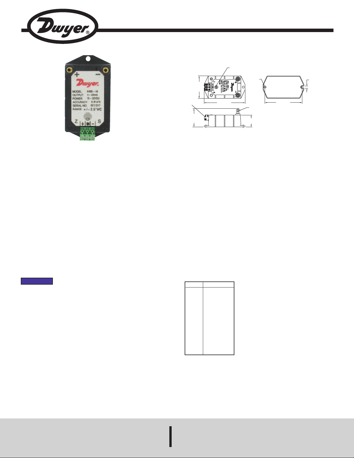
-57/64
[48.00]
T
ERMINAL
BLOCK
1-9/16
[39.50]
3-15/32
[88.00]
1
[25.40]
B
RASS
HOLE
B
ARBS
3
-5/32
[80.00]
Ø
3/16
[Ø4.80]
3
/16
[4.80]
LED
Series 648B Differential Pressure Transmitter
Specifications - Installation and Operating Instructions
he Series 648B Differential Pressure Transmitter is designed to be used with
T
clean, dry air and other non-corrosive gases. Each unit features a push-activated
zero function and an associated LED light indicator. With the convenient pushbutton, zero calibration can be performed without any additional equipment,
which significantly reduces time and cost for users. The dual color LED indicates
f the transmitter is at normal operation, overpressure, or in the process of zero
i
alibration. The enclosure consists of a flame retardant plastic top cover and a
c
tainless steel bottom plate for ruggedness. The pressure ranges vary from 0.1
s
in w.c. to 25 in w.c. unidirectional and 0.25 in w.c. to 5 in w.c. bidirectional. Wiring
time is reduced with the removeable terminal block. Each unit features a 2-wire
4 to 20 mA output that is fully protected against short circuiting and incorrect
wiring.
Mounting
Series 648B is designed for mounting by using the two (2) slots (suitable for #6
screws) that are provided on the mounting plate. For optimum performance, isolate
the instrument from vibration and provide relatively clean, dry air to the pressure
ports.
In most applications, preferred installation is with the baseplate mounted vertically
and located on a flat surface in a junction box or attached to a nearby beam. Quick
and easy field replacement is possible by removing the single case screw that
holds the housing to the baseplate and lifting the housing free. The baseplate will
remain mounted and can be used with the replacement units housing.
NOTICE
Piping
Two (2) 3/16˝ OD barbed pressure fittings are provided for pressure connection
with 1/8˝ ID push on tubing.
The overpressure limit with the new tension diaphragm construction is up to 15 psi
regardless of range.
The axis most sensitive to vibration is the one perpendicular to
the baseplate. Avoid mounting with maximum vibration along
axis.
SPECIFICATIONS
ervice: Air and non-combustible, compatible gases.
S
etted Materials: 302 SS, glass, nickel, silicon rubber, polyethylene, acrylic,
W
BS and brass.
A
Accuracy: ±0.8% FS* at room temperature.
*RSS (Root Sum Square) includes non-linearity, hysteresis and non-
repeatability.
Stability: ±1% FS/yr.
emperature Limits:
T
Operating: 0 to 170°F (-18 to 77°C);
Storage: -65 to 185°F (-54 to 85°C).
Pressure Limits:
15 psi (100 kPa) proof pressure;
30 psi (200 kPa) burst pressure.
Thermal Effects: ±0.025% FS/°F (0.045%/°C).
Power Requirements: 13 to 32 VDC.
Output Signal: 4 to 20 mA.
Zero and Span Adjustments: Push-button for zero, potentiometer for span.
Response Time: Approximately 10 ms.
Max. Loop Resistance: DC: 0 to 950 Ω.
Electrical Connection: Detachable euro-style terminal block.
Process Connections: 3/16˝ OD barbed fitting for 1/8˝ ID push-on tubing.
Housing: SS and PC+ABS alloy.
Weight: 3.8 oz (108 g).
Model
648B-1
648B-2
648B-3
648B-4
648B-5
648B-6
648B-7
648B-8
648B-13
648B-14
648B-15
648B-16
648B-17
Range in w.c.
0 to 0.1
0 to 0.25
0 to 0.5
0 to 1
0 to 2.5
0 to 5
0 to 10
0 to 25
0 to ±0.25
0 to ±0.5
0 to ±1
0 to ±2.5
0 to ±5
DWYER INSTRUMENTS, INC.
P.O. BOX 373 • MICHIGAN CITY, INDIANA 46361, U.S.A. Fax: 219/872-9057 e-mail: info@dwyer-inst.com
Phone: 219/879-8000 www.dwyer-inst.com
Page 2

Electrical
P
OWER
SUPPLY
13-32 VDC
P
RESSURE
T
RANSMITTER
RECEIVER
The Series 648B is a two (2) wire circuit (+SUPPLY, -RECEIVER) with a 4 to 20 mA
output. The unit is calibrated at the factory using a 250 ohm load at 24 VDC.
IRING DIAGRAM FOR 648B SERIES
W
alibration
C
The 648B series is factory calibrated and should require no field adjustment.
However, both zero and span adjustments are provided near the screw terminal strip.
Whenever possible, any zero and/or span offsets should be corrected by software
djustment in the user’s control system. Use the zero and span adjustments on the
a
48B series only if absolutely necessary. The 648B series is calibrated in the vertical
6
osition at the factory (baseplate vertical). For use in any other orientation, position
p
the unit and follow the adjustment procedure listed below. If a change in range is
needed, contact the Customer Service Department for a replacement in the
appropriate range.
ero Adjustment
Z
hile monitoring the current output with both pressure ports open to atmosphere, the
W
ero may be adjusted. Use push-button adjustment on the front of the unit to reset
z
zero.
Span Adjustment
Span or output adjustments should only done using an accurate pressure standard
electric manometer, digital pressure gage, etc.). With FS pressure applied to the high
(
ressure port (reference open to atmosphere), adjust span to achieve 20 mA output.
p
MAINTENANCE/REPAIR
Upon final installation of the Series 648B, no routine maintenance is required. The
Series 648B is not field serviceable and should be returned if repair is needed. Field
repair should not be attempted and may void warranty.
WARRANTY/RETURN
Refer to “Terms and Conditions of Sales” in our catalog and on our website. Contact
customer service to receive a Return Goods Authorization number before shipping the
product back for repair. Be sure to include a brief description of the problem plus any
additional application notes.
©Copyright 2011 Dwyer Instruments, Inc. Printed in U.S.A. 7/11 FR# R1-443886-00
DWYER INSTRUMENTS, INC.
P.O. BOX 373 • MICHIGAN CITY, INDIANA 46361, U.S.A. Fax: 219/872-9057 e-mail: info@dwyer-inst.com
Phone: 219/879-8000 www.dwyer-inst.com
 Loading...