

Dwyer Instruments 634ES Series, 634ES-0, 634ES-2, 634ES-3, 634ES-1 Specifications-installation And Operating Instructions
...Page 1
The Series 634ES Pressure Transmitter senses a single
air, compatible gas or liquid pressure and converts it into
a standard 4-20 mA output signal. Ranges are available
from 0-10 through 0-6000 psi. All models are field
adjustable so any range within these limits can be
achieved by recalibration using the easily accessible
span and zero potentiometers.
Positive pressure can be measured within an accuracy of
±0.5% of span. The Series 634ES uses an isolated
piezoresistive pressure sensor to produce a resistance
change across a wheatstone bridge. The signal is conditioned and converted into a 4-20 mA output signal.
For applications requiring direct pressure or percent of
full span readings, the optional A-701 digital readout
makes an ideal companion device, providing a bright .6”
high, 3-1/2˝ digit LED and supplying power to the Series
634ES Transmitter.
PHYSICAL DATA
GENERAL
Maximum Pressure: See chart on this page.
Wetted Parts: 316, 316L Stainless Steel.
Housing: Designed to meet NEMA-4X.
ELECTRICAL
Power Supply: 12.3-35 VDC-2 wire.
Output Signal: 4-20 mA DC (limited at 38 mA DC).
Loop Resistance: 0 - 1100 ohms from 12.3 to 35 VDC.
R
L max
=
Current Consumption: DC: 38 mA max.
MATERIALS
Housing: Cast aluminum; textured gray polyurethane
finish.
Pressure Connection: Stainless Steel.
MECHANICAL
Weight: 1 lb., 12 oz. (.8 kg).
Span and Zero Adjustments: Protected potentiome-
ters, located in auxiliary housing.
Pressure Connection: 1/4˝ female NPT x 1/2˝ male
NPT.
PERFORMANCE AT 70°F (21.1°C)
Zero Output: 4 mA DC.
Full Span: 16 mA DC.
Accuracy: ±0.5% of span.
Warm-up Time: 10 minutes.
STABILITY/ENVIRONMENTAL
Operating Temperature: 20 to 120˚F (- 6.7 to 48.9˚C).
Thermal Errors: ± 0.02%/˚F typical.
Stability: 1% F.S./yr.
STANDARD ACCESSORIES
(3) “Z” mounting brackets.
(3) 10-32 x 4” RH machine screws.
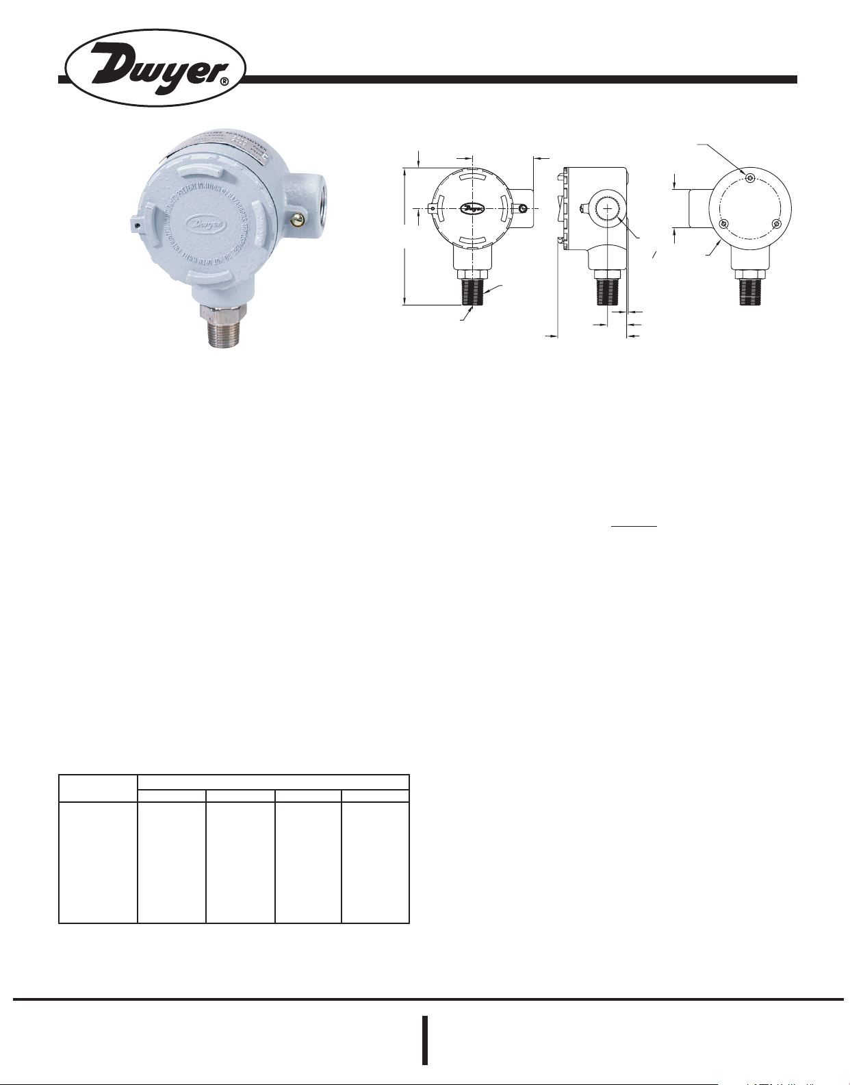
Series 634ES Pressure Transmitter
Specifications - Installation and Operating Instructions
Bulletin E-69ES
Vps-12.3V
20 mA
Series 634ES Models and Ranges in PSI (bar)
634ES-0
634ES-1
634ES-2
634ES-3
634ES-4
634ES-5
634ES-6
634ES-7
634ES-8
634ES-9
10 (.69)
30 (2.07)
50 (3.45)
100 (6.9)
200 (13.8)
300 (20.7)
500 (34.5)
1000 (69)
2000 (138)
4000 (276)
10 (.69)
20 (1.38)
40 (2.76)
60 (4.14)
100 (6.9)
250 (17.2)
350 (24.1)
600 (41.4)
1250 (86)
2500 (172)
20 (1.38)
40 (2.76)
60 (4.14)
120 (8.3)
250 (17.2)
350 (24.1)
600 (41.4)
1250 (86)
2500 (172)
6000 (414)
30 (2.07)
60 (4.14)
100 (6.9)
200 (13.8)
400 (27.6)
500 (34.5)
1000 (69)
2000 (138)
4000 (276)
7500 (517)
Model Number As Stocked Min. Range Max. Range Max Pressure
DWYER INSTRUMENTS, INC.
Phone: 219/879-8000 www.dwyer-inst.com
P.O. BOX 373 • MICHIGAN CITY, INDIANA 46361, U.S.A. Fax: 219/872-9057 e-mail: info@dwyer-inst.com
Lit-By Fax: 888/891-4963
(3) #10-32 x 1/4 [6.35] DP HOLES
EQUALLY SPACED ON A 2-1/2 [63.50] B.C.
TYP
1/2NPT
1-9/16
[39.69]
3/4 NPT
03-3/8 [85.73]
1-11/16
5-5/16
[134.94]
2-1/2 [63.50]
[42.86]
1/4NPT
2-7/8 [73.03]
1/16 [1.59]
25/32 [19.84]
Page 2
INSTALLATION
LOCATION: Select a location where temperature of the
unit will be between 20°F and 120°F. Distance from the
receiver is limited only by total loop resistance. See
“Electrical Connections.” The tube feeding the pressure
to the instrument can be run practically any length
required, but long lengths will slightly increase response
time. Avoid surfaces with excessive vibration.
POSITION: A vertical position is recommended, as all
stocked models are spanned and zeroed at the factory in
this position. They can be used at other angles, but final
spanning and zeroing must be done while transmitter is in
the alternative position.
PRESSURE CONNECTIONS: A single pressure connection is provided at the bottom of the transmitter housing.
It has1/4” female NPT and 1/2” male NPT threads. Attach
positive pressure to this port.
MOUNTING: The Series 634ES Transmitter can be
mounted three ways:
(A) Supported directly by pipe providing pressure.
(B) Attached to a mounting surface with 10-32 x 1/4”
machine screws (included). The machine screws are
installed through the mounting surface into tapped holes
on back of unit.
(C) Mounted with “Z” brackets (included). Attach “Z”
brackets to tapped holes on back of unit and fasten to
front of mounting surface.
ELECTRICAL CONNECTIONS
CAUTION: DO NOT EXCEED SPECIFIED SUPPLY VOLT-
AGE RATINGS. PERMANENT DAMAGE NOT COVERED
BY WARRANTY WILL RESULT. THIS UNIT IS NOT
DESIGNED FOR AC VOLTAGE OPERATION.
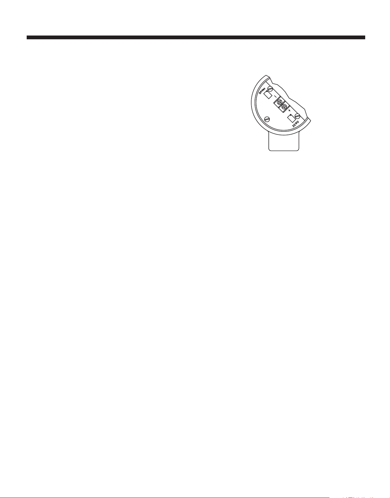
Electrical connections to the Series 634ES Transmitter
are made inside the enclosure. Remove the cover, feed
stripped and tinned leads through the conduit opening
and connect to terminal block screws marked + and -.
See Figure A for locations of terminal block, span and
zero adjust potentiometers. See Figure B (Pg. 3) for
schematic diagram.
FIG. A
An external power supply delivering 12.3 to 35 VDC with
minimum current capability of 40 mA must be used to
power the control loop in which the Series 634ES
Transmitter is connected. See Figure B for connection of
the power supply, transmitter and receiver.
The range of appropriate receiver load resistance (RL) for
the power supply voltage available is given by the formula and graph in Figure C on Pg. 3.
Shielded 2-wire cable is recommended for control loop
wiring, and the cable shielding may be grounded if
desired. Note also that the receiver may be connected in
either the negative or positive side of the loop, whichever
is most convenient.
Should polarity of the transmitter or receiver inadvertently become reversed, the loop will not function properly,
but no damage will be done to the transmitter.
Series 634ES Pressure Transmitter
Specifications - Installation and Operating Instructions
Bulletin E-69ES
Page 2
Page 3

FIG. B
Series 634ES Transmitters can be used with receivers
requiring 1-5 volt input rather than 4-20 mA. If the receiver
requires a 1-5 volt input, insert a 250 ohm, 2 watt resistor
in series with the current loop but in parallel with the
receiver input. Referring to Figure B, RL becomes the 250
ohm resistor and points X and Y are connected to the
receiver input, point X being positive (+) and point Y negative (-) or ground. The resistor should be connected at
the panel end of the transmitter current loop close to the
receiver input to take advantage of the immunity of the
current loop to electrical noise pickup. Most electronic
component distributors stock a 249 Ω, 2 watt, ± 1% tolerance metal film resistor which is adequate for this application.
Series 634ES Pressure Transmitter
Specifications - Installation and Operating Instructions
Bulletin E-69ES
Page 3
WIRE LENGTH - The maximum length of wire connecting transmitter and receiver is a function of wire size and
receiver resistance. Wiring should not contribute more
than 10% of receiver resistance to total loop resistance.
For extremely long runs (over 1000 feet) choose receivers
with higher resistances to minimize size and costs of
connecting leads. When wiring length is under 100 feet,
lead wire as small as 22 AWG can be used.
PRESSURE RANGING - Each Series 634ES Transmitter
is factory-calibrated to the range given in the model number chart. However, special calibration is also available.
If this is the case, the transmitter will be so marked. For
purposes of clarification in these instructions, range is
defined as that pressure which, applied to the transmitter,
produces 20 mA of current in the loop. Zero pressure is
always assumed to be 4 mA. If a transmitter pressure
range other than that supplied is required, follow the reranging procedure described on Pg. 4.
FIG. C
634ES
PRESSURE
TRANSMITTER
RECEIVER
SEE FIG. C
POWER
SUPPLY
12-35 VDC
TOTAL RECEIVER RESISTANCE
MAXIMUM VALUE (1100 )
Vps-12.3
20mA DC
OPERATING
REGION
Page 4

PRESSURE RE-RANGING PROCEDURE
1. With the transmitter correctly connected to the com-
panion receiver, an accurate milliameter with a full scale
reading of approximately 30 mA should be inserted in
series with the current loop. A controllable pressure
source capable of achieving the desired range should be
connected to the pressure port of the transmitter and teed
into an accurate reference pressure gauge or manometer.
The instrument must be ranged in the same position in
which it will be used. Vertical mounting is recommended.
2. Apply electrical power to the system and allow it to
stabilize for 10 minutes.
3. With no pressure applied to the transmitter, adjust
“zero” control so that loop current is 4 mA.
4. Apply full range pressure and adjust loop current to 20
mA using “span” control.
5. Relieve pressure and allow transmitter to stabilize for
two minutes.
6. Zero and span adjustments may be interactive, so
repeat steps 3 through 5 until zero and full range pressures consistently produce loop currents of 4 and 20 mA
respectively.
7. Remove the milliameter from the current loop and proceed with final installation of the transmitter and receiver.
MULTIPLE RECEIVER INSTALLATION
An advantage of the standard 4-20 mA output signal provided by the Series 634ES Pressure Transmitter is that
any number of receivers can be connected in series in the
current loop. Thus, an A-701 Digital Readout Accessory,
an analog panel meter, a chart recorder, process controlling equipment, or any combination of these devices can
be operated simultaneously. It is only necessary that
these devices all be equipped with a standard 4-20 mA
input and that proper polarity of the input connections be
observed when inserting the device in the current loop. If
any of the receiving devices displays a negative or downscale reading, this indicates that the signal input leads are
reversed.
MAINTENANCE
Upon final installation of the Series 634ES Transmitter and
the companion receiver, including the A-701 Digital
Readout, no routine maintenance is required. A periodic
check of system calibration is recommended. The Series
634ES Pressure Transmitter is not field serviceable and
should be returned, freight prepaid, to the factory if repair
is required. The A-701 Digital Readout should be
returned to the manufacturer if service is needed. Refer
to the A-701 instruction sheet.
©Copyright 2002 Dwyer Instruments, Inc. Printed in U.S.A. 6/02 FR# 01-440577-04, Rev. 3
Series 634ES Pressure Transmitter
Specifications - Installation and Operating Instructions
Bulletin E-69ES
Page 4
DWYER INSTRUMENTS, INC.
Phone: 219/879-8000 www.dwyer-inst.com
P.O. BOX 373 • MICHIGAN CITY, INDIANA 46361, U.S.A. Fax: 219/872-9057 e-mail: info@dwyer-inst.com
Lit-By Fax: 888/891-4963
 Loading...