

Page 1
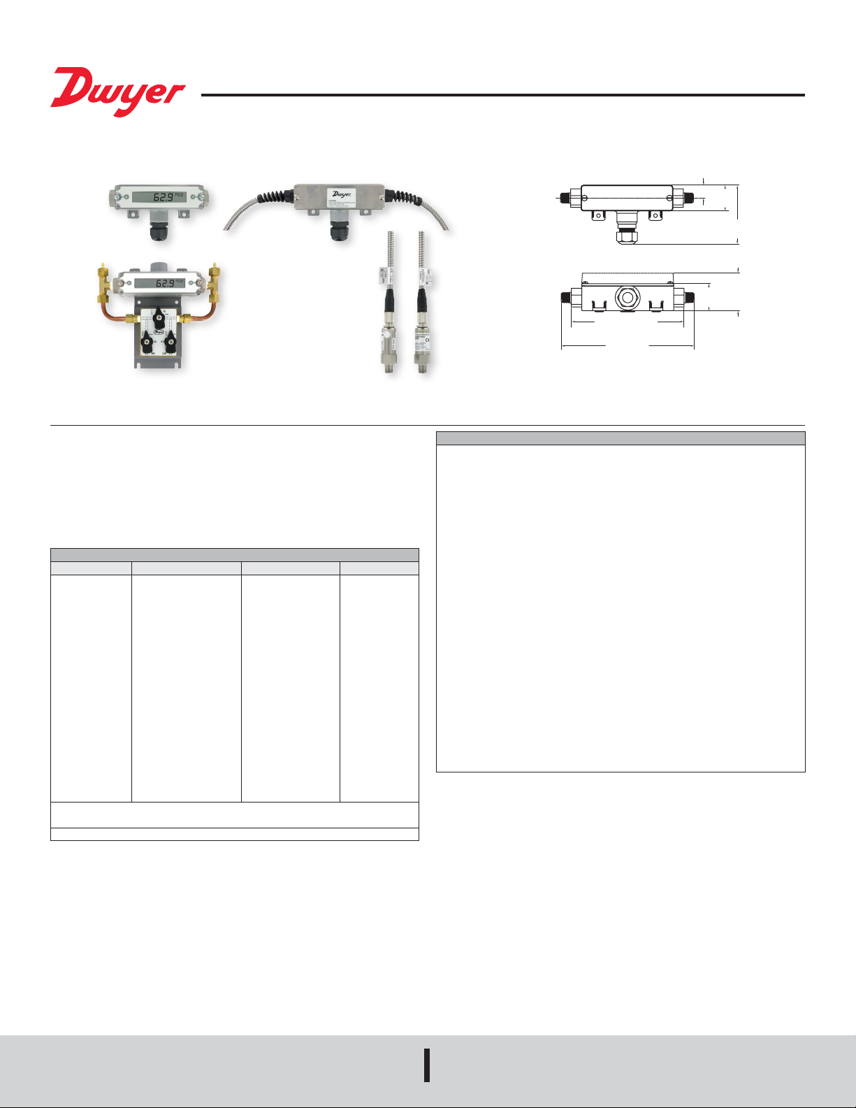
Series 629C Wet/Wet Differential Pressure Transmitter
D
OPTIONAL 1/4 NPT MALE FITTING
1-27/64
[35.98]
1-31/32 [50.16]
OPTIONAL LCD
5-15/16 [150.88]
1/4 NPT FEMALE FITTING
7 [177.80]
®
Specications - Installation and Operating Instructions
Conduit housing
with remote sensor
available in
10´ or 20´ shielded
629C-RS
Option
or armored cable
5-15/16 [150.88]
1/4 NPT FEMALE FITTING
7 [177.80]
Bulletin P-629C
43/64
[17.15]
1-11/32
[34.29]
3-7/64
[78.83]
1-27/64
[35.98]
1-31/32 [50.16]
OPTIONAL LC
The Series 629C Wet/Wet Differential Pressure Transmitter monitors differential
pressure of compatible gases and liquids with 0.5% accuracy. The design employs
dual pressure sensors converting pressure changes into a 4 to 20 mA or voltage output
signal. Small internal volume and minimal moving parts result in exceptional response
and reliability. The wiring terminals and zero adjustment button are easily accessed
under the removable cover. The Series 629C is designed to meet NEMA 4X (IP66)
weatherproof construction.
RANGE
Range Number Range Working Pressure* Over Pressure
01
02
03
04
05
06
07
08
09
11
12
13
14
15
16
17
18
19
*Pressures exceeding the working pressure limit may cause a calibration shift of up
to ±3% of full scale.
Note: Over pressure of all models with 3-way valve is 100 psi.
0 to 5 psid
0 to 10 psid
0 to 25 psid
0 to 50 psid
0 to 100 psid
0 to 150 psid
0 to 200 psid
0 to 300 psid
0 to 500 psid
0 to 0.5 bar differential
0 to 1 bar differential
0 to 2 bar differential
0 to 4 bar differential
0 to 6 bar differential
0 to 10 bar differential
0 to 15 bar differential
0 to 20 bar differential
0 to 30 bar differential
Table 1: Pressure Limits
10 psi
20 psi
50 psi
100 psi
200 psi
300 psi
400 psi
600 psi
1000 psi
1 bar
2 bar
4 bar
8 bar
12 bar
20 bar
30 bar
40 bar
60 bar
50 psi
50 psi
120 psi
250 psi
500 psi
750 psi
1000 psi
1200 psi
2000 psi
3 bar
8 bar
8 bar
18 bar
18 bar
50 bar
60 bar
80 bar
120 bar
SPECIFICATIONS
Service: Compatible gases and liquids.
Wetted Materials: Without valve: 316, 316L SS. Additional wetted parts with
valve option: Buna-N, silicone grease, PTFE, brass 360, copper, and reinforced
copolymer.
Accuracy: ±0.5% FS (includes linearity, hysteresis & repeatability).
Stability: ±1% FS/year.
Temperature Limits: 0 to 200°F (-18 to 93°C).
Compensated Temperature Limits: 0 to 175°F (-18 to 79°C).
Pressure Limits: See Table 1.
Thermal Effects: Avg 0.04%/°F (0.072%/°C) (includes zero and span).
Power Requirements: 2-wire: 10 to 35 VDC; 3-wire: 13 to 35 VDC or isolated 16 to
33 VAC (reverse polarity protected).
Output Signal: 2-wire: 4 to 20 mA; 3-wire: Field selectable 0 to 5, 1 to 5, 0 to 10, or
2 to 10 VDC.
Zero and Units: Push buttons inside conduit enclosure.
Response Time: 400 msec.
Loop Resistance: Current output: 0 to 1250 Ω (max), Rmax = 50(Vps-10); Voltage
output: Minimum load resistance = 5 kΩ.
Current Consumption: 28 mA (max).
Electrical Connections: Removable terminal block; 1/2˝ female NPT conduit.
Process Connections: 1/4˝ female or male NPT.
Display: Optional 4-1/2 digit LCD eld attachable display.
Enclosure Rating: Designed to meet NEMA 4X (IP66) for non-LCD models.
Mounting Orientation: Not position sensitive.
Weight: 10.1 oz (286 g).
Agency Approvals: CE.
DWYER INSTRUMENTS, INC.
P.O. BOX 373 • MICHIGAN CITY, INDIANA 46360, U.S.A.
Phone: 219/879-8000
Fax: 219/872-9057
www.dwyer-inst.com
e-mail: info@dwyermail.com
Page 2
MODEL CHART
7-17/64 [184.66]
[142.11]
[108.33]
3 [76.19]
Example 629C -01 -CH -P1 -E1 -S1 -3V 629C-01-CH-P1-E1-S1-3V
Series 629C Wet/wet differential pressure transmitter
Range 01
Housing CH
Process
Connection
Electrical
Connection
Signal Output S1
Options 3V
*Pressures exceeding the working pressure limit may cause a calibration shift of up to ±3% of full scale.
02
03
04
05
06
07
08
09
11
12
13
14
15
16
17
18
19
R1
R2
R5
R6
P1
P2
P3
P4
E1
E2
E3
E5
E9
S3
0 to 5 psid
0 to 10 psid
0 to 25 psid
0 to 50 psid
0 to 100 psid
0 to 150 psid
0 to 200 psid
0 to 300 psid
0 to 500 psid
0 to 0.5 bar differential
0 to 1 bar differential
0 to 2 bar differential
0 to 4 bar differential
0 to 6 bar differential
0 to 10 bar differential
0 to 15 bar differential
0 to 20 bar differential
0 to 30 bar differential
Conduit housing, NEMA 4X (IP66)
Conduit housing, NEMA 4X (IP66), with remote sensor and 10´ shielded cable
Conduit housing, NEMA 4X (IP66), with remote sensor and 20´ shielded cable
Conduit housing, NEMA 4X (IP66), with remote sensor and 10´ armored cable
Conduit housing, NEMA 4X (IP66), with remote sensor and 20´ armored cable
1/4˝ male NPT
1/4˝ female NPT
1/4˝ male BSPT
1/4˝ female BSPT
Cable gland with 3´ of prewired cable
Cable gland with 6´ of prewired cable
Cable gland with 9´ of prewired cable
1/2˝ female NPT conduit
M-12 4 pin connector (not UL)
4 to 20 mA
Field selectable 0 to 5, 1 to 5, 0 to 10, 2 to 10 VDC
3-way valve
AT
Aluminum tag
FC
Factory calibration certicate
LCD
LCD indication
NIST
NIST traceable certicate
INSTALLATION
1. Location: Select a location where the temperature of the unit will be between
0 and 200°F (-18 to 93°C). Distance from the receiver is limited only by total loop
resistance (see electrical connections). The tubing feeding pressure to the instrument
can be practically any length required, but long lengths will increase the response
time slightly. Mount the instrument in a location that will not be subject to excessive
temperature, shock, or vibration.
2. Position: A vertical position is recommended (pressure connections pointing
horizontally) since that is how all standard models are spanned and zeroed at the
factory. They can be used at other angles, but may require nal zeroing. Due to
potential condensation buildup that may travel down conduit or cable and into the
housing, it is recommended to install with the electrical conduit or cable gland pointing
downward.
3. Pressure Connection: Dual 1/4˝ NPT pressure connections are provided. Use pipe
thread sealant tape or other suitable pipe joint compound when making connection to
the pressure source. Avoid excess sealant which could block the pressure passage.
When monitoring liquid pressures, air trapped in the lines can cause incorrect readings.
Bleed ttings or similar mechanisms should be used to bleed off any trapped air.
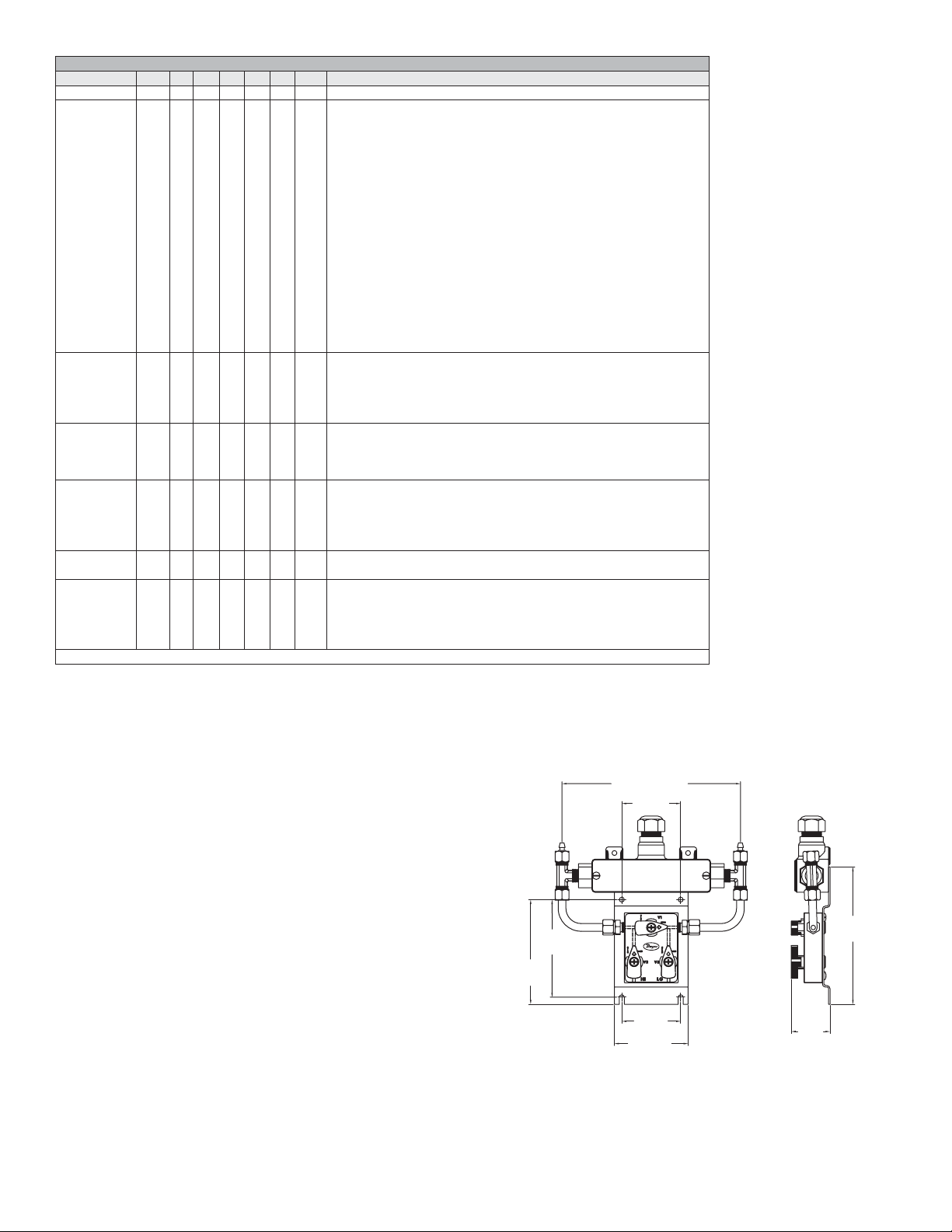
Optional 3-Way Valve
For applications where higher line pressures may be encountered at installation or
when it is necessary to remove the transmitter for maintenance without interrupting the
process, the optional three way valve is recommended. (See Figure 1)
2-13/32
[60.96]
1-37/64
[40.14]
5-19/32
[101.02]
4-17/64
3-63/64
2-25/64
[60.84]
Figure 1: 629C with Optional 3-Way Valve
Page 3
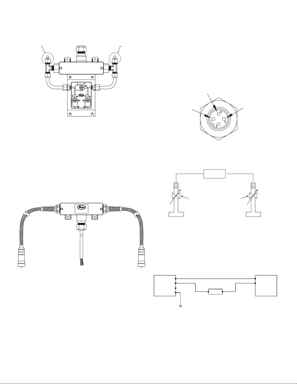
Installation with 3-way valve option. Begin with valve V1 open and valves V2 and
VIN
+
BLEED FITTING
BLEED FITTING
PRESSURE
PRESSURE
PIPE
TERMINAL 4: (-)
TERMINAL
3:
V3 closed. (See Figure 2) Slowly open valves V2 and V3. Once the pressure has
stabilized and is equal on the high and low side of the transmitter, valve V1 can be
closed and normal operation can proceed.
HIGH SIDE
LOW SIDE
Install the high and low remote sensors in respective locations in the process. Use
of thread sealant is recommended to prevent leaks. During installation, care must be
taken to ensure that the serial number on the sensor matches the serial number on
the transmitter housing. Additionally, a check must be made to ensure that the check
box for high or low pressure on the sensor matches the check box for high or low
pressure on the cable tag. The sensor with a mark in the “High Pressure” box should
be connected to the higher pressure, and the sensor with a mark in the “Low Pressure”
box should be connected to the lower pressure in order to ensure accurate readings.
The vent hole on the side of the unit should not be covered by anything aside from
the ber lter installed from the factory. Do not remove the ber lter installed over the
vent hole.
After sensor installation, attach the cable to the sensor by means of the M-12 connector
shown in Figure 4. The cables connecting the sensors to the transmitter housing can
only be disconnected at the sensor by means of the M-12 connectors. No attempt
should be made to disconnect remote cables at the transmitter housing.
Figure 2: Bleed Fitting Connections
To ensure proper pressures will be detected by the 629C, use the bleed ttings
provided with this package to free media of bubbles. Before applying pressure to the
process connections, turn V1 to the open position and back off either the low or high
side bleed hex nut. Next, apply pressure. After the owing liquid is free of bubbles,
retighten the bleed hex nut.
Before removing the transmitter from operation, open valve V1, then close valves V2
and V3.
Optional Remote Sensor Installation
For both shielded cable and armored cable versions of remote sensors option, follow
standard installation procedures.
CAUTION:
ALWAYS USE WRENCH ON PRESSURE BLOCK
WHEN TIGHTENING FITTING.
NEVER PUT STRESS ON HOUSING.
1: (+)
TERMINAL
(GROUND)
Figure 4: M-12 Connector
For applications where differential pressure is measured at high line pressure, it is
recommended to install pressure sensor with a valve in each line and a shunt valve
across the high and low pressure ports (see Figure 5).
629C-RS
HIGH
REMOTE
SENSOR
SHUNT
VALV E
SHUNT
VALV E
LOW
REMOTE
SENSOR
Figure 5: Sensor Installation with Valves
ELECTRICAL CONNECTIONS
Shielded cable is recommended for control loop wiring. Electrical connections to the
Series 629C pressure transmitters are made to the terminal block located inside the
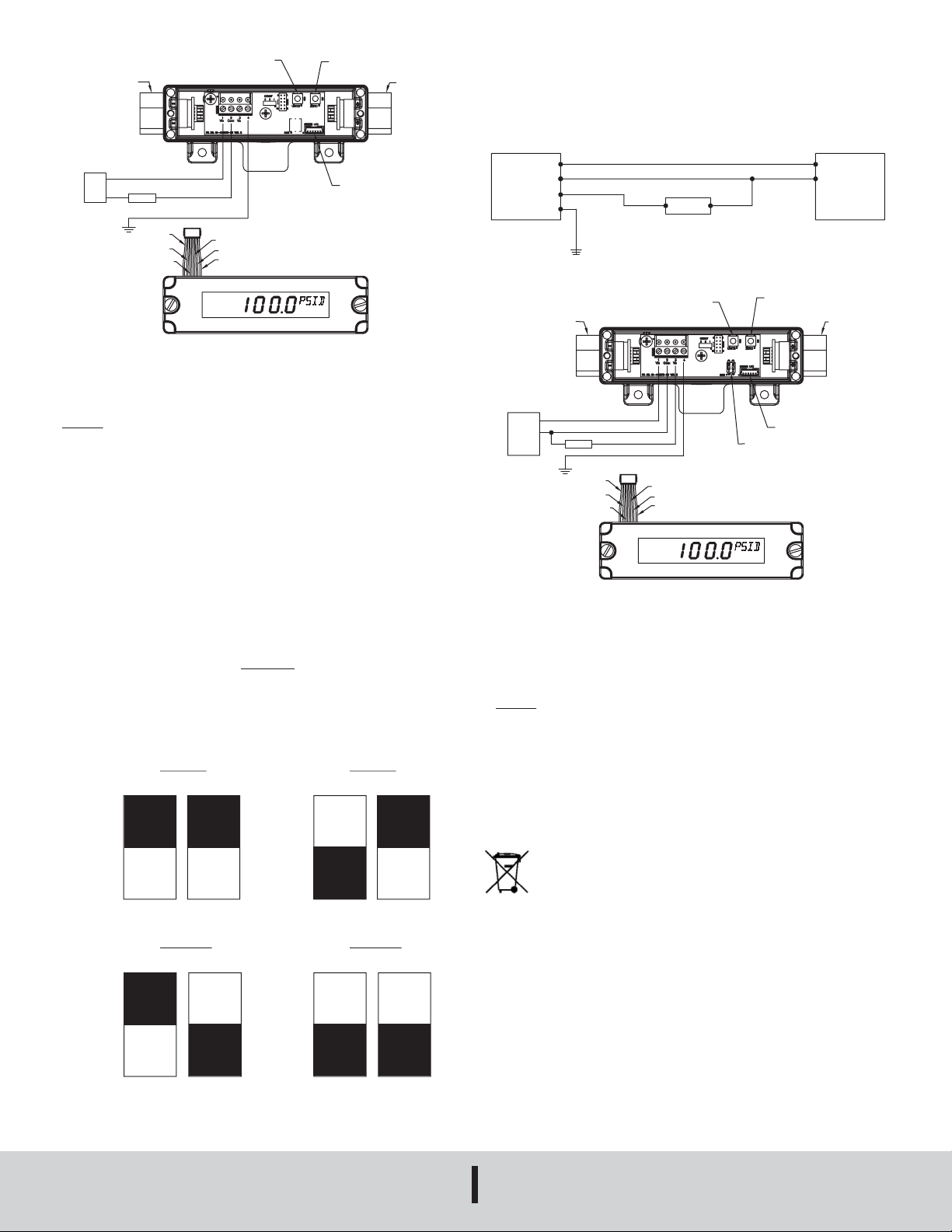
housing. Remove the screws and lift off the cover. Wire as shown in Figure 6 or 7. Use
Figure 6 for current output connection. Use Figure 7 for current output with optional
LCD display. If ordering pre-wired cable, black wire is negative (-) and red wire is
positive (+).
Figure 3: 629C with Remote Sensor
PRESSURE
TRANSMITTER
1
COM
2
3
4
+-
RECEIVER
SHIELD
Figure 6: Current Output Connection
-
POWER
SUPPLY
10-35 VDC
Page 4
1
VIN
+
LCD CONNECTOR. FAILURE TO DO SO CAN RESULT IN GAGE DAMAGE.
CONNECTION
UNIT BUTTON-PRESS TO TOGGLE THE
ZERO BUTTON-PRESS AND
OR ISOLA
CONNECTION
LOW [-]
UNIT BUTTON-PRESS TO TOGGLE THE
ZERO BUTTON- PRESS AND
TRANSMITTER CONNECTION INSTRUCTION:
- TURN OFF POWER SUPP
- CONNECT THE POWER SUPPL
[TERM #2] OF THE GAGE AS SHOWN
- INST
- TURN ON POWER
CAUTION: BE SURE TO TURN OFF POWER WHEN CONNECTING OR REMOVING
THE LCD CONNECTOR. FAILURE TO DO SO CAN RESULT IN GAGE DAMAGE.
PRESSURE
CONNECTION
POWER
SUPPLY
10-35 VDC
+
-
UNIT [PSID/BARD] ON THE LCD
Vin [TERM #1]
Com [TERM #2]
+
-
RECEIVER
SHIELD [TERM #4]
RED
BLACK
BLUE
ORANGE
YELLOW
WHITE
HOLD TO ZERO THE GAGE
LCD CONNECTOR
HI [+]
PRESSURE
For voltage outputs, wire as shown in Figure 9 for voltage output connection. Use
Figure 10 for voltage output with optional LCD display. Terminal 1 is positive (+),
terminal 2 is negative (-), and terminal 3 is +Vout. If ordering optional prewired cable,
black wire is negative (-), red wire is positive (+), and white wire is +Vout. For optimal
accuracy, use a separate common wire for the receiver.
PRESSURE
TRANSMITTER
COM
2
VO
3
4
SHIELD
Figure 9: Voltage Output Connection
+-
RECEIVER
POWER
SUPPLY
13-35 VDC
OR 16-33 VAC
LY.
Y AND RECEIEVER TO Vin [TERM #1] AND Com
L max =
R
.
vps - 10
20 mA DC
ON
OFF
1 to 5 VDC
1 2
1 2
ALL THE LCD'S CONNECTOR TO THE GAGE AS SHOWN.
Wire Length – The maximum length of wire connecting transmitter and receiver is
a function of wire size and receiver resistance. Wiring should not contribute to more
than 10% of receiver resistance to total loop resistance. For extremely long runs (over
1000 ft or 305 m), choose receivers with higher resistance to minimize size and cost
of connecting leads. When wiring length is under 100 ft (30.5 m), lead wire as small
as 22 AWG can be used.
Current (4 to 20 mA) Output Operation – An external power supply delivering 10 to
35 VDC with minimum current capability of 40 mA DC (per transmitter) is required to
power the control loop. See Figure 9 for connection of the power supply, transmitter,
and receiver. The range of the appropriate receiver load resistance (RL) for the DC
power supply voltage available is expressed by the formula
VOLTAGE (0 TO 5, 1 TO 5, 0 TO 10, OR 2 TO 10 V) OUTPUT OPERATION
To select the voltage output that is going to be used, congure the dip switches
according to the Figure 8 below. Power must be cycled whenever dip switches are
changed to select output.
OFF
.
Figure 7: Current Output with Optional LCD
0 to 5 VDC
1 2
ON
0 to 10 VDC 2 to 10 VDC
1 2
UNIT [PSID/BARD] ON THE LCD
LOW [-]
PRESSURE
CONNECTION
+
-
POWER
SUPPLY
13-35 VDC
TED
16-33 VAC
TRANSMITTER CONNECTION INSTRUCTION:
- TURN OFF POWER SUPPLY.
- CONNECT THE POWER SUPPLY [+] TO Vin [TERM #1] AND [-] TO Com [TERM #2] OF
THE GAGE AS SHOWN.
- CONNECT THE RECEIVER [+] TO Vo [TERM #3] OF THE GAGE AND RECEIVER [-] TO
POWER SUPPLY [-].
- INSTALL THE LCD'S CONNECTOR TO THE GAGE AS SHOWN.
- SET VOLTAGE SELECTION DIP SWITCH TO DESIRED VOLTAGE OUTPUT.
- TURN ON POWER.
CAUTION: BE SURE TO TURN OFF POWER WHEN CONNECTING OR REMOVING THE
MAINTENANCE/REPAIR
Upon nal installation of the Series 629C Wet/Wet Differential Pressure Transmitter,
no routine maintenance is required. The Series 629C is not eld serviceable and is not
possible to repair the unit. Field repair should not be attempted and may void warranty.
This symbol indicates waste electrical products should not be disposed
of with household waste. Please recycle where facilities exist. Check with
your Local Authority or retailer for recycling advice.
WARRANTY/RETURN
Refer to “Terms and Conditions of Sale” in our catalog and on our website. Contact
customer service to receive a Return Material Authorization number before shipping
the product back for repair. Be sure to include a brief description of the problem plus
any additional application notes.
Vin [TERM #1]
Com [TERM #2]
Vo [TERM #3]
+
RECEIVER
SHILED [TERM #4]
RED
BLACK
BLUE
Figure 10: Voltage Output with Optional LCD Display
ORANGE
YELLOW
WHITE
HOLD TO ZERO THE GAG
LCD CONNECTOR
VOLTAGE SELECTION
DIP SWITCH
HI [+]
PRESSURE
ON
OFF
Figure 8: Voltage Output Dip Switch Selection
©Copyright 2019 Dwyer Instruments, Inc. Printed in U.S.A. 2/19 FR# 443277-10 Rev. 6
DWYER INSTRUMENTS, INC.
P.O. BOX 373 • MICHIGAN CITY, INDIANA 46360, U.S.A.
ON
OFF
Phone: 219/879-8000
Fax: 219/872-9057
www.dwyer-inst.com
e-mail: info@dwyermail.com
 Loading...