

Dwyer Instruments 604D-0, 604D Series, 604D-2, 604D-1, 604D-5 Specifications-installation And Operating Instructions
...Page 1

Series 604D Indicating Pressure Transmitter
Specifications - Installation and Operating Instructions
Bulletin E-34
The Dwyer Series 604D Indicating Transmitter simulta-
neously provides local indication on a compact, easy to
read analog scale while also converting that pressure into a
standard 2, 3 or 4 wire, 4-20 mA signal for ranges as low
as 0-0.5 in. w.c. Positive, negative or differential pressures
can be measured within ±5% of full scale (gage reading) or
±2% of full span output (transmitter signal). The basic
mechanical components of the Series 604D units are simi-
®
lar to those used in the popular, time-proven Minihelic
differential pressure gage. However, the Series 604D models
add electrical conditioning and amplification of a resistance
change produced by a silicon strain gage cemented to the
range spring. This resistance change is the result of a slight
flexing which results from spring deflection as pressure is
applied to the diaphragm which is mechanically linked to
the spring.
Series 604D Indicating Transmitter Model & Ranges
Model
Number
604D-0
604D-1
604D-2
604D-3
604D-5
604D-10
604D-20
604D-40
604D-60
604D-100
Ranges, Inches W.C.
0-0.5
0-1.0
0-2.0
0-3.0
0-5.0
0-10
0-20
0-40
0-60
0-100
Minor Divisions
.02
.05
.10
.10
.20
.50
1.0
2.0
2.0
5.0
PHYSICAL DATA
GENERAL
Maximum Pressure: 30 psig (207 kPa) continuous
50 psig (344 kPa) momentary surge.
Media Compatibility: Air and non-combustible, non-corrosive gases.
Materials: Mineral and glass filled nylon housing, high
impact acrylic cover, silicone rubber diaphragm.
ELECTRICAL
Power Supply: 10-35 VDC-2,3 or 4 wire
16-26 VAC-4 wire.
Connections: 4 screw terminal block
Cable Gland: Fits .10 - .25 in (2.5 - 6 mm) O.D. cable.
Output Signal: 4-20 mA DC (limited at 38 mA DC).
Loop Resistance: DC; 0-1300 ohms
AC; 0-1200 ohms.
Current Consumption: DC; 38 mA max. AC; 76 mA
max.
Warm-Up: 10 minutes.
PERFORMANCE AT 70°F (21.1°C)
Zero Output: 4 mA DC.
Full Span Output: 20 mA DC.
Accuracy, Gage: ±5% of full scale.
Accuracy, Transmitter: ±2% of full span output
(Includes linearity, hysteresis and repeatability).
Stability: 1% F.S./year.
ENVIRONMENTAL
Operating Temperature: 20-120°F (-6.7° to 49°C)
Thermal Errors: ±1%/50°F
MECHANICAL
Weight: 8 oz. (227 grams)
Span and Zero: Internally accessible potentiometers
Pressure Connections: Barbed, for 3/16″ (4-5 mm) I.D.
tubing.
STANDARD ACCESSORIES
(2) #10 x 1″ pan head sheet metal screws, (1) .050″ hex
allen wrench.
DWYER INSTRUMENTS, INC.
Phone: 219/879-8000 www.dwyer-inst.com
P.O. BOX 373 • MICHIGAN CITY, INDIANA 46361, U.S.A. Fax: 219/872-9057 e-mail: info@dwyer-inst.com
Lit-By Fax: 888/891-4963
Page 2
Series 604D Indicating Pressure Transmitter
Specifications - Installation and Operating Instructions
Bulletin E-34
Page 2
INSTALLATION
LOCATION: Select a location where temperature of the unit will be
between 20°F and 120°F (7°C and 49°C). Distance from the
receiver is limited only by total loop resistance. See “Electrical
Connections.” The tubing feeding pressure to the instrument can
be run practically any length required, but long lengths will slightly
increase response time. Avoid surfaces with excessive vibration.
POSITION: All models are calibrated with the scale in a vertical
plane and units with ranges under 5 in. w.c. should only be used
in that position due to the sensitivity to gravitational forces which
cannot be corrected by zero adjustment. Higher range models can
operate in other planes but zero (both mechanical electrical) and
span adjustments may be necessary to maintain accuracy.
PRESSURE CONNECTIONS: Two barbed connectors are provided for use with 3/16″ I.D. vinyl or rubber tubing. Attach tubing
from positive pressure source to HI port. Leave LO port vented.
For negative (vacuum) pressure, connect to LO port and leave HI
port vented. For differential pressures, connect the higher to HI
port and lower to LO port.
MOUNTING: Attach the Series 604D Indicating Transmitter to a
vertical surface using the 1″ - #10 pan head sheet metal screws
provided. Mounting holes are located in upper left and lower right
corners of case.
GAGE ZEROING:
After installation, check to confirm that gage reads exactly zero
with both pressure connections open and vented to atmosphere.
If adjustment is necessary, grip case firmly with one hand and
place palm of the other hand flat on clear cover. If difficult to grip,
try placing a thin sheet of rubber between hand and cover. Rotate
counter-clockwise to remove. Zero adjust screw is located at bottom of scale just to left of the indicating pointer and slightly behind
it. Use the .050″ hex allen wrench included. Replace cover.
ELECTRICAL CONNECTIONS
CAUTION: DO NOT EXCEED SPECIFIED SUPPLY VOLTAGE
RATINGS. PERMANENT DAMAGE NOT COVERED BY W ARRANTY WILL RESULT. THIS UNIT IS NOT DESIGNED FOR
120 VAC or 240 VAC LINE OPERATION.
Electrical connections to the Series 604D Indicating Transmitter
are made inside the enclosure on the left side of the unit. Remove
the cover and feed 4 conductor cable through the cable gland at
bottom of housing. Make electrical connections to the 4-screw terminal block shown in Fig. B. See following instructions and drawings for details on your specific application. When connections are
complete, tighten cable gland and replace cover.
Wire Length - The maximum length of wire connecting transmit-
ter and receiver is a function of wire size and receiver resistance.
Wiring should not contribute more than 10% of receiver resistance
to total loop resistance. For extremely long runs (over 1000 ft. [305
m]), choose receivers with higher resistances to minimize size and
cost of connecting leads. Where wiring length is under 100 ft.
(30.48 m), lead wire as small as 22 AWG can be used.
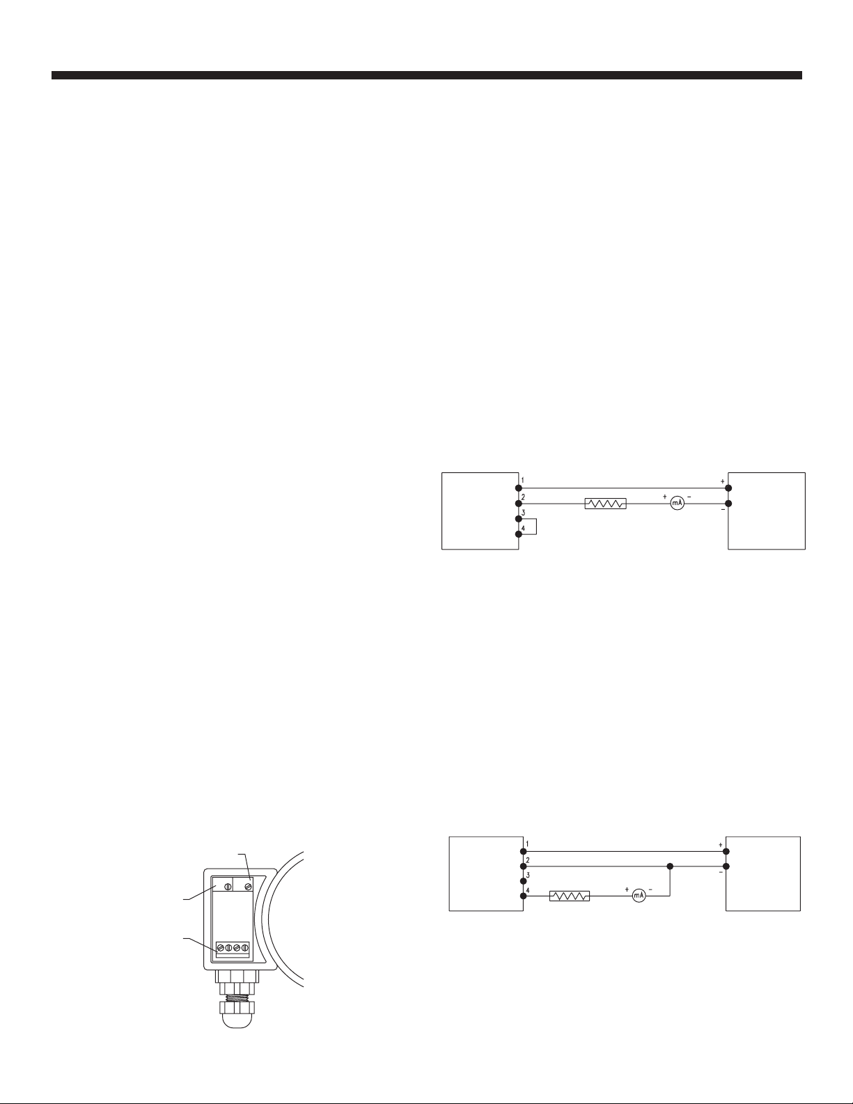
2-Wire Operation - An external power supply delivering 10-35
VDC with minimum current capability of 40 mA DC (per transmitter) must be used to power the control loop. See Fig. C for connection of the power supply, transmitter and receiver. Note the
jumper between terminals 3 and 4. The range of appropriate
receiver load resistance (R
L
) for the DC power supply voltage available is expressed by the formula and graph in Fig. F. Shielded two
wire cable is recommended for control loop wiring. If grounding is
required use negative side of control loop after receiver. In Fig.C
below, if power supply lead to terminal 1 is positive, ground should
be connected to wiring at right of receiver. Otherwise, in 2 wire
operation it is not necessary to observe polarity of control loop
connections.
2-WIRE CONNECTION
SERIES 604D
PRESSURE
TRANSMITTER
JUMPER
WIRE
RECEIVER
POWER
SUPPLY
10-35 VDC
Fig. C
3-Wire Operation - An external power supply delivering 10-35
VDC with minimum current capability of 40 mA DC (per transmitter) is required. See Fig. D for connection of power supply, transmitter and receiver. The range of appropriate receiver load resistance (R
L
) for the DC power supply available is expressed by the
formula and graph in Fig. F. Shielded cable is recommended for
control loop wiring. Do not employ a separate ground in 3 wire
operation. Unit will not function properly and/or damage could
result. Control loop polarity must be observed in the following
respect. Although power supply terminals 1 and 2 are not polarized, the receiver must be connected between terminal 4 of
transmitter and negative side of power supply.
3-WIRE CONNECTION
ZERO ADJUSTMENT
SPAN ADJUSTMENT
TERMINAL BLOCK
1234
Fig. B
SERIES 604D
PRESSURE
TRANSMITTER
RECEIVER
Fig. D
POWER
SUPPLY
10-35 VDC
Page 3

Series 604D Indicating Pressure Transmitter
Specifications - Installation and Operating Instructions
Bulletin E-34
Page 3
4-Wire Operation - An external power supply delivering
10-35 VDC with minimum current capability of 40 mA DC
(per transmitter) or 16-26 VAC with minimum current capability of 80 mA AC (per transmitter) is required. See Fig. E for
connection of power supply, transmitter and receiver. The
range of appropriate load resistance (RL) for the DC or AC
power supply available is expressed by the formulas and
graphs in Figs. F and G. Shielded cable is recommended for
control loop wiring. Do not employ a separate ground in 4
wire operation. Unit will not function properly and /or damage could result. Control loop polarity must be observed,
terminal 3 is negative and terminal 4 is positive. Power supply terminals 1 and 2 are not polarized.
4 WIRE CONNECTION
SERIES 604D
PRESSURE
TRANSMITTER
POWER
SUPPLY
10-35 VDC
16-26 VA C
Fig. E
POWER SUPPLY VOLTAGE-VDC (2, 3, OR 4 wire)
1500
1400
Ω)
1300
1200
1100
1000
900
800
700
600
500
400
300
200
TOTAL RECEIVER RESISTANCE (
100
50
RL MAX. = Vps-10.0
05
MAXIMUM VALUE (1300Ω)
20 mA DC
OPERATING
REGION
10 13 15 20 25 30 35 40
VDC
Fig. F
Voltage Input - Series 604D Indicating Pressure
Transmitters can be easily adapted for receivers requiring
1-5 VDC or 2-10 VDC input. Insert a 249 OHM, 1/2watt
(1-5 VDC) or 499 ohm (2-10 VDC) resistor in series with the
current loop but in parallel with the receiver input. Locate
this resistor as close as possible to the input. Because
resistor accuracy directly influences output signal accuracy,
we recommend use of a precision ±0.1% tolerance resistor
to minimize this effect. See Figs. H and J.
3-WIRE CONNECTION (1-5/2-10 VDC OUTPUT)
SERIES 604D
PRESSURE
TRANSMITTER
POWER
SUPPLY
10-35 VDC
Fig. H
4-WIRE CONNECTION (1-5/2-10 VDC OUTPUT)
SERIES 604D
PRESSURE
TRANSMITTER
POWER
SUPPLY
10-35 VDC
16-26 VA C
Fig. J
POWER SUPPLY VOLTAGE-VAC (4 wire)
1400
MAXIMUM VALUE (1200Ω)
R MAX=65(Vps)-560
L
OPERATING
REGION
05
10
16
15
20 252630
RECEIVER RESISTANCE (Ω)
1200
1100
1000
900
800
700
600
Fig. G
Page 4

Series 604D Indicating Pressure Transmitter
Specifications - Installation and Operating Instructions
Bulletin E-34
Page 4
OUTPUT RANGING
Each Series 604D Indicating Transmitter is factory calibrated to produce 4 mA at zero scale reading and 20 mA at full
scale reading. The following procedure should be used to
check the accuracy of the transmitter output.
1. With unit connected to its companion receiver, insert an
accurate milliammeter with a full scale reading of approximately 30 mA in series with the current loop.
2. Connect a controllable source of pressure to one leg of a
tee, one leg to the high pressure port of the unit being tested and the third leg to a test gage or manometer with 2% or
better accuracy. Be sure the low pressure port is vented to
atmosphere. This calibration check must be done in the
same position in which the unit will be operated. Vertical is
recommended.
3. Apply electrical power to the system and allow 10 minutes warm-up time for components to stabilize.
4. With no pressure applied to the system adjust ZERO control inside electrical enclosure to produce exactly 4 mA current.
5. Apply full scale pressure as observed on the test gage or
manometer and adjust SPAN control for exactly 20 mA current.
MULTIPLE RECEIVER INSTALLATION
An advantage of the standard 4-20 mA DC output signal
used in Series 604D Transmitters is the compatibility with a
wide range of receivers. Devices such as the A-701 Digital
Readout, A-702 Digital Readout with alarms, an analog
panel meter, a chart recorder and other process control
equipment can be operated simultaneously. It is only necessary that all devices be designed for a standard 4-20 mA
input, the proper polarity of input connections be observed
and the combined receiver resistances must not exceed the
maximum for the current loop. If any receiver indicates a
negative or downscale reading, the signal input leads are
reversed.
MAINTENANCE
After final installation of the Series 604D Indicating Pressure
Transmitter, no routine maintenance is required. A periodic
check of output calibration is recommended following the
procedure described under OUTPUT RANGING.
Otherwise, the transmitters are not field repairable and
should be returned, freight prepaid, to the address below if
service is needed. Be sure to include a clear description of
the problem plus any application information available.
Dwyer Instruments, Inc.
Attn: Repair Dept.
102 Highway 212
Michigan City, IN 46360
6. ZERO and SPAN controls are slightly interactive so steps
4 and 5 should be repeated until outputs are consistently 4
and 20 mA, respectively.
7. Remove the milliammeter and test gage from the setup,
make connections to system pressure source(s) and place
unit in service.
©Copyright 2001 Dwyer Instruments, Inc. Printed in U.S.A. 1/01 FR# 01-440830-00 Rev.1
DWYER INSTRUMENTS, INC.
P.O. BOX 373 • MICHIGAN CITY, INDIANA 46361, U.S.A. Fax: 219/872-9057 e-mail: info@dwyer-inst.com
Phone: 219/879-8000 www.dwyer-inst.com
Lit-By Fax: 888/891-4963
 Loading...