

Dwyer Instruments 490A-1, 490A-2, 490A-3, 490A-4, 490A-5 Specifications, Installation & Operating Instructions
...Page 1
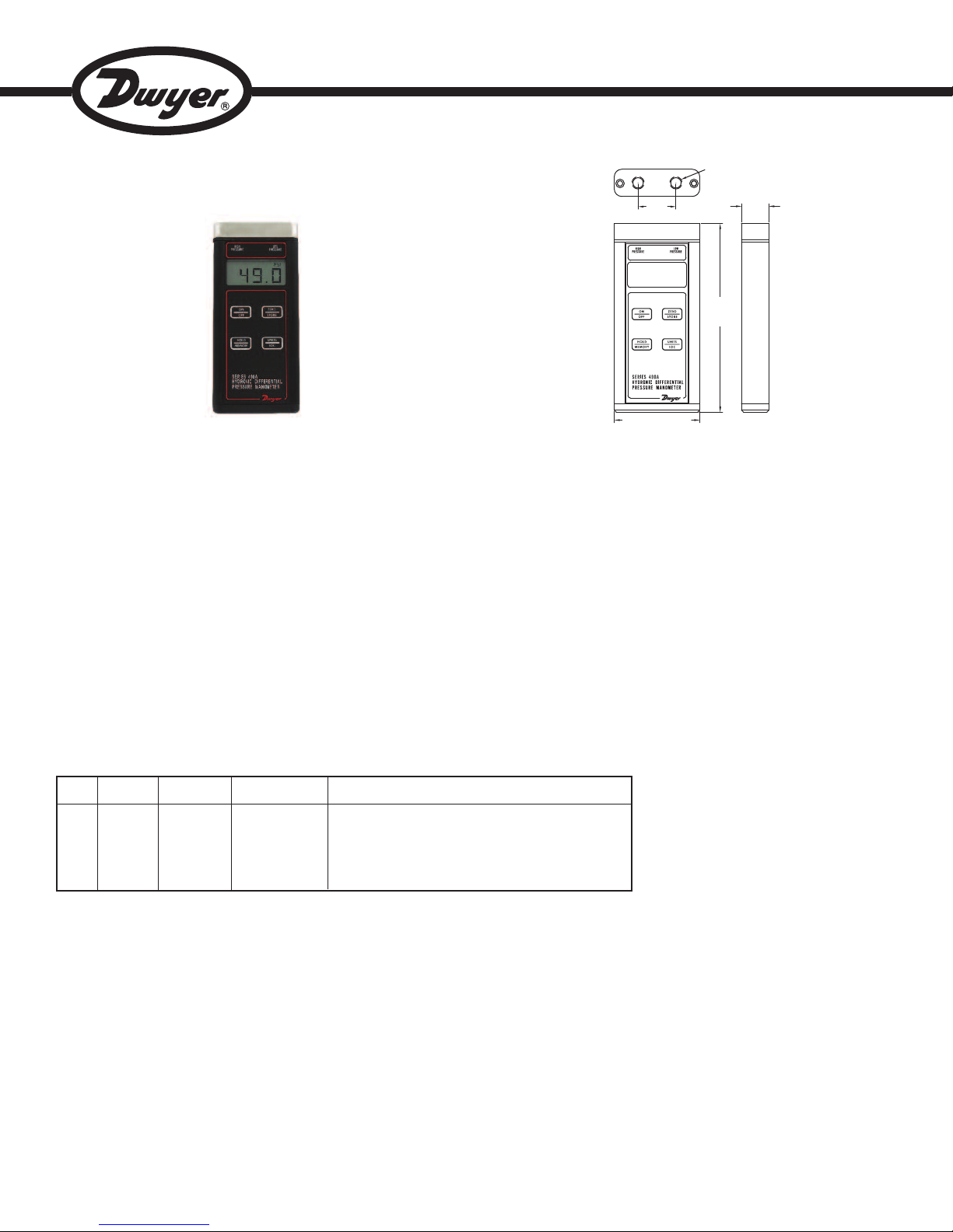
Series 490A Hydronic Differential Pressure Manometer
6-15/64
[158.27]
29/32
[22.86]
2-53/64 [71.73]
1/8 NPT
1-1/4
[31.75]
Specifications - Installation & Operating Instructions
Bulletin D-24A
Series 490A Hydronic Differential Pressure Manometer are versatile, hand-held,
battery operated manometers available in several basic ranges for positive or
positive differential pressure measurement and can tolerate most liquid media
compatible with 316LSS. A memory function allows storage of up to 40 readings for
later recall and a backlight provides auxiliary lighting for hard-to-see locations.
Standard are a hold feature and both visual and audible overpressure alarms. A
new feature added to the Series 490A is a field adjustable damping, independent
viewable high/low pressure readings, and low range increased resolution. This
allows the user to choose the level of display averaging rate corresponding to the
fluctuation level common in many applications. A 9 V alkaline battery is included
that provides up to 100 hours of operation.
Model
490A-1
490A-2
490A-3
490A-4
490A-5
490A-6
English
Range
0 to 15 psi
0 to 30 psi
0 to 50 psi
0 to 100 psi
0 to 500 psi
0 to 200 psi
Metric
Range
0 to 103.4 kPa
0 to 206.9 kPa
0 to 344.8 kPa
0 to 689.5 kPa
0 to 3448 kPa
0 to 1379 kPa
Maximum
Pressure
30 psi (2.7 bar)
60 psi (4.13 bar)
100 psi (6.89 bar)
200 psi (13.78 bar)
1000 psi (68.9 bar)
400 psi (27.57 bar)
Available Engineering Units
psi, in w.c., in Hg, cm w.c., mm Hg, kPa, hPa, mbar, bar, oz/in
psi, in w.c., in Hg, cm w.c., mm Hg, kPa, hPa, mbar, bar, oz/in
psi, in w.c., in Hg, cm w.c., mm Hg, kPa, hPa, mbar, bar, oz/in
psi, in w.c., in Hg, cm w.c., mm Hg, kPa, hPa, mbar, bar, oz/in
psi, in w.c., in Hg, cm w.c., mm Hg, kPa, hPa, mbar, bar, oz/in
psi, in w.c., in Hg, cm w.c., mm Hg, kPa, hPa, mbar, bar, oz/in
SPECIFICATIONS
Service: Compatible gases & liquids.
Wetted Materials: 316 SS; -3V option: 316LSS, Buna-N, silicone, grease, PTFE,
brass 360, copper, reinforced acetal copolymer; -HKIT option: 316LSS, PTFE,
brass, copper.
Accuracy: ±0.5% FS from 60 to 78°F (15.6 to 25.6°C); ±1.5% FS from 32 to 60°F
and 78 to 104°F (0 to 15.6°C and 25.6 to 40°C).
Pressure Hysteresis: ±0.1% FS.
Pressure Limits: See chart
Temperature Limits: Operating: 0 to 140°F (-17.8 to 60°C); Process with -HKIT
option: -20 to 180°F (-29 to 82°C); Storage: -4 to 176°F (-20 to 80°C).
Display: 4-digit LCD (.425˝ H x .234˝ W digits).
Resolution: See chart.
Process Connections: Two 1/8˝ (3.18 mm) female NPT; -HKIT option: Two 1/4˝
male 45° flare fittings.
Power Requirements: 9 V alkaline battery, installed non-functional, user
replaceable.
Weight: 14.1 oz (400 g); -HKIT option: 3.6 lb (1.63 kg).
Agency Approvals: CE.
2
2
2
2
2
2
www.GlobalTestSupply.com
Find Quality Products Online at: sales@GlobalTestSupply.com
Page 2

ATTERY INSTALLATION
B
he unit is shipped with a separate 9 volt alkaline battery which must be installed
T
efore operation. Remove the two screws holding the bottom endcap in place and
b
emove the endcap. Connect the battery to the enclosed battery clip, making sure
r
to observe correct polarity. Be careful not to trap wires between the battery, case,
or foam pads which retain the battery. This could make it difficult to install the battery
or remove it later for replacement. Be sure that the rubber gasket is properly seated
n the gasket channel of the endcap and replace endcap. Note that the endcap will
i
nly fit one way because the holes are slightly off-center. Place the Z shaped wrist
o
trap clip in one of the screw recesses and replace the screws. Do not over tighten
s
he screws. Attach the wrist strap to the clip. Note: On –HKIT option 490A, the
t
rubber boot will have to be pulled back to have access to the battery compartment.
AUTOMATIC RESOLUTION ADJUSTMENT
For all ranges, the series 490A will automatically move the decimal place one point
o the left when reading in the bottom 10% of its calibrated range. This allows the
t
ser to gain a higher resolution reading for lower static or differential pressure
u
eadings.
r
ELECTING PRESSURE UNITS
S
Up to seven pressure units are available. The display will indicate the current
selection. To change to different units, use the UNITS/LOC button. Each press of
the button will cause an advance to the next choice. The selected units will remain
n the memory even when the power is shut off. This way, the user preferences will
i
lways be displayed after the initial selection.
a
When battery replacement becomes necessary, use only a 9 volt alkaline type such
s a Duracell
a
abeled heavy-duty are not recommended because of the increased potential for
l
eakage. Alkaline batteries are also a better value because they last up to three
l
times longer in this device.
Low Battery Indicator
A weak battery can cause improper operation or inaccurate measurements. A low
attery indicator is provided on the display to show when the battery needs
b
eplacement.
r
AT indicator is illuminated. Replace the battery with a new one. Do not leave an
B
xhausted battery in the unit due to potential leakage.
e
N-OFF OPERATION
O
Press the ON/OFF button once to turn the unit on. Once on, press the ON/OFF
button for more than 5 seconds to turn the unit off. If the manometer is left on with
no activity for approximately 20 minutes, the unit will turn itself off to conserve the
battery.
ZEROING PRESSURE READING
Potential inaccuracy due to temperature effects can be minimized by re-zeroing
immediately before use. To zero the display, vent both ports to the atmosphere so
no pressure is applied to either port. Press the ZERO/STORE button and ---- will
be momentarily displayed as zeroing occurs. Zeroing is not possible when the
memory mode is in use. It must be done before selecting that function.
If the unit is accidentally zeroed with pressure applied to one of the ports, the
pressure reading might display incorrectly. To correct, vent the pressure ports to
atmosphere and press the ZERO/STORE button to zero the unit.
BACKLIGHT
The Model 490A includes a display backlight to allow use in the dark or in poor
lighting conditions. Pressing the ON/OFF button toggles the backlight on or off. With
the 490A on, press the ON/OFF button to toggle the backlight on or off. The
backlight will remain lit for approximately 2 minutes after which it will turn itself off
to conserve battery life.
OTICE
N
®
N 1604, Eveready
M
Although the unit might appear to function and indicate properly,
the accuracy of readings cannot be guaranteed when the LOW
®
22, or equivalent. Zinc-carbon types, often
5
ISPLAY HOLD
D
In situations where a reading needs to be temporarily retained, the Model 490A
includes a display hold feature which freezes the current reading and holds it on
the display until it is cleared. To activate this operation, press the HOLD/MEMORY
utton when the desired pressure is displayed. A HOLD indicator will appear on the
b
isplay to indicate that the reading shown is frozen. To return to normal operation,
d
ress the HOLD/MEMORY button again. The HOLD indicator will disappear and
p
the current pressure will be shown.
MEMORY FUNCTION
A memory function is included in the Model 490A that allows users to store up to 40
ressure readings for later review or recording. The readings are stored in non-
p
olatile memory so they will be retained even if the unit is shut off or the battery is
v
emoved.
r
toring Pressure Readings
S
o store a reading, press and hold the HOLD/MEMORY button until ST01 displayed.
T
Next, press the ZERO/STORE button to safe the current reading to the ST01
memory location. A beep will sound indicating that the reading has been saved. As
each reading is saved, the memory location display will advance to the next number.
To resume pressure measurement, press the HOLD/MEMORY button again. Note
that in the memory mode, the display zero function is not available. To zero the
display, exit the memory mode and then press the ZERO/STORE button.
Viewing Stored Readings – Selecting a Location
To view the contents of the memory, press and hold the HOLD/MEMORY button
until RD01 is displayed. Next, press UNITS/LOC to view other memory locations.
To resume pressure measurement, press the HOLD/MEMORY button again.
Clearing Memory
To clear the contents of the memory, press and hold the HOLD/MEMORY button
until CLR is displayed. Next, press the ZERO/STORE button to clear all previously
stored readings. During this operation --- will be displayed. Once the memory is
cleared, the current pressure will be displayed.
Exiting Memory Mode
To exit the memory mode, press the HOLD/MEMORY button again and the unit will
return to normal operation.
PRESSURE CONNECTION
Measuring Single Pressure
To measure single positive pressure, connect the tubing to the port marked “High
Pressure” and vent the opposite port to the atmosphere.
Measuring Differential Pressure
To measure differential pressure, connect the higher positive pressure to the port
marked “High Pressure” and the lower positive pressure to the port marked “Low
Pressure”. The manometer will indicate the difference between the two.
Overpressure Alarm
A visual indicator and audible alarm are provided to alert the user that pressure has
exceeded the operating range of the unit. Exceeding the range will not damage it
or affect calibration as long as the maximum rated pressure is not exceeded. The
maximum pressure for all units is shown on the rear label and on page 1 of these
instructions.
CAUTION
rupture the housing, and/or cause personal injury.
Find Quality Products Online at: sales@GlobalTestSupply.com
Do not exceed the maximum rated pressure of the manometer.
Doing so will cause permanent damage to the sensor, may
www.GlobalTestSupply.com
Page 3

DAMPENING FUNCTION
BLEED
F
ITTING
5
-1/4
[
133.35]
1
-21/64
[33.73]
10-2/5
[
264.2]
The dampening feature allows users to enter a dampening number from 1 to 16
(default value = 2). Entering a larger number increases the amount of readings that
re averaged for each display update.
a
n order to access the dampening feature:
I
. Press and hold the HOLD/MEMORY button for 7 seconds until DAMP is
1
displayed.
2. Once DAMP is selected, a number is shown in the upper right portion of the
LCD, along with the current pressure reading. This number is the dampening
umber. Adjust the number up by pressing the ZERO/STORE button or down
n
y pressing the UNITS/LOC button. The LCD update rate slows as the number
b
ncreases from 1 to 16. Therefore, for best results, choose the smallest number
i
hat provides a stable pressure reading.
t
3. Once the pressure reading is stable, press the HOLD/MEMORY button to store
the dampening value.
NDEPENDENT HIGH OR LOW STATIC PRESSURE READINGS
I
his feature allows the user to select the pressure source to be shown on the LCD.
T
he selections are LOW (-), HIGH (+), or DIFF (HIGH – LOW) without disconnecting
T
any process connections.
1. Press and hold the HOLD/MEMORY button for 9 seconds until SRCE is
displayed, then release.
. Next, press the UNITS/LOC button to change the source to the one desired.
2
. Press the ZERO/STORE, or ON/OFF or HOLD/MEMORY button to store the
3
ource and resume pressure measurement. To return to any other pressure
s
source reading, please return to step 1. Note: The unit will default to DIFF when
powered on, to return to a differential pressure reading DIFF (HIGH-LOW)
simply turn the unit off and then back on.
OPTIONAL 3-WAY VALVE
For certain hydronic applications, it is beneficial to measure the differential pressure
with the assistance of the optional attached 3-way valve. (See Fig. A)
egin with valve V1 open and valves V2 and V3 closed. (See Fig. B) Slowly open
B
2 and V3. Once the pressure has stabilized and is equal on the high and low side,
V
1 can be closed and normal operation can proceed. To ensure proper pressures
V
will be detected by the 490A, use the bleed fitting provided with this valve package.
(See Fig. A) Before applying pressure to the process connections, turn V1 to the
open position and back off the bleed screw. Next apply pressure. After the flowing
iquid is free of bubbles, retighten the bleed screw. Before taking the 490A offline
l
rom the process, open V1 then close V2 and V3.
f
Figure A
Figure B
Find Quality Products Online at: sales@GlobalTestSupply.com
www.GlobalTestSupply.com
Page 4

OPTIONAL HYDRONIC KIT (-HKIT Option)
7-5/64 [179.78]
11-55/64
[301.23]
3-5/32
[80.17]
3-5/32
[80.17]
LOW PRESSURE
BLEED FITTING
HIGH
PRESSURE
BLEED
FITTING
2-21/32
[67.47]
2X Ø5/16
[Ø7.94]
LOW PRESSURE
BLEED FITTING
V1
HIGH PRESSURE
BLEED FITTING
V2 V3
For hydronic valve balancing, Dwyer offers a full comprehensive kit of components
to be able read pressure across valves by tapping the pressure test ports on either
side of the valve or pump. The kit is comprised of two sets of 60˝ hoses with integral
ball valves, 3 pairs of various size gage piercing adapters, adapters for various
installations and a 3 way valve. The 3 way valve allows for isolation of pressure,
equalization between high /low and bleeding of lines to evacuate air or particulate.
(See Fig. C). Please use following procedure as a guide when reading differential
pressure across a hydronic valve or pump.
1. Begin with valve V1 open and valves V2 and V3 closed. (See Fig. D) Verify the
integral ball valves on the red and blue hoses are in the open position. Then
slowly open valves V2 and V3.
2. Once the pressure has stabilized and is equal on the high and low side, valve
V1 can be closed and normal operation can proceed.
3. To ensure proper pressures will be detected by the 490A, use the bleed fittings
for the high & low pressure sources on either side of the 3-valve manifold
assembly. (See Figure D) These can be adjusted with the use of the adjustable
wrench in the kit. PVC tubing has also been provided for connection to the bleed
fitting giving the ability to control the bleeding into a container or reservoir. Once
the lines are clear of pockets of air, close each bleed fitting with the wrench
provided.
4. With valve V1 closed, bleed fittings tightened, valves V2 and V3 open, take the
necessary readings.
5. Once the readings are completed, it is best practice to close off the integral ball
valves in the red and blue hoses and leave valves V2 and V3 open. Then using
the bleed fittings once more, loosen and bleed out the pressurized fluid or gases.
The PVC tubing can be used once more to control the bleeding of the fluid into
a container or reservoir.
6. Maintaining the integral hose ball valves in the closed position, disconnect from
the pressure test ports.
490-X-HKIT Field Replacement Parts
Model
A-HKIT-AFIT
A-HKIT-BFIT
A-HKIT-HOSES
A-HKIT-500
A-HKIT-500XL
A-HKIT-510
UHH-STRAP
A-47X-BOOT
A-203
Please call our customer service for pricing and availability at 219-879-8000 or
email: quotes@dwyer-inst.com
Description
Adapter fitting replacement kit including:
Straight adapter, 1/4˝ Male NPT X 1/4˝ - 45° flare (2 per kit)
1/4˝ SAE 45° flare seal cap and gasket (2 per kit)
90° union elbow, 1/4˝ - 45° flare X 1/4˝ - 45° flare (2 per kit)
90° male elbow, 1/4˝ male NPT X 1/4˝ - 45° flare (2 per kit)
Bleed fitting assembly (2 per kit)
60˝ blue charging hose with valve
60˝ red charging hose with valve
Piercing gauge adapter 1/8˝ DIA x 1-1/2˝ Length (2 per kit)
Piercing gauge adapter 1/8˝ DIA x 3˝ Length (2 per kit)
Piercing gauge adapter 1/16˝ x 1-1/2˝ Length (2 per kit)
Pipe or carry strap
Rubber boot
PVC tubing 1/4˝ OD x 1/8˝ ID. Ordered per foot
Figure C
Figure D
MAINTENANCE/REPAIR
Upon final installation of the Series 490A, no routine maintenance is required. The
Series 490A is not field serviceable and should be returned if repair is needed. Field
repair should not be attempted and may void warranty.
WARRANTY/RETURN
Refer to “Terms and Conditions of Sale” in our catalog and on our website. Contact
customer service to receive a Return Goods Authorization Number before shipping
the product back for repair. Be sure to include a brief description of the problem
plus any additional application notes.
Duracell® is a registered trademark of The Gillette Company
®
Everready
is a registered trademark of The Everready Battery Company, Inc.
Find Quality Products Online at: sales@GlobalTestSupply.com
www.GlobalTestSupply.com
 Loading...