

Dwyer Instruments 1900 Series, 1910-00, 1910-0, 1910-1, 1910-10 Installation And Operating Instructions Manual
...Page 1
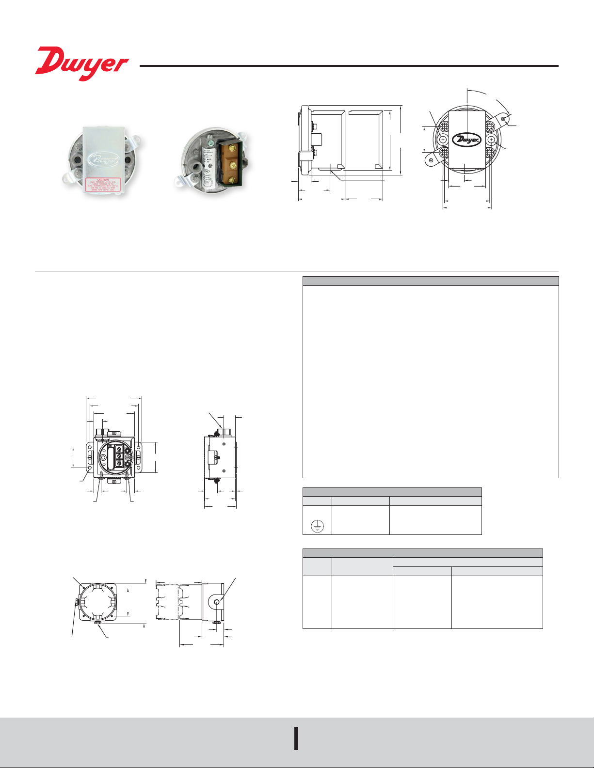
Series 1900 Pressure Switch
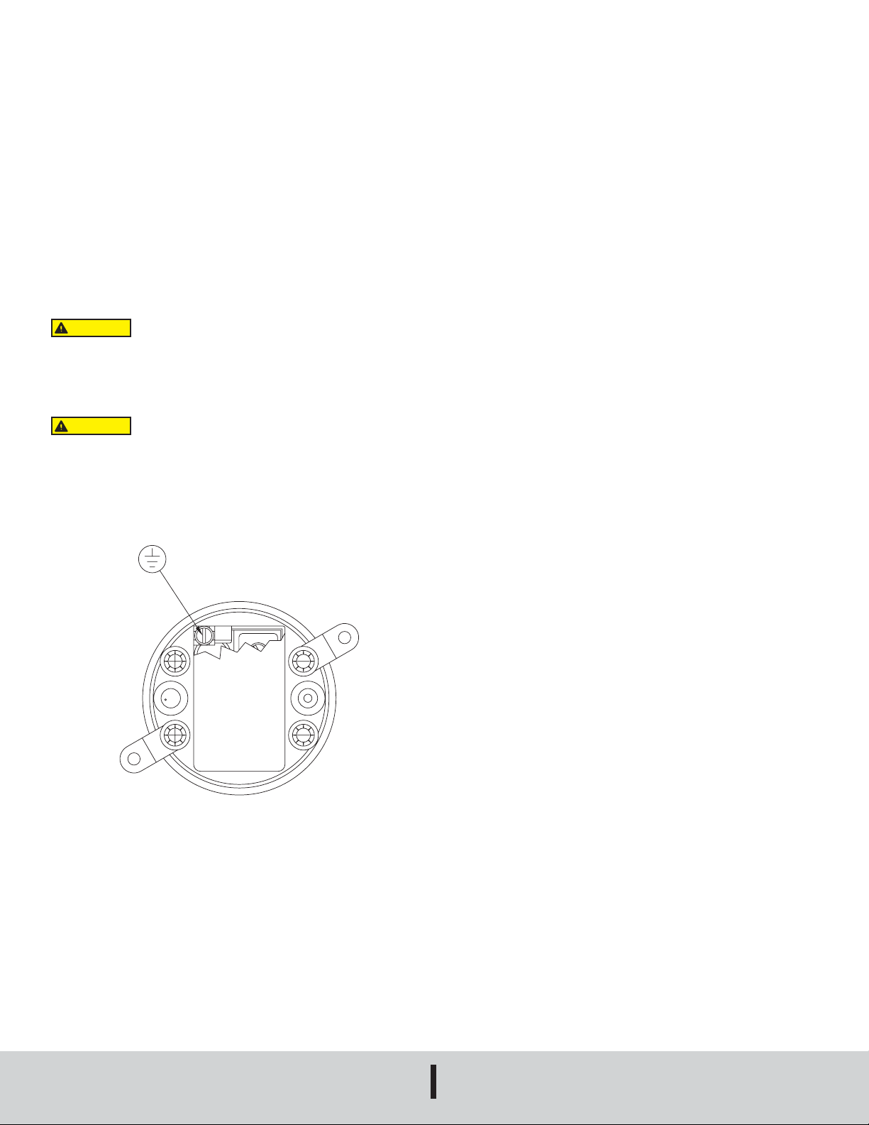
POWER INPUT
TERMINALS
+ –
GROUNDING
SCREW
®
Specications - Installation and Operating Instructions
1/8 FEMALE NPT
HIGH PRESSURE
CONNECTION
3
41/64
[16.27]
1-19/32
[40.48]
2-11/32 [59.53]
1-3/4 [44.45]
CLEARANCE
FOR
COVER REMOVAL
[76.20]
ø 7/8 [22.23]
CONDUIT
CONNECTION
ø 3-1/2
[88.90]
1-5/16
[33.32]
TYP
51/64
[20.24]
1-7/8
[47.63]
2-9/32 [57.94]
2-7/16 [61.90]
Bulletin E-56
60° TYP
(2) ø 3/16 [4.76]
MOUNTING
HOLES ON
A 4-3/16
[106.36] B.C.
1/8 FEMALE
NPT LOW
PRESSURE
CONNECTION
Series 1910 pressure switch. All
pressure and electrical connections
and set point adjustments are on one
side for easy installation.
Advanced design and precision construction permit these switches to perform many
of the tasks of larger, costlier units. Designed for air conditioning service, they also
serve many uidics, refrigeration, oven and dryer applications. For use with air and
non-combustible gases. Series 1900 Pressure Switches are available with set points
of 0.07 to 20 inches water column. Set point adjustment can be made easily - before or
after installation. Range screw is inside conduit enclosure to help prevent tampering.
For easy mounting and access, pressure and electrical connections and set point
adjustment are located on one side. This permits installation in corners or spaces too
small for other switches.
SPECIAL MODELS & ACCESSORIES
Special close coupled street elbow for right angle pressure connections. Can be
installed on switch anytime. Zinc plated aluminum.
5-7/16 [138.1]
4-3/4 [120.7]
4 [101.6]
7/8 [22.22]
Ø5/16
[Ø7.938]
3/4 [19.05]
HIGH PRESSURE
CONNECTION 1/8 N.P.T.
Weatherproof Housing
16 ga. steel enclosure with gasketed cover (NEMA 4) for wet or oily conditions.
Withstands 200 hour salt spray test. Wt. 5 Ibs. (2.3 kg). Switch must be factory installed.
Change 1910 base number to 1911 and add -WP sufx. Example: 1911-1-WP.
4X Ø.281
[7.14]
1/8 FEMALE
NPT HIGH PRESSURE
CONNECTION
LOW PRESSURE
CONNECTION 1/8 N.P.T.
2X 6-1/8
[155.58]
2X 4-1/4
[107.95]
1/8 FEMALE NPT
LOW PRESSURE
CONNECTION
Series 1910 switch with conduit
enclosure off. Shows electric switch
and set point adjustment screw.
1/2 NPT WEATHERPROOF
ELECTRICAL CONNECTION
3 [76.20]2 [50.80]
3/4 [19.05]
1-1/4
[31.75]
6-1/2 [165.10]
CLEARANCE FOR
COVER REMOVAL
6-5/8
[168.28]
3 [76.20]
3-1/8
[79.38]
1/2 NPT
PROCESS CONNECTION
1-1/8 [28.58]
3/32
[2.381]
3X 1-1/16
[26.99]
3 [76.20]
The Dwyer-engineered force-motion amplier increases the leverage of
diaphragm movement and results in a switch with excellent sensitivity and
repeatability.
SPECIFICATIONS
Service: Air and non-combustible, compatible gases.
Environment: Standard model intended for indoor use.
Wetted Materials: Consult factory.
Temperature Limits: -30 to 180°F (-34 to 82.2°C) (32°F for non dry air).
Pressure Limits: 45 in w.c. (11.2 kPa) continuous, 10 psig (68.95 kPa) surge.
Humidity Limit: 80% RH (non-condensing).
Altitude Limit: 6560 ft (2000 m) max.
Switch Type: Single-pole double-throw (SPDT).
Repeatability: ±3%.
Electrical Rating: 15 A @ 120-480 VAC (~), 60 Hz. Resistive 1/8 HP @125
VAC(~), 1/4 HP @ 250 VAC(~), 60 Hz. Derate to 10 A for operation at high cycle
rates.
Electrical Connections: 3 screw type, common, normally open and normally
closed.
Installation Category: III (transient over-voltage).
Process Connections: 1/8˝ female NPT.
Mounting Orientation: Diaphragm in vertical position. Consult factory for other
position orientations.
Set Point Adjustment: Screw type inside conduit enclosure.
Pollution Degree: 2.
Weight: 1lb. 4.5 oz. (581 g).
Agency Approvals: CE, UL, CSA, FM.
EXPLANATION OF SYMBOLS
Symbol Publication Description
IEC 60417 - 5032
~
IEC 60417 - 5019
SERIES 1910 SWITCHES - MODELS OPERATING RANGES, DEADBANDS
Operating Range,
Model
in w.c.
1910-00
0.07 to 0.15
1910-0
0.15 to 0.5
1910-1
0.40 to 1.6
1910-5
1.40 to 5.5
1910-10
3.0 to 11.75
1910-20
4.0 to 20.0
Alternating current
Protective conductor terminal
Approximate Dead Band
At Min. Set Point At Max. Set Point
0.04
0.10
0.15
0.30
0.40
0.40
0.04
0.10
0.16
0.30
0.40
0.50
Explosion-Proof Housing
NEMA 7, 9 NEMA 3. (7 lbs). Switch must be factory installed. Change model to 1911
and add -EXPL sufx. Example: 1911-1-EXPL. Aluminum base and cover rated Class
I, Groups C & D, Div. 1. Class II, Groups E, F, & G, Div. 1.
DWYER INSTRUMENTS, INC.
P.O. BOX 373 • MICHIGAN CITY, INDIANA 46360, U.S.A.
Phone: 219/879-8000
Fax: 219/872-9057
www.dwyer-inst.com
e-mail: info@dwyermail.com
Page 2
INSTALLATION
1. Select a location that is free from excessive vibration, corrosive atmosphere and
where the ambient temperature is within the limits for these switches.
2. Mount standard switches with the diaphragm in a vertical plane and with switch
lettering and nameplate in an upright position. Some switches are position
sensitive and may not reset properly unless they are mounted with the diaphragm
vertical. (Special units can be furnished for other than vertical mounting
arrangements if required.)
3. Connect switch to source of pressure, vacuum or differential pressure. Metal tubing
with 1/4˝ O.D. is recommended, but any tubing which will not restrict the air ow
can be used. Connect to the two 1/8˝ female NPT pressure ports as noted below:
• Differential pressures - connect pipes or tubes from source of greater pressure
to high pressure port marked HI-PR and from source of lower pressure to low
pressure port marked LO-PR.
• Pressure only (above atmospheric) - connect tube from source of pressure to
high pressure port. The low pressure port is left open to atmosphere.
• Vacuum only (below atmospheric pressure) - connect tube from source of
vacuum to low pressure port. The high pressure port is left open to atmosphere.
CAUTION
4. Electrical connections to the standard single pole, double throw snap switch are
provided by means of screw terminals marked “common”, “norm open”, and “norm
closed”. The normally open contacts close and the normally closed contacts open
when pressure increases beyond the set point.
Power must be off while wiring connections are being made.
OPERATION
Pressure acting on the power diaphragm rotates the amplifying lever, which in turn
extends the range spring and rotates the snap switch input lever. When the set point
is reached, the snap switcch is actuated and the electrical contacts make or break.
ADJUSTMENT
To change the set point, proceed as follows:
A. Remove the snap-on cover from the conduit enclosure by loosening its retaining
screw and pulling rmly at its bottom end. Turn the slotted adjustment screw at
the top of range spring housing clockwise to raise the set point pressure and
counter-clockwise to lower the set point.
B. The recommended procedure for calibrating or checking calibration is to use a
“T” assembly with three rubber tubing leads, all as short as possible and the
entire assembly offering minimum ow restriction. Run one lead to the pressure
switch, another to the manometer of known accuracy and appropriate range, and
apply pressure through the third tube. Make nal approach to the set point very
slowly. Note that manometer and pressure switch will have different response
times due to different internal volumes, lengths of tubing, uid drainage etc. Be
certain the switch is checked in the position it will assume in use, i.e. with
diaphragm in a vertical plane and switch lettering and nameplate in an upright
position.
C. For highly critical applications it is a good idea to check the set point adjustment
and reset it as necessary once or twice in the rst few months of operation. This
will compensate for any change in initial tension which may occur in the spring
and diaphragm. For most applications this change will not be signicant and no
resetting will be required.
CAUTION
5. Switch loads should not exceed the maximum specied current rating of 15 amps
resistive. Switch capabilities decrease with high load inductance or rapid cycle
rates. Whenever an application involves either of these factors, the user may nd
it desirable to limit the switched current to 10 amps or less in the interest of
prolonging switch life.
Do not exceed the specied voltage rating. Permanent damage
not covered by warranty may result.
MAINTENANCE
Moving parts of these switches are sealed in and are permanently tamper proof. The
single adjustment is that of the set point. Care should be taken to keep the switch
reasonably dry and free from dust or dirt. No lubrication or unusual precautions are
required for normal use.
DWYER INSTRUMENTS, INC.
P.O. BOX 373 • MICHIGAN CITY, INDIANA 46360, U.S.A.
Phone: 219/879-8000
Fax: 219/872-9057
www.dwyer-inst.com
e-mail: info@dwyermail.com
Page 3

Presostatos Serie 1900
POWER INPUT
TERMINALS
+ –
GROUNDING
SCREW
®
Instrucciones de Montaje y Operación
41/64
[16.27]
1-19/32
[40.48]
2-11/32 [59.53]
COVER REMOVAL
1-3/4 [44.45]
CLEARANCE
FOR
1/8 FEMALE NPT
HIGH PRESSURE
CONNECTION
3
[76.20]
ø 3-1/2
[88.90]
ø 7/8 [22.23]
CONDUIT
CONNECTION
1-5/16
[33.32]
TYP
51/64
[20.24]
1-7/8
[47.63]
2-9/32 [57.94]
2-7/16 [61.90]
Bulletin E-56
60° TYP
(2) ø 3/16 [4.76]
MOUNTING
HOLES ON
A 4-3/16
[106.36] B.C.
1/8 FEMALE
NPT LOW
PRESSURE
CONNECTION
Series 1910 pressure switch. All
pressure and electrical connections
and set point adjustments are on one
side for easy installation.
El diseno avanzado y la constucción prcisa permitne que estospresostatos reemplacen
a otros de mayor precio y tamaño. Sirven para uso en acondicionamiento de aire,
hornos, secaderos y aplicaciones en uídica y refrigeración. Aptos para uso en aire y
gases no combustibles. Ranges disponibles desde 0.07˝ a 20˝ de C.A.
El ajuste puede ser antes o después de instalado. El tornillo de ajuste está oculto
dentro de la cubierta de conexiones para evitar manipuleo indebido. El ajuste, las
conexiones de presión y elelctricas están de un solo lado para facilitar el montaje. Esto
permite la instalación en rincones o lugares estrechos.
MODELOS Y ACCESORIOS ESPECIALES
Accesorio Dwyer A-329
Codo de conexión an ángulo recto. Puede instalarse en cualquier momento.
Construcción en aluminio zincado.
5-7/16 [138.1]
4-3/4 [120.7]
4 [101.6]
7/8 [22.22]
Ø5/16
[Ø7.938]
3/4 [19.05]
HIGH PRESSURE
CONNECTION 1/8 N.P.T.
Gabinete Hermético
Gabinete de acero cal. #16 para ambientes extremadamente húmedos o aceitosos.
Peso 5 lb. Presóstato instalado en fábrica. Especique “WP” más el nro. de modelo.
4X Ø.281
[7.14]
1/8 FEMALE
NPT HIGH PRESSURE
CONNECTION
LOW PRESSURE
CONNECTION 1/8 N.P.T.
2X 6-1/8
[155.58]
2X 4-1/4
[107.95]
1/8 FEMALE NPT
LOW PRESSURE
CONNECTION
Series 1910 switch with conduit
enclosure off. Shows electric switch
and set point adjustment screw.
1/2 NPT WEATHERPROOF
ELECTRICAL CONNECTION
3 [76.20]2 [50.80]
3/4 [19.05]
1-1/4
[31.75]
6-1/2 [165.10]
CLEARANCE FOR
COVER REMOVAL
6-5/8
[168.28]
3 [76.20]
3-1/8
[79.38]
1/2 NPT
PROCESS CONNECTION
1-1/8 [28.58]
3/32
[2.381]
3X 1-1/16
[26.99]
3 [76.20]
The Dwyer-engineered force-motion amplier increases the leverage of
diaphragm movement and results in a switch with excellent sensitivity and
repeatability.
SPECIFICATIONS
Servicio: Aire y no combusibles, gases compatibles.
Ambiente: Para uso en interiores.
Materiales mojados: Consulte con la fábrica.
Límites de temperature: -30 to 180°F (-34 to 82.2°C).
Límites de presión: 45 in w.c. (11.2 kPa) continuo, 10 psig (68.95 kPa) marejada.
Humedad límite: 80% RH (sin condensación).
Altitud límite: 6560 ft (2000 m) máximo.
Tipo de conmutador: SPDT.
Repetibilidad: ±3%.
Calicación eléctrica: 15A @ 120 to 480 VAC, 60 Hz resistador 1/8 HP @ 125
VAC, 1/4 HP @ 250 VAC, 60 Hz desclasique a 10A para la operación en las tasas
de ciclo de alta.
Conexiones eléctricas: 3 tipo de tornillo, C, N.O., N.C.
Categoría de Instalación: III (sobretensión transitoria).
Conexiones a proceso: 1/8˝ NPT hembra.
Orientación de montaje: Diafragma en posición vertical. Consulte con la fábrica
para las orientaciones otra posición.
Ajuste del punto de ajuste: Tipo de tornillo interior de la caja del conducto.
El grado de contaminación: 2.
Peso: 1 lb 4.5 oz (581 g).
Aprobaciones de las agencias: CE, UL, CSA y FM. Opcional EXPL caja prueba
de explosions no posee ninguna autorización de agencias.
EXPLICACIÓN DE LOS SÍMBOLOS
Symbol Publication Description
IEC 60417 - 5032
~
IEC 60417 - 5019
PRESOSTATOS SERIE 1910 - RANGOS Y BANDA MUERTA
Modelo Rango
1910-00
0,07 to 0,15
1910-0
0,15 to 0,5
1910-1
0,40 to 1,6
1910-5
1,40 to 5,5
1910-10
3,0 to 11,75
1910-20
4,0 to 20,0
Corriente alterna
Terminal del conductor de protector
Banda Muerta
Aj. Minimo Aj. Máximo
0,04
0,10
0,15
0,30
0,40
0,40
0,04
0,10
0,16
0,30
0,40
0,50
Gabinete Antiexplosivo
Base de hierro fundido y tapa en aluminio. Peso aprox. 5 lb. Especique “EXPL” más
el nro. de modelo.
DWYER INSTRUMENTS, INC.
P.O. BOX 373 • MICHIGAN CITY, INDIANA 46360, U.S.A.
Phone: 219/879-8000
Fax: 219/872-9057
www.dwyer-inst.com
e-mail: info@dwyermail.com
Page 4

INSTALACION
1. Elija un sitio donde no haya vibraciones excesivas, atmósfera corrosiva, y la
temperatura se mantenga dentro de los límites tolerados por el presóstato (vea las
especicaciones).
2. Instale el presóstato con el diafragma en un plano vertical, y el Logo de DWYER y
la escritura de la etiqueta en la parte superior. Algunos instrumentos son sensibles
a la posición y no conmutarian adequadamente si el diafragma no está vertical.
Si se requiere, se pueden suministrar unidades especiales para montaje en distinte
posición.
3. Conecte el presostato a proceso por medio de los conectores hembra NPT de 1/8˝.
Se recomienda para esto., utilizar tubo metalico de 1/4˝ diam. ext. sin embargo
puede usarse cualquier tubo que no retrinja el paso de aire. Recuerde que:
• Presión diferencial: Conecte la alta presion a HI-PR (alta presion) y la baja a
LO-PR (baja presion).
• Presión: conecte la presión (superior a la atmosférica) a HI-PR, dejando LO-PR
abierto a la atmósfera.
• Vacío: igual gue para Presión, pero invirtiendo las conexiones a proceso. Deje
el conector no utilizado abierto a la atmósfera.
CAUCIÓN
4. Las conexiones electricas se efectúan mediante terminales a tornillo, marcados
“ Common” (Común); “Norm Open” (Normal Abierto) y “Norm Closed: ( Normal
Cerrado). Los contactos se invierten al incrementarse la presión por sobre el ajuste
(set point).
CAUCIÓN
lugar a.
5. La corriente no debe exceder do los 15 A sobre carga resistiva, La capaciedad
del interruptor decrece con cargas inductivas, o ciclos rápidos de conmutación.
Cuando estas condiciones se presenten, o se esté en dudas acerca de las
mismas, se recomienda limitar la corriente a 10 A para prolgar la vida util de
interuptor. Otro método consiste enaumentar la capacidad de corriente del
interruptor mediante un relé para alta corriente o contactor. Consulte al
Representante de DWYER en caso necesario.
El poder debe estar apagado mientras que las conexiones del
cableado se están realizando.
No exceda el valor nominal de tensión especicado. Daños
permanentes que no estén cubiertos por la garantía puede dar
OPERACION
La presión actúa sobre el diafragma, girando la palanea amplicadora. Esta a su vez,
extiende el resorte antagónico (de calibrasión) el que está mecánicamente vinculado
a la palanca actuadora del interruptor inversor: Al alcanzarse el valor preajustado,
la condición de los contactos se invierte, es decir el NA pasa cerrado, y el NC pasa
abierto.
AJUSTE
Para cambiar el ajuste, proceda de la siguiente manera:
A. Retire la tapa cubre-conexiones aojando el tornillo de retención, y tirando
rmemente de su extremo inferior. Gire el tornillo de ajuste en sentido horario
para incrementar la presión de actuación, o bien gírelo en sentido anti-horario
para disminuir la misma.
B. El procedimiento más seguro y simple para consequir una calibración correcta (o
la vericación) del punto de trabajo es la siguiente:
1. Conecte una tubería de goma de poca longitud desde el presóstato a una
T de conexión, otra desde la T a un manómetro de exactitud reconocida, y
otra desde una fuente disponible de presión.
2. Aplique presión lentamente, teniendo en cuenta gue el presóstato y el
manómetro pueden tener diferentes tiempos de reacción debido a
diferencias en volumen de aire, además de otras característcas mecanicas
diferentes. La aproximación nal al punto de trabajo debe ser muy lenta.
3. Asegúrese que el presóstato está en posición correcta de funcionamiento,
o por lo menos en la posición que será montado. Recuerde que el
funcionamiento correcto de la unidad corresponde a montaje vertical del
diafragma.
C. En aplicaciones muy críticas, es conveniente durante los primeros meses de
servicio vericar el punto de trabajo, y eventualmente restablecer el contacto
varias veces, para compensar cambios iniciales en la tension del resorte
antagónico, y diafragma. En la mayoría de los casos, esto no es necesario.
MANTENIMIENTO
Las partes móviles y contactos están sellados, siendo inalterables. El único ajuste
disponible es del punto de trabajo. Evite ingreso de suciedad y acumulación humedad.
No se requiere lubricación periódica.
©Copyright 2019 Dwyer Instruments, Inc. Printed in U.S.A.4/19 FR# 440232-00 Rev. 5
DWYER INSTRUMENTS, INC.
P.O. BOX 373 • MICHIGAN CITY, INDIANA 46360, U.S.A.
Phone: 219/879-8000
Fax: 219/872-9057
www.dwyer-inst.com
e-mail: info@dwyermail.com
 Loading...