

Page 1

Bulletin C-1205A-5
3
-1/2
(
88.90)
G
REY CASE
DISPLAY
R
ED PROTECTIVE SLEEVE
1-13/16
(
46.04)
7
-29/32
(200.82)
Model 1205A-5 Handheld CO Analyzer
Specifications - Installation and Operating Instructions
Model 1205A-5 Handheld CO Analyzer provides a simple, cost effective
answer to detecting and monitoring colorless, odorless, toxic carbon monoxide. The portable, battery operated unit measures CO from 0 to 2000 ppm
and can record maximum CO values. Use a Type K thermocouple (sold
separately) to measure temperatures. Simultaneously display two different functions on the large two-line alpha-numeric LCD. Quickly program
time, date, engineering units, language and other display functions. The
rotary dial allows easy function selections. The analyzer features auto
zeroing, battery indication, infrared printer link, and a backlight display for
low light areas. The Model 1205A-5 is ideal for ambient air monitoring in
residential and commercial markets, flue testing in small boilers, and source
investigation in areas where CO monitors have alarmed. The unit includes
a stainless steel flue probe with filter and flexible tubing, batteries and
instruction manual.
INTRODUCTION
The 1205A-5 meter tests CO levels in heating appliances, ambient air,
around fossil fuel appliances like cookers and grills. It also helps you test
residential and commercial CO alarms and also shows CO MAX - the maximum level of CO recorded.
The 1205A-5 can also be used as a digital thermometer, ideal for testing
hot water or refrigeration.
A large backlit display shows 2 readings, and all data can be printed via
an optional printer. The printout shows complete data and includes the
date and time.
The 1205A-5’s protective rubber boot has a magnet for “hands-free” operation when using probe to test combustion appliances and ambient air.
The 1205A-5 is controlled using 4 buttons and a rotary dial.
The four buttons (from left to right):
1. Power Switch to turn the meter on and off.
2. Print actual or frozen data and switch on and off the backlight.
3. Switch on and off the pump.
4. “Freeze” or hold data.
SPECIFICATIONS
Range: CO: 0 to 2000 ppm; Temperature: 32 to 1112°F (0 to 600°C).
Accuracy: CO: ±5% of reading; Temperature: ±5°F (2°C).
Display: Alpha-numeric LCD, dual digits.
Ambient Operating Temperature: 32 to 104°F (0 to 40°C).
Operating RH: 10 to 90% non-condensing.
Response Time: 20 to 30 seconds.
Sensor Type: Electrochemical cell.
Calibration: Auto zero function.
Flexible Tubing: 9 ft (3 m) polyurethane tubing with quick fit connec-
tor. Max. temperature: 180°F (82°C).
Flue Probe: 11.8˝ (30 cm) length, stainless steel with quick fit connector to aluminum handle. Max. temperature: 1100°F (600°C).
Temperature Probe: Type K thermocouple with mini-connector (sold
separately).
Power Requirements: (4) AA alkaline batteries, installed functional,
user replaceable.
Battery Life: 8 hours with alkaline batteries (continuous use without
backlight).
Weight: 1.5 lb (0.7 kg).
Agency Approval: CE.
BEFORE USING FOR THE FIRST TIME
Turn over the meter, remove the protective rubber sleeve and fit four
alkaline “AA” batteries in the battery compartment. Replace the battery
cover and protective rubber sleeve.
The buttons with UP, DOWN and ENTER arrows also change settings
such as date, time and the display’s top line.
The rotary dial changes the display’s second line and also accesses the
menu to allow changing the date, time, etc.
DWYER INSTRUMENTS, INC.
Phone: 219/879-8000 www.dwyer-inst.com
Figure 1 - Installing Batteries
P.O. Box 373 • Michigan City, IN 46360, U.S.A. Fax: 219/872-9057 e-mail: info@dwyer-inst.com
Find Quality Products Online at: sales@GlobalTestSupply.com
www.GlobalTestSupply.com
Page 2

Set the meter’s correct time, date, etc., after it is switched on and calibrated. See USING THE ROTARY DIAL to the right. The settings will
remain stored after the meter is turned off.
CHECK BEFORE USING EVERY TIME
• The particle filter is not dirty.
• The water trap and probe line are empty of water.
• All hose and thermocouple connections are properly made.
• The probe is sampling ambient FRESH air.
• The water trap and drain plug are fitted correctly to the instrument
• The temperature probe is connected, if required.
Switch ON the instrument by pressing .
SAFETY WARNING
This meter extracts combustion gases that may be toxic in relatively low
concentrations. These gases are exhausted from the back of the instrument. This meter must only be used in well-ventilated locations by
trained and competent persons after due consideration of all the
potential hazards.
CONTROLS
Switching ON
the meter
Switching
OFF the
meter
Press button to switch the unit ON in fresh air outside
the property to be tested. This lets the meter auto calibrate its sensors properly.
ON switch, on the meter beeps four times and displays
on its top line the time and model number. Its bottom
line counts down from 60 until the sensors are ready
to use - this normally takes 20 to 30 seconds but may
take longer as sensors get older. If the meter will not
auto calibrate, its sensors need to be replaced or
recalibrated by an authorized repair center.
When countdown is finished the display’s top line
shows the last sensor function and the bottom line displays whatever the rotary dial is turned to.
Press button to switch the meter OFF. The display
counts down with the pump on to clean the sensors
with fresh air - if the probe is connected, make sure
meter and probe are in fresh air.
Press HOLD/ENTER if you want to stop the countdown and return measurements.
USING THE ROTARY DIAL (STARTING FROM MENU):
Rotating the dial selects the display’s second line, unless MENU is
selected.
MENU
TIME &
DATE
TEMP
CO
CO MAX
BAT
TAKING MEASUREMENTS
Appliance Measurements
After the countdown is finished and the meter is correctly set up, put its’
probe into the appliance’s sampling point. The ideal sampling point is at
least two flue diameters downstream of any bend.
Put the probe tip in the flue center. With balanced flues, make sure the
probe is positioned far enough into the flue so no air can “back flush” into
the probe.
Rotate the dial to MENU and use the UP or DOWN
buttons to select the following function for change:
1 Time – Uses “Military” time as standard: 7am =
07:00, 7pm = 19:00.
2 Date – Select from MM/DD/YY, YY/MM/DD or
DD/MM/YY.
3 The display’s top line – select from the settings
listed below.
4 Temperature units – °F or °C.
5 The display screen contrast.
6 Language – Select from English, French, Spanish,
Italian & German.
7 Service – Password protected for authorized
service personnel only.
Displays Time and Date.
Displays the measured temperature in °F or °C.
If the temperature sensor is broken or open circuit it
displays 000.
Displays Carbon Monoxide (CO) values in PPM.
Displays the maximum CO value in PPM recorded during the test.
Displays estimated battery life.
If battery voltage falls below a preset limit, the display
flashes “LOW BAT.” every 10 seconds. See above to
change the batteries or use the optional main adapter.
Using UP/
DOWN/
ENTER
Buttons
Switching on
and off the
backlight
Printing Data
Switching
PUMP on/off
“Freezing” the
display
Press the DOWN button for more than 1 second to
change the display. The Rotary Dial changes the display’s bottom line.
For example, the meter will display CO on its top line
and Temperature on its bottom line if you turn the
rotary dial to TEMP and push the DOWN button until
CO is displayed on the top line.
Use the UP/DOWN/ENTER keys to change settings
(such as time) when the rotary dial is turned to MENU.
Press and release PRINT/BACKLIGHT quickly to
switch backlight.
Press for more than 1 second before releasing to start
the meter printing. Meter displays “PRINTING” until
this is completed.
Make sure the printer is switched on, ready to accept
data and its receiver is in line with the meter’s emitter
(on top of the meter).
The meter normally operates with the pump on. Press
PUMP quickly to turn the pump off and on.
When the pump is switched off, the meter displays
“PUMP OFF” approximately for 30 seconds.
Press HOLD/ENTER to freeze all readings. The display flashes and is printed by pressing the PRINT key.
Press HOLD/ENTER for “live” measurements.
Figure 2 - Taking an appliance test
Use the probe’s depth stop cone to fix it in flue diameters from 1/4 to 3/4
inch, 6 to 21 mm. Its maximum operating temperature is 1112°F/600°C.
Make sure you do not exceed the meter’s operating specifications.
In particular:
• Do not exceed the probe’s maximum temperature.
• Do not exceed the meter’s internal temperature operating range.
• Do not put the meter on a hot surface.
• Do not exceed the water trap’s levels.
• Do not let the meter’s particle filter become dirty and/or blocked.
View data and rotate the dial to see measurement changes as you make
adjustments.
Press HOLD first to “freeze” the readings before printing, then press PRINT.
Find Quality Products Online at: sales@GlobalTestSupply.com
www.GlobalTestSupply.com
Page 3
Ambient Air Measurements
When testing for CO in rooms, make sure the meter has been switched on
in OUTDOOR fresh air before the meter is calibrated.
PROBLEM SOLVING
If any problems are not solved with these solutions, contact an authorized
repair center.
After the countdown is finished and the meter is correctly set up, take the
meter into the room to be tested, make sure its pump is on and use the
probe to draw in ambient air for the meter to measure.
• Only switch on the meter in OUTDOOR, FRESH AIR.
• Do not exceed the meter’s internal temperature operating range.
• Do not put the meter on a hot surface.
• DO NOT expose yourself and others to dangerous levels of CO.
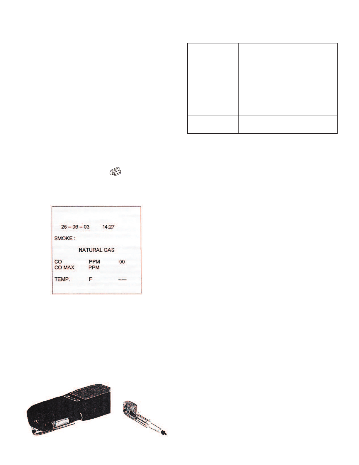
PRINTING TEST INFORMATION
An optional accessory for the 1205A-5 is an infrared thermal printer. Read
the manual supplied with the printer prior to operation. Connection to the
1205A-5 is detailed below:
• Infrared thermal printer – this does not require a cable to transmit the data but uses an infrared (IR) link similar to a TV remote
control. The IR emitter is positioned on the top of the 1205A-5
and the bottom of the printer. Ensure they are pointing at each
other and within 3 feet (1 meter), with no obstructions in the
way. Data may be lost if transmission is interrupted. Keep the
1205A-5 pointing at the printer until the printout has finished.
During combustion tests the 1205A-5 will print data on request. With the
meter showing the MAIN DISPLAY press and current data will be
sent to the printer.
The display will show “PRINTING” until data transmission is complete.
Below is an example of a typical printout:
• CO sensor error (----)
• Batteries not holding
charge
• Meter not running on
mains adapter
• Meter does not
respond to flue gas
• Erratic temperature
readings or 000 on
display
RECALIBRATION AND SERVICE
Although sensor life is typically more than two years, the meter should be
re-calibrated and serviced annually to stop any long-term sensor or electronics drift or accidental damage.
Local regulations may require more frequent calibration.
MAINTENANCE
Upon final installation of the Model 1205A-5 Handheld CO Analyzer and
the companion receiver, no routine maintenance is required. A periodic
check of the system calibration is recommended. The Model 1205A-5 is
not field serviceable and should be returned if repair is needed (field repair
should not be attempted and may void warranty). Be sure to include a brief
description of the problem plus any relevant application notes. Contact customer service to receive a return goods authorization number before shipping.
• Meter was stored in a cold environment and
is not at normal working temperature.
• CO sensor needs replacing.
• Batteries exhausted.
• AC charger not giving correct output.
• Fuse blown in charger plug.
• Water trap drain plug not installed.
• Particle filter blocked.
• Probe or tubing blocked.
• Pump not working or damaged with contaminants.
• Temperature plug reversed in socket.
• Faulty connection or break in cable or plug.
AFTER USING THE METER
After using the meter to test appliances, remove its probe from the flue –
IT WILL BE HOT – and let it cool. Do not put the probe in water which will
be sucked into the meter, damaging its pump and sensors.
When the meter readings return to ambient levels, switch it off. The meter
counts down from 30 before switching off with the pump running to selfclean its sensors.
Empty the water trap and check filter prior to storage and next use.
ELECTROMAGNETIC COMPATIBILITY
European Council Directive 89/336/EEC requires electronic equipment not
to generate electromagnetic disturbances exceeding defined levels and
have adequate immunity levels for normal operation. Specific standards
applicable to this meter are stated below.
As there are electrical products in use pre-dating this Directive, they may
emit excess electromagnetic radiation levels and, occasionally, it may be
appropriate to check the meter before use by:
Use the normal start up sequence in the location where the meter will be
used.
Switch on all localized electrical equipment capable of causing interference.
Check that all readings are as expected. A level of disturbance is acceptable.
If not acceptable, adjust the meter ’s position to minimize interference or
switch off, if possible, the offending equipment during your test.
Figure 3 - Water Trap and Filter
Find Quality Products Online at: sales@GlobalTestSupply.com
www.GlobalTestSupply.com
Page 4

©Copyright 2013 Dwyer Instruments, Inc. Printed in U.S.A. 8/13 FR# R1-443351-00 Rev.1
DWYER INSTRUMENTS, INC.
P.O. Box 373 • Michigan City, IN 46360, U.S.A. Fax: 219/872-9057 e-mail: info@dwyer-inst.com
Find Quality Products Online at: sales@GlobalTestSupply.com
www.GlobalTestSupply.com
Phone: 219/879-8000 www.dwyer-inst.com
 Loading...