

Page 1
Series ZV2 Two-Way Detachable Zone Valves
Bulletin V-25
®
ZV2 Series Zone Valves are ideal for flow control in hot and cold
water HVAC systems. Zone valves are typically used in conjunction with
a thermostat to control room temperature. The ZV2 is electrically driven
to open and or close via a bidirectional motor. Units are available in 1/2˝,
3/4˝, 1˝, and 1-1/4˝ sizes with 24 or 120 VAC power supply. Easy to
install, these units are direct replacements for competitor units. Manual
override lever is easily accessible externally. Consult factory for 220 VAC
power supply, optional auxiliary switches, and BSP or sweat
connections.
ZV2 models come in floating or modulating input types. Floating units
are controlled directly from the thermostat and modulation units accept
either a 4 to 20 mA or 0 to 10 VDC input. Modulating models include a
motor time out feature that automatically turns off the motor after the full
stroke of the valve to increase motor life. Featured in the ZV2 is a
detachable actuator that is easily removable by a turn key allowing the
valve body to be installed without the actuator. Actuator housing is
constructed of fire resistant plastic.
Features:
• Manual override lever
• Removable actuator
• Motor time out for controllers that do not automatically turn off their
signal after the full stroke of the valve
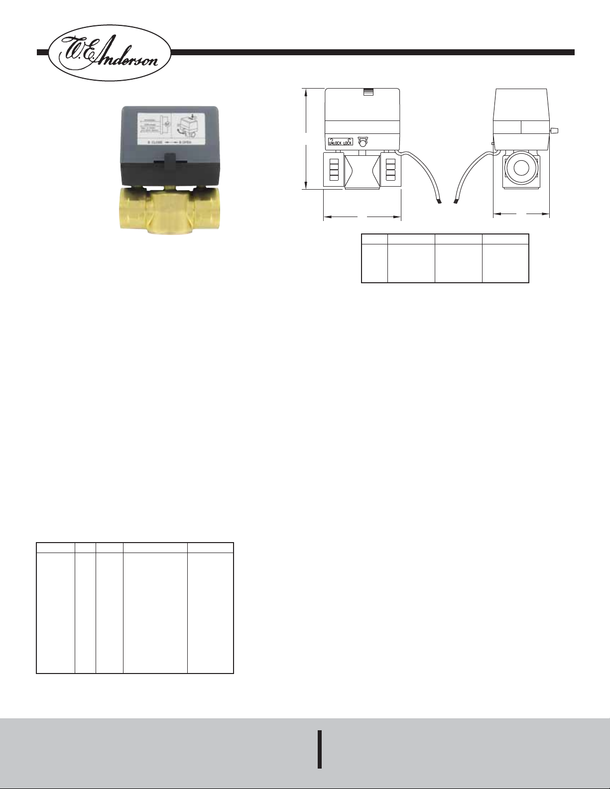
Specifications - Installation and Operating Instructions
A
B
A [in (mm)]
Size
4.53 (115)
1/2˝
4.53 (115)
3/4˝
4.61 (117)
1˝
5.16 (131)
1-1/4˝
SPECIFICATIONS
Service: Compatible fluids.
Body: 2-way, normally closed.
Line Size: 1/2˝ to 1-1/4˝.
End Connections: Female NPT (optional BSP, sweat connections).
Pressure Limits: Maximum: 300 psi (20.7 bar); Close-off: 43 psi (2.96
bar).
Temperature Limits: Ambient: 32 to 104°F (0 to 40°C); Process: 37 to
201°F (3 to 94°C).
Wetted Materials: Brass, stainless steel, NBR.
Flow Characteristic: Quick opening.
Input: Floating: 3-wire, Modulating: 0 to 10 VDC or 4 to 20 mA (24
VAC power only).
Power Requirements: 120 VAC or 24 VAC, ±10%, 50/60 Hz. (Optional
220 VAC).
Power Consumption: Floating: 2.5 VA; Modulating: 3.5 VA.
Electrical Connection: 18 AWG jacketed, 9˝ (228 mm) long.
Cycle Time: Opening time: 50 to 65 seconds.
Enclosure Rating: General purpose.
Housing Material: PVC and polycarbonate.
B [in (mm)]
3.15 (80)
3.50 (89)
3.66 (93)
4.13 (105)
C [in (mm)]
2.64 (67)
2.64 (67)
2.64 (67)
2.64 (67)
C
Model
ZV20212
ZV20214
ZV20224
ZV20312
ZV20314
ZV20324
ZV20412
ZV20414
ZV20424
ZV20512
ZV20514
ZV20524
Cv
3.8
3.8
3.8
3.8
3.8
3.8
8.0
8.0
8.0
11.7
11.7
11.7
Size
1/2˝
1/2˝
1/2˝
3/4˝
3/4˝
3/4˝
1˝
1˝
1˝
1-1/4˝
1-1/4˝
1-1/4˝
Supply Voltage
120 VAC
24 VAC
24 VAC
120 VAC
24 VAC
24 VAC
120 VAC
24 VAC
24 VAC
120 VAC
24 VAC
24 VAC
Input
Floating
Floating
Modulating
Floating
Floating
Modulating
Floating
Floating
Modulating
Floating
Floating
Modulating
W.E. ANDERSON DIV., DWYER
INSTRUMENTS, INC.
P.O. BOX 358 • MICHIGAN CITY, INDIANA 46361 U.S. A.
Phone: 219/879-8000 www.dwyer-inst.com
Fax: 219/872-9057 e-mail: info@dwyer-inst.com
Page 2
Instructions for Operation and Use
1. Assembly and disassembly of the actuator and valve body fit the
square axis of the valve body with the square hole in the actuator and
insert (make sure that another axis will not touch the actuator). Rotate
the actuator or valve body, make another axis of the valve body aim at
the corresponding hole in the actuator. Use a little force to press the
actuator. Turn the locking key clockwise to lock the actuator into place.
The assembly of the actuator and valve body is finished. When
disassembling, turn the locking key counterclockwise, and use a little
force to pull out the actuator in the opposite direction used during
assembly.
2. 2-way valves are installed as Figure 2 and 3 shows. For high building,
pressure–reducing valve should be installed on branch pipe at ground
floor.
3. Note: When the valve is mounted on a horizontal pipe, the angle must
be positioned less than 85° (see Figure 4). When the valve is mounted
on a vertical pipe, prevent from dripping.
4. Manual operating lever: The valve is unlocked when you press the
manual operating button. Moving the manual lever can make the valve
return. When releasing the button, the valve will be locked again
automatically.
5. When installing a 2-way valve, the flow direction is from end “B” to “A”.
For a normal-open valve, it is from end “A” to “B”. In both situations, the
valve closing direction is opposite.
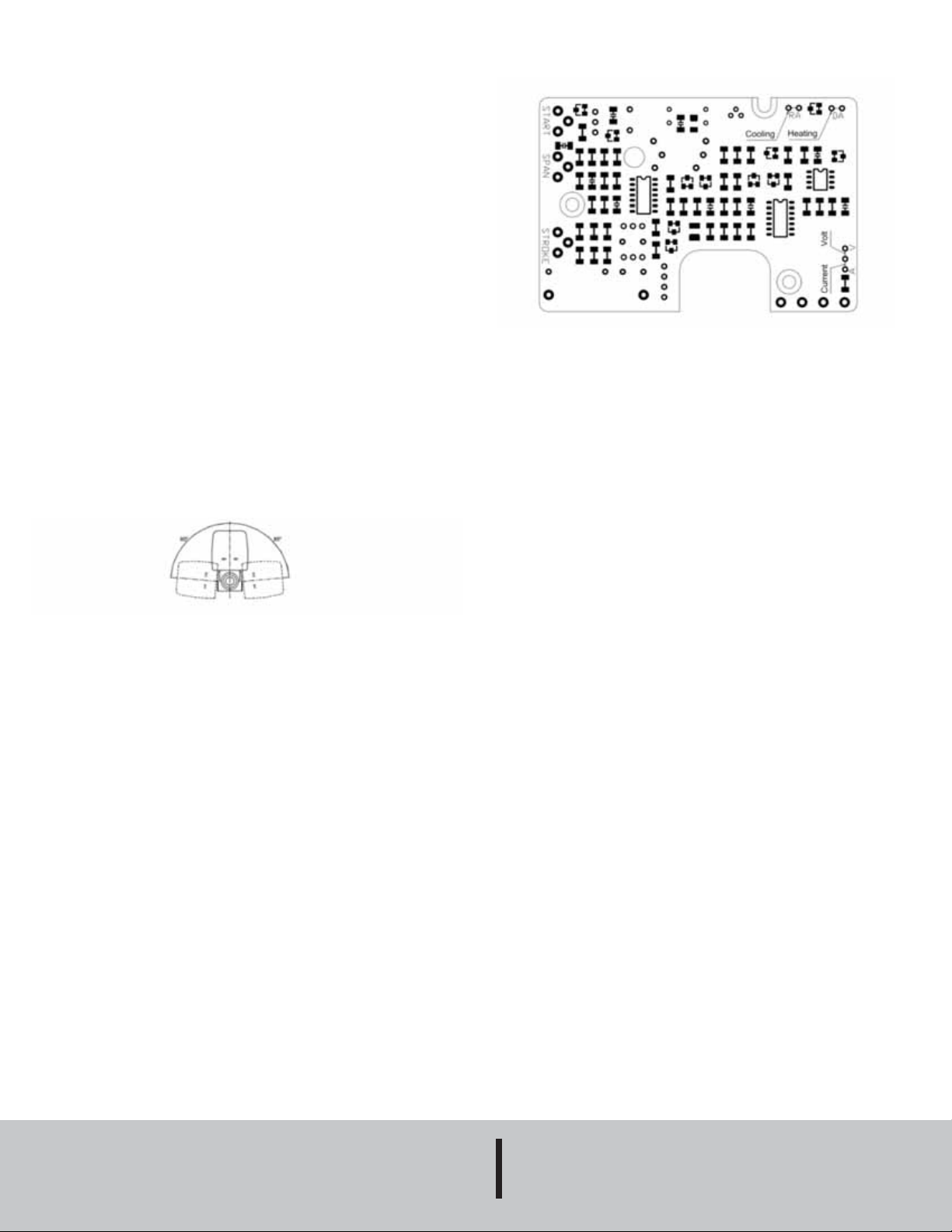
Electronic Card Setting Diagram
MAINTENANCE
Upon final installation of the Series ZV2 Two-Way Detachable Zone
Valves, no routine maintenance is required. A periodic check of the
system calibration is recommended. The Series ZV2 is not field
serviceable and should be returned if repair is needed (field repair
should not be attempted and may void warranty). Be sure to include a
brief description of the problem plus any relevant application notes.
Contact customer service to receive a return good authorization number
before shipping.
Fig. 4
©Copyright 2010 Dwyer Instruments, Inc. Printed in U.S.A. 3/10 FR # RB-443459-20 Rev. 2
W.E. ANDERSON DIV., DWYER
INSTRUMENTS, INC.
Phone: 219/879-8000 www.dwyer-inst.com
Fax: 219/872-9057 e-mail: info@dwyer-inst.com
P.O. BOX 358 • MICHIGAN CITY, INDIANA 46361 U.S. A.
 Loading...