

Page 1
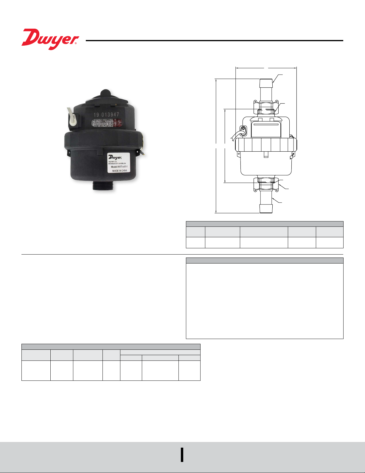
Series WVT Vertical Water Meter
L1
)
W
Specications - Installation and Operating Instructions
L
Bulletin F-WVT
D
D1
GASKET (X2)
NUT (X2)
The Series WVT Vertical Water Meter is a series of rotary piston water meters that
display total water usage. The piston displacement technology results in accurate and
reliable operation in either horizontal or vertical mounting. Polymer and stainless steel
construction provides high durability and environmental resistance at an economical
price. The optional pulse output can be used for ow verication and totalization.
Adapter couplings are included to convert BSPP threads on the meter to NPT.
MODEL CHART
Model Meter Size Coupling Size Output
WVT-A-01
WVT-A-02
WVT-A-01-1
WVT-A-02-1
3/4˝
1˝
3/4˝
1˝
1/2˝ NPT
3/4˝ NPT
1/2˝ NPT
3/4˝ NPT
GPM (Gallons Per Minute)
Min Flow Transitional Flow Max Flow
None
None
Pulse
Pulse
0.07
0.11
0.07
0.11
0.11
0.18
0.11
0.18
COUPLING (X2
DIMENSIONS CHART
Spud
Size
G3/4G14.53 (115)
SPECIFICATIONS
Service: Water.
Wetted Materials: ABS, POM, SS, Buna-N.
Flow Range: See model chart.
Accuracy: Nominal ow: ±2%; Transitional ow: ±5%.
Temperature Limit: 122°F (50°C).
Pressure Limit: 150 psi (1034 kPa).
Totalizing Display Maximum: 999,999.99 gallons.
Output Signal: Pulse output with frequency proportional to owrate.
Pulse Rate: 0.05 gal/pulse.
Electrical Rating: 0.01 A @ 24 VAC/DC.
Electrical Connections: 3.5mm2 stranded color-coded lead wires, 5´ (1.5 m)
length.
Mounting Orientation: Horizontal or vertical.
Weight: See dimension chart.
13.75
22
13.75
22
Length “L” in
(mm)
6.50 (165)
Length with NPT
Coupling “L1” in (mm)
8.23 (209)
10.16 (258)
Width “W”
In (mm)
3.78 (96)
4.17 (106)
Weight lb
(kg)
1.15 (0.52)
1.34 (0.6)
DWYER INSTRUMENTS, INC.
P.O. BOX 373 • MICHIGAN CITY, INDIANA 46360, U.S.A.
Phone: 219-879-8000
Fax: 219-872-9057
www.dwyer-inst.com
e-mail: [email protected]
Page 2
Installation Instructions
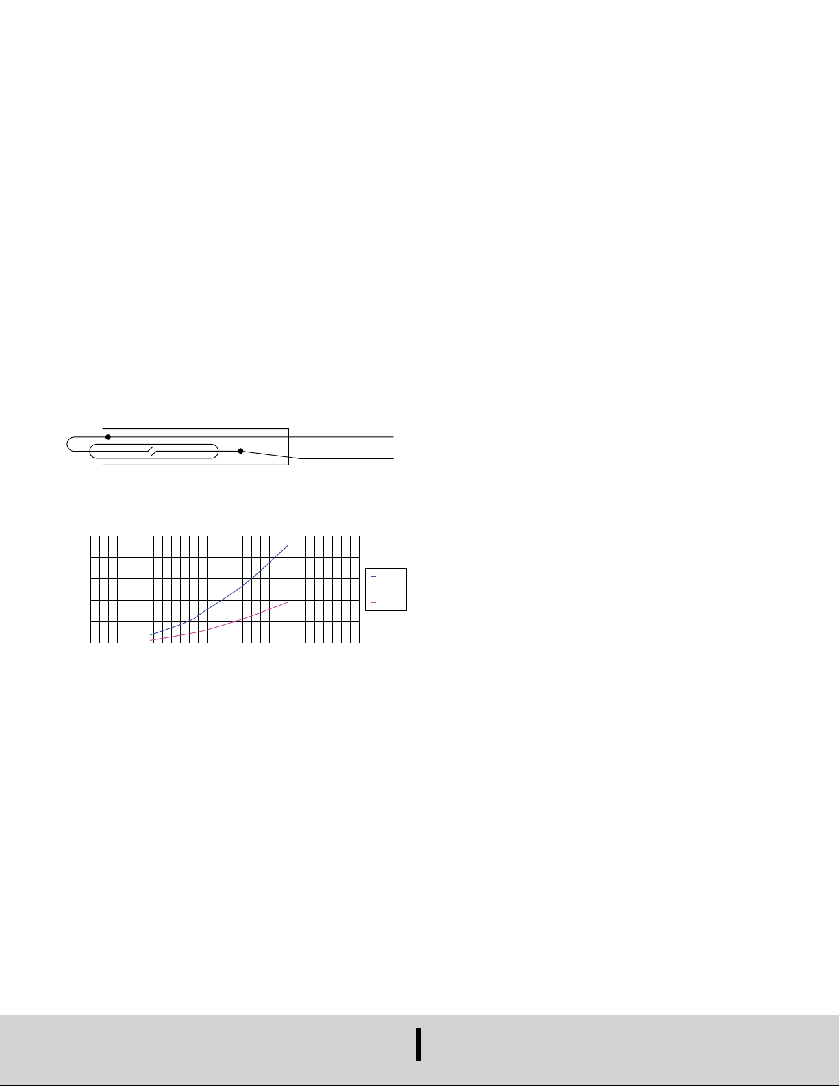
FLOW [GPM]
PRESSURE LOSS [kPa]
PRESSURE LOSS CURVE
BLACK - COMMON
1. Thoroughly ush the service line upstream of the meter to remove dirt and debris.
2. Remove thread protectors.
Note: To protect meter threads, store the meter with thread protectors in place.
3. If applicable, install NPT thread adapters to WVT. Insert the threaded coupler into
the nut with the coupler threads facing the nut wings. Place the gasket on the at
surface of the coupler inside the nut. Thread nut onto water meter. Do not
overtighten.
4. Set the meter in the line. Install in a vertical or horizontal face up orientation in a
location accessible for reading, service, and inspection. Install with the window
closer to the inlet side of the owmeter. The arrow adjacent to the window should
point opposite the direction of ow. For accurate readings, ensure the meter is
installed between straight pipes on the inlet and outlet side that are a minimum
length of 3 times the nominal pipe diameter.
5. Wrap the exposed meter threads with pipe thread tape. Install meter and tighten
connections.
6. Do not over-tighten connections; tighten only as required to seal.
7. With upstream shut-off valve only: Open shut-off valve slowly to remove air from
meter and service line. Open the water source slowly to allow entrapped air to
escape. Close the water source.
8. With both upstream and downstream shut-off valves installed:
Test the installation for leaks: Close the outlet (downstream) shutoff valve.
Open the inlet (upstream) shut-off slowly until meter is full of water. Open the outlet
(downstream) valve slowly until air is out of the meter and service line. Open the
water source slowly to allow entrapped air to escape. Close the water source.
Electrical Installation
MAINTENANCE/REPAIR
Upon nal installation of the Series WVT, no routine maintenance is required. The
Series WVT is not eld serviceable and it is not possible to repair the unit. Field repair
should not be attempted and may void warranty.
WARRANTY/RETURN
Refer to “Terms and Conditions of Sale” in our catalog and on our website. Contact
customer service to receive a Return Goods Authorization number before shipping the
product back for repair. Be sure to include a brief description of the problem plus any
additional application notes.
250
200
150
100
50
0
RED - NO
15 mm
12 mm
302520151050
DWYER INSTRUMENTS, INC.
P.O. BOX 373 • MICHIGAN CITY, INDIANA 46360, U.S.A.
Printed in U.S.A. 11/20 FR# 444567-00 Rev. 1©Copyright 2020 Dwyer Instruments, Inc.
Phone: 219-879-8000
Fax: 219-872-9057
www.dwyer-inst.com
e-mail: [email protected]
 Loading...