

Page 1
Bulletin W-WTP-W
Series WTP-W Wireless Wall Mount Temperature Sensors
Specifications - Installation and Operating Instructions
The Series WTP-W Wireless Wall Mount Temperature Sensors
allows flexibility in office buildings with cubicles or in hotel rooms.
Without any wires to limit the location of the sensor, it can be moved
quickly without any interruption in temperature measurement. Optional
temperature set point and manual override features allow users to adjust
temperatures to make the ambient conditions more comfortable.
A reliable 418 MHz signal can carry the measurements up to 100 feet
without a repeater. With the optional 900 MHz repeater, measurements
can be transmitted up to 1000 feet away.
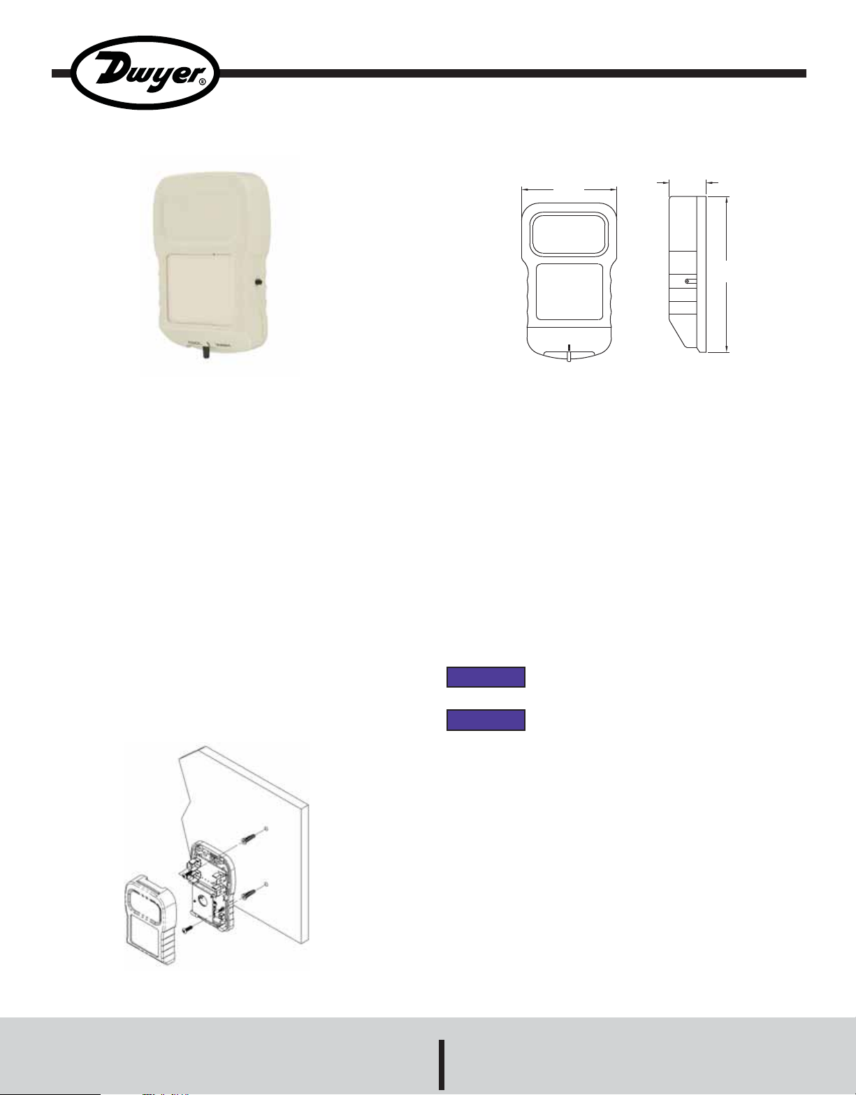
MOUNTING
Use the base plate to mark two holes on the surface that the sensor will
be mounted. Drill two 3/16˝ holes in the center of each marking. Insert
drywall anchor into each hole. Attach back plate to surface using the
provided #6 screws into anchors. Install batteries into battery clips while
observing the polarity marked on the circuit board. Attach cover and use
Allen wrench to tighten locking screw until it is flush with bottom of cover.
2-3/4
[69.85]
COOL WARM
SPECIFICATIONS
Temperature Range: -40 to 185°F (-40 to 85°C).
Accuracy: ±0.54°F (±0.3°C).
Temperature Limits: 32 to 140°F (0 to 60°C).
Humidity Limits: 5 to 95% RH non-condensing.
Power Requirements: 2 AA 3.6V lithium batteries.
Transmitter Interval Rate: Approximately 10-15 seconds.
Housing Material: ABS plastic.
Enclosure Rating: UL 94 V-0.
Antenna: 418 MHz - Built inside enclosure.
Weight: 0.25 lb (113 g).
FCC Approval: FCC ID# T4F061213RSO.
Agency Approvals: RoHS.
NOTICE
NOTICE
When inserting batteries, observe polarity
markings inside unit for proper operation.
It is best to train output modules before mounting
the transmitters.
1-1/16
[26.92]
4-1/2
[114.30]
Figure 1: Mounting Diagram
DWYER INSTRUMENTS, INC.
Phone: 219/879-8000 www.dwyer-inst.com
P.O. BOX 373 • MICHIGAN CITY, INDIANA 46361, U.S.A. Fax: 219/872-9057 e-mail: info@dwyer-inst.com
Page 2
Training Output Models
Temperature/Set Point Output Modules
• Attach desired output modules to receiver as described in output
module manual.
• Apply power to the receiver and output modules (LED on receiver
should be lit. LED on output module will flash and go out).
• Remove the lid of sensor and install the batteries (observe polarity).
LED located at the bottom right of the circuit board next to the set
point adjustment knob (if equipped) will flash every 10 seconds.
• Press and hold the plastic service button on the output module to be
programmed. At the same time, press for one second and release the
button on the sensor. When the LED on the output module lights,
release the service button. The LED on the output module will go out
after the button is released.
• Output module LED will flash when it receives data from sensor.
• If equipped, set point adjustment should be programmed to a WM-S
output module using the above steps except you will push the
override button on the sensor instead of the transmitter training button
(on sensors that are not ordered with external override buttons, the
override button is located inside the housing).
• The override button can be programmed in parallel with a previously
trained set point or temperature output module or using a separate
output module. See below section on training override output
modules in parallel or use same steps as training the set point
adjustment when using a separate output module.
• Close cover and mount the transmitter to location within 100 feet of
receiver.
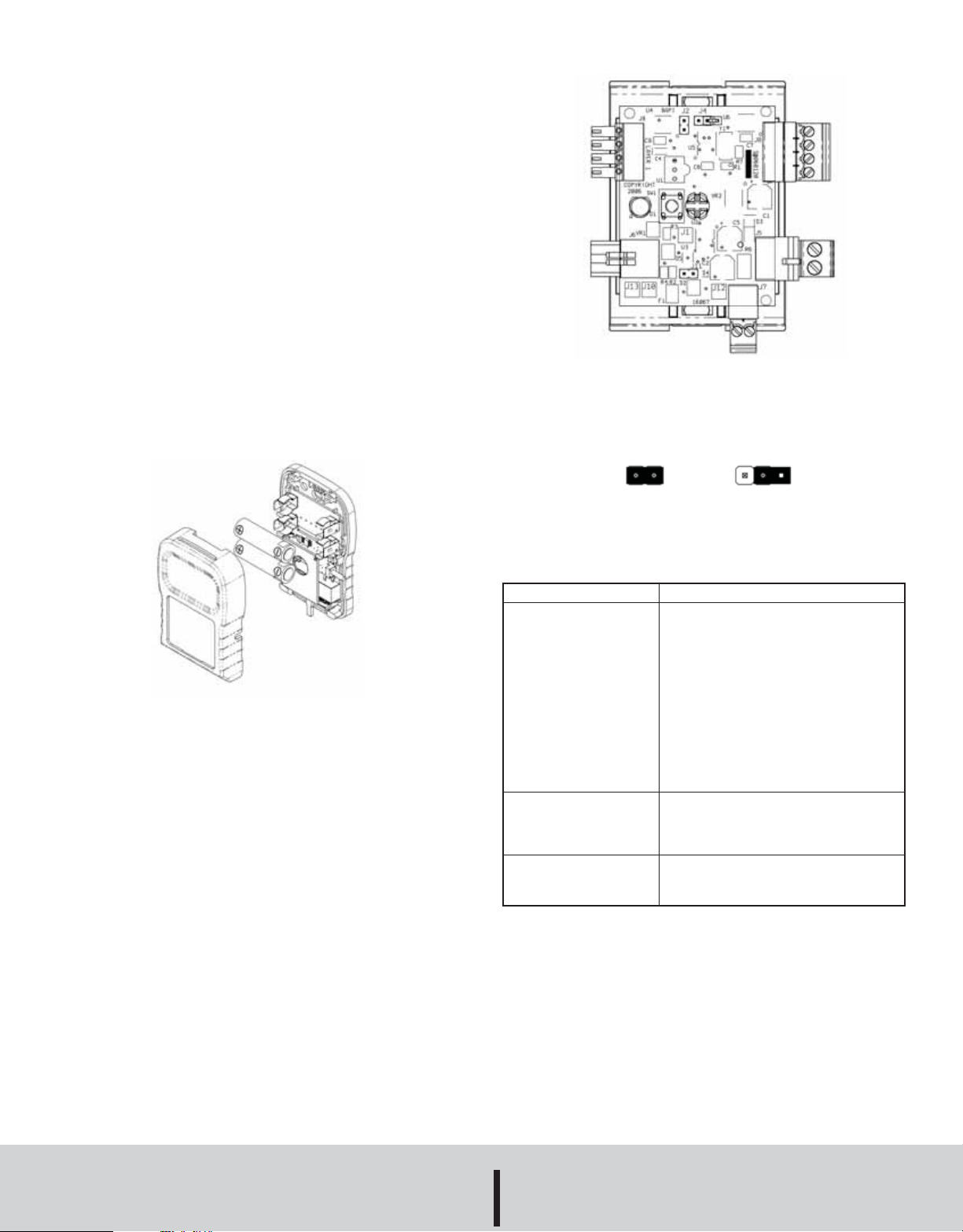
Figure 3: Output Module
Training Position Storage Position
Figure 4: J4 Jumper on Output Module
Figure 2: Polarity of Battery Installation
Override Output Module in Parallel to Temperature or Set Point
When override button is trained in parallel to the temperature or set point
output module, that output module will measure its lowest value for 5
seconds when the override button is pressed. Then, it will resume its
normal operation.
• If temperature or set point output module has not been trained, please
train that module before proceeding.
• Remove output module cover by squeezing the top and bottom of the
housing.
• Apply power to the receiver and output module (LED on receiver will
remain lit).
• Remove the cover from the sensor and insert the batteries (observe
polarity). LED located at the bottom right of the circuit board will
flash approximately every 10 seconds.
• On the output module, move the jumper labeled J4 to the training
position (see Figure 4).
• Press and hold the SW1 next to the LED on the output module.
• At the same time press for one second and release the override
button on the sensor. When the LED on the output module lights,
release the service button. The LED on the output module will go out
after the button is released.
• On the output module, move the jumper labeled J4 to the storage
position.
• Replace the cover on the output module.
• Mount the sensor within 100 feet of a repeater or receiver.
DIAGNOSTICS
Error
Temperature reading is
incorrect
Output module red LED
flashing rapidly
Temperature reading is
coming out of wrong
output module
MAINTENANCE, CLEANING AND REPAIR
After final installation of the unit, no routine maintenance is required. A
periodic check of the system calibration is recommended. The Series
WTP-W is not field serviceable and should be returned if repair is
needed (field repair should not be attempted and may void warranty). Be
sure to include a brief description of the problem plus any relevant
application notes. Contact customer service to receive a return goods
authorization number before shipping.
Required Action(s)
• Check wire from output modules to
controller for proper connections and
polarities.
• Check to see if the controller’s software
is configured correctly.
• Check transmitter to see if its LED
flashes every 10 seconds. If not, change
batteries.
• Check power to the receiver and output
module.
• Check output module LED. If blinking
fast, retrain output module.
• Check transmitter to see if its LED
flashes every 10 seconds. If not, change
batteries.
• Retrain output module.
• Retrain output module.
©Copyright 2009 Dwyer Instruments, Inc. Printed in U.S.A. 12/09 FR# R6-443760-00
DWYER INSTRUMENTS, INC.
Phone: 219/879-8000 www.dwyer-inst.com
P.O. BOX 373 • MICHIGAN CITY, INDIANA 46361, U.S.A. Fax: 219/872-9057 e-mail: info@dwyer-inst.com
 Loading...