

Page 1
Bulletin TE-WT2-10
5
-55/64
[
148.87]
3-15/16
[100.00]
3
/16
[
4.80]
45/64
[18.01]
1-31/32
[50.02]
BATTERY
COMPARTMENT
NEEDLE THERMOMETER
WT2-10
MODE
HOLD
MX/MI/AT
Model WT2-10 Needle Thermometer
Specifications - Installation and Operating Instructions
he Model WT2-10 Stainless Steel Needle Thermometer provides accurate
T
easurements for testing internal temperatures during food safety inspections. A
m
retractable penetration probe automatically shuts off the meter when closed, as
well as protects the user from the sharp tip while not in use. Additional features
include minimum and maximum readings, audible and visual alarms, and a
measurement hold function. Besides the probe temperature, the Model WT2-10
lso measures the ambient air temperature.
a
EATURES
F
• Contacted temperature measurement
• Air temperature measurement
• Hi/Lo alarm setting with audible sound
• Data hold/Maximum/Minimum functions
• Auto power off function
• Quick response and high accuracy
• Low battery indication
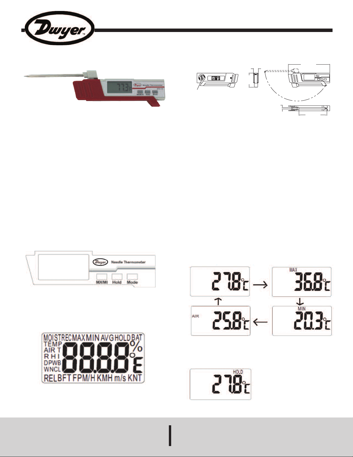
KEY FUNCTION
1. MX/MI: Alternates display between the probe, minimum, maximum and ambient
air temperatures.
2. Hold: Freezes current reading on the display and acts as the up button.
3. Mode: Toggles the temperature unit and acts as the down button.
OPERATION
1. Power On/Off
With meter off, extend the probe away from the body to turn on the meter with a
beep sound. To turn the meter off, fold the probe completely against the meter
body. The meter will also turn off automatically after 10 minutes if no action is
taken.
SPECIFICATIONS
Range: -40 to 302°F (-40 to 150°C).
ccuracy: ±1°F @ -4 to 248°F (1°C @ -19.99 to 119.9°C); ±2°F/C (others).
A
emperature Limits: Ambient: -4 to 122°F (-20 to 50°C).
T
isplay: 4 digit LCD.
D
Resolution: 0.1° F/C.
Power Requirements: One 3V CR-2032 lithium battery.
Sensor: Thermistor.
Probe Diameter: 0.19˝ (4.8 mm).
nclosure Rating: IP54.
E
eight: 3.2 oz (91 g).
W
gency Approvals: CE.
A
2. Maximum and Minimum Mode
The meter will cycle between probe temperature, MAX, MIN and air temperature
on the LCD. When first turning on the meter, the probe temperature will be
displayed. With meter on, press the MX/MI button and the “MAX” icon will appear
on the display with the maximum temperature reading. Press the MX/MI button
again, the “MIN” icon will appear on the display with the minimum temperature
reading. After pressing the “MX/MI” button a third time, “AIR” icon will appear on
the display along with the ambient air temperature reading.
3. Data Hold
1. Press the HOLD button to freeze the displayed reading. The ‘HOLD’ icon and
the held reading will appear on the display.
2. Press the HOLD button again, and the meter will return to normal operation.
DWYER INSTRUMENTS, INC.
P.O. BOX 373 • MICHIGAN CITY, INDIANA 46360, U.S.A. Fax: 219/872-9057 e-mail: info@dwyer-inst.com
Phone: 219/879-8000 www.dwyer-inst.com
Page 2
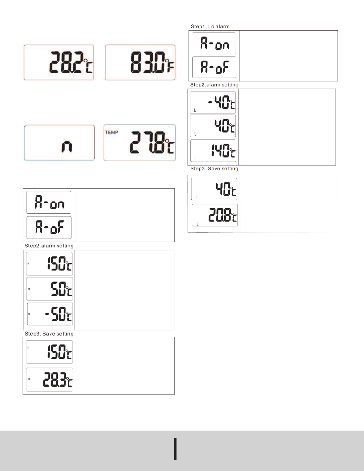
4. Temperature Unit Selection (°C/°F )
With the meter on, press and hold the MODE button for more than 2 seconds to select
the desired units; the display will indicate the changes (°C/°F).
. Auto Power OFF
5
he meter will shut off automatically after approximately 10 minutes if no action is
T
taken. To disable auto power off, when meter is off press HOLD button and extend the
probe away from the body of the meter, “n” icon will appear on the LCD, and release
HOLD button. The meter will return to normal measurement and “TEMP” icon will
ppear with the temperature reading.
a
6. Setting Mode
Hi Lo Alarm
Step1. Hi alarm
With meter on, press MX/MI and HOLD buttons at the same
time to enter Hi alarm setting. A blinking “A-on” icon will
ppear on the LCD.
a
Press MODE button to select High alarm “A-on” or “A-oF”.
(a) If “A-on” is selected, press MX/MI button to save and
ove to step 2 for High temp. alarm setting.
m
(b) If “A-oF” is selected, long press MX/MI button to save.
With meter on, press MX/MI and MODE buttons
t the same time to enter Low alarm setting. A blinking “A-
a
on” icon will appear on the LCD.
Press MODE button to select Hi alarm “A-on” or “A-oF”.
a) If “A-on” is selected, press MX/MI button to save and
(
move to step 2 for Low temp. alarm setting.
(b) If “A-oF” is selected, press MX/MI button to save and
hen the meter will return to normal measurement.
t
After Lo alarm is set, L-40°C will appear on the LCD and
igit “1” will start blinking, press Hold (Up)/ Mode (Down)
d
button to select the desired digit (“1”, “0”, “-”).
Note: The temperature range is -40~150°C (-40~302°F),
o the meter will not function if Hi/Lo alarm setting
s
exceed the temperature range
ress MX/MI button to save the Low temp. alarm setting
P
and “L” icon will appear on the left of the current temp.
reading.
After Hi alarm is set, H150°C will appear on the LCD and
digit “1” will start blinking, press Hold (Up)/ Mode (Down)
button to select the desired digit (“1”, “0”, “-”).
Note: The temperature range is -40~150°F (-40~302°F),
so the meter will not function if Hi/Lo alarm setting
exceed the temperature range.
Long press MX/MI button to save the High temp. alarm
setting and “H” icon will appear on the left of the current
temp. reading.
7. Stop Beeper Temporarily
If the temperature exceeds the Hi/Lo alarm setting, the meter will give an audible
sound, shortly press MODE button to stop the beep sound, then the meter is ready to
take the next measurement.
8. Battery Replacement
Use a coin to remove the battery compartment cover on the rear of the meter. Replace
the CR-2032 lithium battery; install the new battery face up (+) in the battery
compartment.
Disposal: Follow the valid legal stipulations in respect of the disposal of the device at
the end of its life cycle.
MAINTENANCE/REPAIR
Upon final installation of the WT2-10, no routine maintenance is required. The Series
WT2-10 is not field serviceable and should be returned if repair is needed. Field repair
should not be attempted and may void warranty.
WARRANTY/RETURN
Refer to “Terms and Conditions of Sales” in our catalog and on our website. Contact
customer service to receive a Return Goods Authorization number before shipping the
product back for repair. Be sure to include a brief description of the problem plus any
additional application notes.
©Copyright 2012 Dwyer Instruments, Inc. Printed in U.S.A. 8/12 FR# R6-443999-00
DWYER INSTRUMENTS, INC.
Phone: 219/879-8000 www.dwyer-inst.com
P.O. BOX 373 • MICHIGAN CITY, INDIANA 46360, U.S.A. Fax: 219/872-9057 e-mail: info@dwyer-inst.com
 Loading...