

Page 1
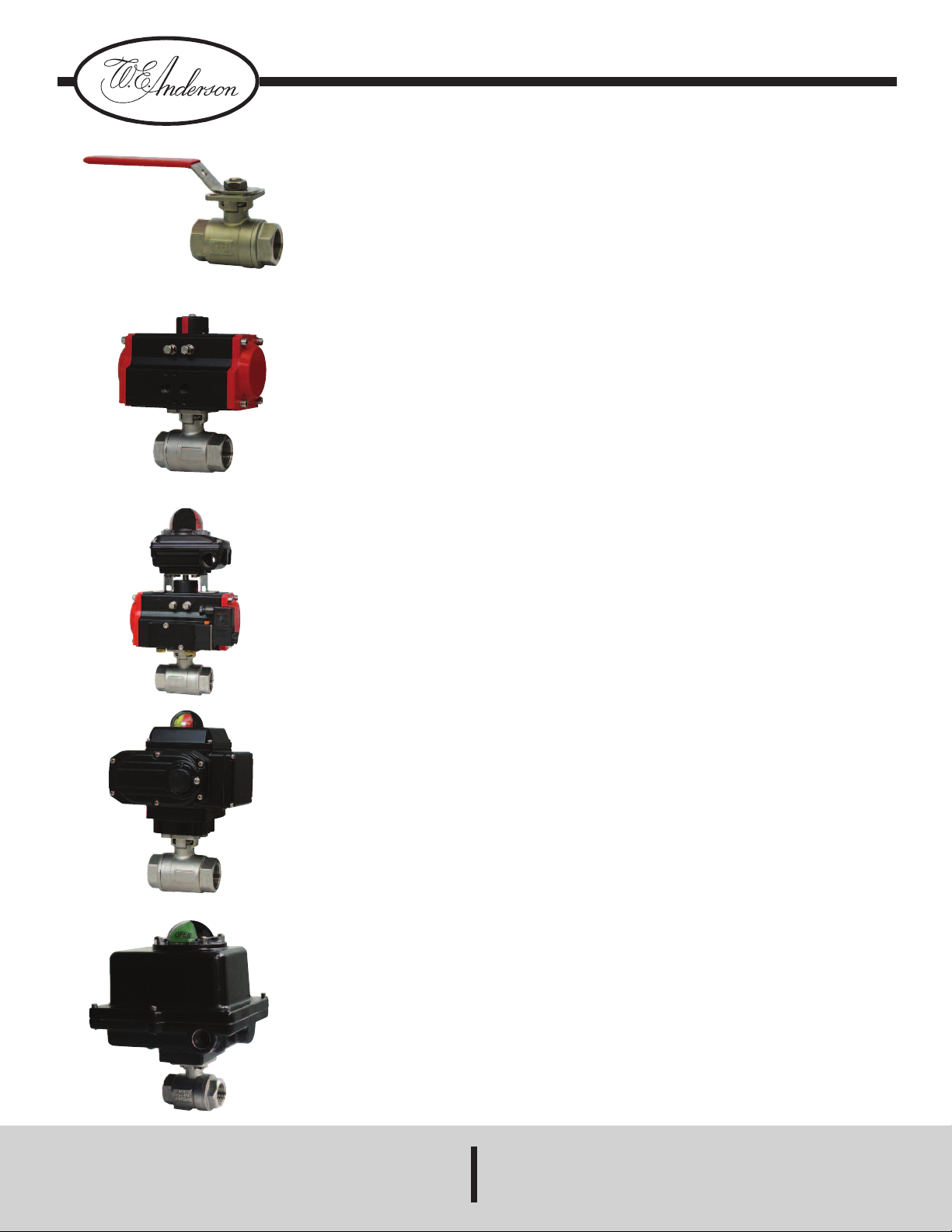
Series WE01 Two Way Stainless Steel Ball Valve
T
M
Specifications - Installation and Operating Instructions
Bulletin V-WE01
E01-EHD00
W
WE01-EDA02
WE01-EDA02-AA05
The Series WE01 incorporates a full
port two piece SS ball valve for great
flow rates with minimal pressure drop.
he valve features a blowout proof stem
T
or added safety, reinforced PTFE seats
f
nd seals for longer life, and a 316 SS
a
ASTM CF8M) ball for better
(
performance. Actuators are direct
mounted creating a compact assembly
for tight spaces. Limit switches are able
o be mounted directly to the valves
t
llowing for remote position indication.
a
The WE01 series can be configured
with either an electric or pneumatic
actuator. Electric actuators are available
in weatherproof or explosion-proof, a
variety of supply voltages and two-
osition or modulating control. Two-
p
osition actuators use the supply
p
oltage to drive the valve open or close,
v
hile the modulating actuator accepts a
w
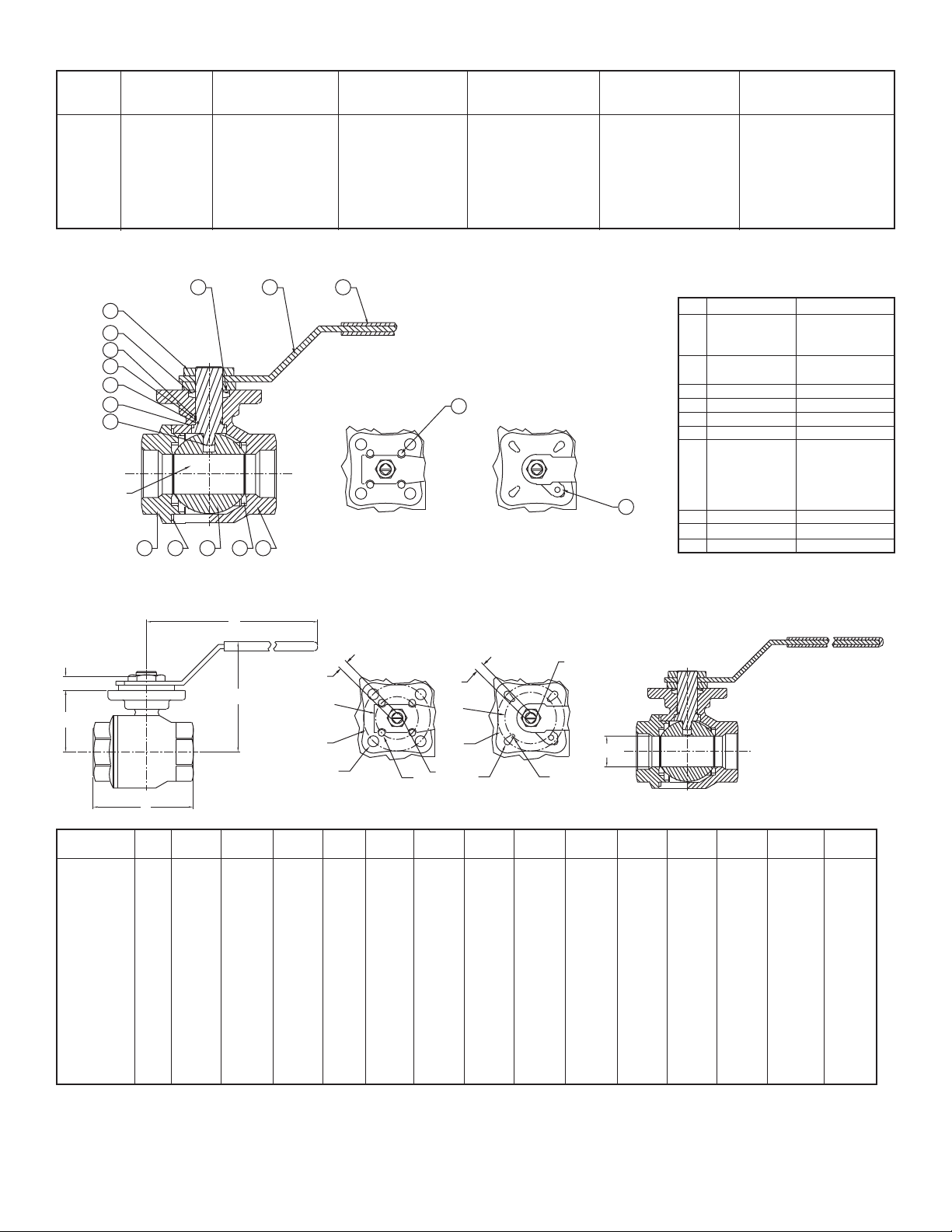
PECIFICATIONS
S
ALVE
V
ervice: Compatible liquids and gases.
S
Body: 2-piece.
Line Sizes: 1/2 to 3˝.
End Connections: Female NPT.
Pressure Limits: 20˝ Hg to 1000psi
( -0.7 to 69 bar).
Wetted Materials:
Body and Ball: 316 SS (CF8M);
Stem: 316SS;
Seat: RTFE/PTFE;
Seal, Washer and Packing: PTFE.
Temperature Limits: -20 to 392°F (-29
to 200°C).
Other Materials:
O-ring: Fluoroelastomer;
Handle: 304 SS;
Washer: 301 SS;
Stem Nut, Locking Device,
Gland Ring: 304SS;
Handle Sleeve: PVC.
4 to 20 mA input for valve positioning.
Actuators feature thermal overload
protection and permanently lubricated
ear train.
g
he pneumatic double acting actuator
T
ses an air supply to drive the valve
u
open and closed. The actuator has two
supply ports with one driving the valve
open and the other driving the valve
losed. Spring return pneumatic
c
ctuators use the air supply to open the
a
alve and internally loaded springs
v
return the valve to the closed position.
Also available is the SN solenoid valve
to electrically switch the air supply
pressure between the air supply ports
for opening and closing the valve.
ctuators are constructed of anodized
A
nd epoxy coated aluminum for years of
a
orrosion free service.
c
lectric “TD” and “MD” Series
E
ower Requirements: 110 VAC,
P
20 VAC, 24 VAC or 24 VDC (MD
2
models not available in 24 VDC).
Power Consumption: See page 8.
Cycle Time (per 90°):
TD01 4 s;
MD01: 10 s;
TD02 and MD02: 20 s;
TD03 and MD03: 30 s.
Duty Rating: 85%.
Enclosure Rating: NEMA 4X (IP67).
Housing Material: Powder coated
aluminum.
Temperature Limits: -22 to 140°F
(-30 to 60°C).
Electrical Connection: 1/2˝ female
NPT.
Modulating Input: 4 to 20 mA.
Standard Features: Manual override,
position indicator, and TD models come
with two limit switches.
WE01-ETD01-A
WE01-ETI02-A
W.E. ANDERSON,
A DIV. OF DWYER INSTRUMENTS, INC.
P.O. BOX 373 • MICHIGAN CITY, INDIANA 46360 U. S. A.
ACTUATORS
Pneumatic “DA” and “SR” Series
Type: DA series is double acting and
SR series is spring return (rack and
pinion).
Normal Supply Pressure:
DA: 40 to 115 psi (2.7 to 7.9 bar);
SR: 80 psi (5.5 bar).
Maximum Supply Pressure: 120 psi
(8.6 bar).
Air Connections:
DA01: 1/8˝ female NPT;
DA02 to DA05: 1/4˝ female NPT;
SR02 to SR07: 1/4˝ female NPT.
Housing Material: Anodized aluminum
body and epoxy coated aluminum
end caps.
Temperature Limits: -40 to 176°F (-40
to 80°C).
Accessory Mounting: NAMUR
standard.
Electric “TI” and “MI” Series
Power Requirements: 110 VAC,
220 VAC, 24 VAC or 24 VDC.
Power Consumption: See page 8.
Cycle Time (per 90°):
TI01 and MI01: 2.5 s;
TI02 and MI02: 5 s;
TI03 and MI03: 5 s;
TI04 and MI04: 10 s;
TI05 and MI06: 15 s.
Duty Rating:
Two-Position:
TI01-TI06: 25%.
Modulating:
MI01-MI06: 75%.
Enclosure Rating: NEMA 7.
Housing Material: Powder coated
aluminum.
Temperature Limits: -40 to 140°F
(-40 to 60°C).
Electrical Connection: 1/2˝ female
NPT.
Modulating Input: 4 to 20 mA.
Standard Features: Position indicator
and two limit switches.
Phone: 219/879-8000 www.dwyer-inst.com
Fax: 219/872-9057 e-mail: info@dwyermail.com
Page 2
PO
2-1/2˝ - 3˝
1/4˝ - 2˝
14
13
1
4
3
5
2
VENTED BALL
6
7
8
9
10
1
1
12
1
7
1
5
1
6
H1
H2
H
W
L
1/4˝ - 2˝
ØRb
ØRa
Ø02
Ø01
S
M1
M1
ØRb
ØRa
Ø02
Ø01
S
2-1/2˝ - 3˝
ØA
V
PU
LA
R
M
O
D
ELS
EMA 4X
EMA 4X Two-
N
Si
z
e
1
/
2
˝
3
/
4
˝
1
˝
1
-
1
/
4
1
-
1
/
2
2
˝
2
-
1
/
2
3
˝
A
L
VE
B
Cv
(gal/min)
36.64
7.69
6
10.27
1
˝
˝
˝
I
LL
84.73
1
66.62
2
485.3
791.57
1151.95
O
F
M
A
TER
I
A
LS
Hand Operated
Model
WE01-CHD00
E01-DHD00
W
E01-EHD00
W
E01-FHD00
W
E01-GHD00
W
WE01-HHD00
WE01-IHD00
WE01-JHD00
Double Acting
Pneumatic Model
WE01-CDA01
E01-DDA01
W
E01-EDA02
W
E01-FDA02
W
E01-GDA03
W
WE01-HDA03
WE01-IDA04
WE01-JDA05
Spring Return
Pneumatic Model
WE01-CSR02
E01-DSR02
W
E01-ESR03
W
E01-FSR03
W
E01-GSR04
W
WE01-HSR05
WE01-ISR07
WE01-JSR07
Position Electric
(110 VAC) Model
WE01-CTD01-A
E01-DTD01-A
W
E01-ETD01-A
W
E01-FTD01-A
W
E01-GTD02-A
W
WE01-HTD02-A
WE01-ITD03-A
WE01-JTD03-A
I
t
e
m
1
2
3
4
5
6
7
8
9
1
0
11
1
2
1
3
1
4
1
5
1
6
1
7
Description
Body
Cap
Ball
all Seat
B
oint Gasket
J
tem
S
Thrust Washer
O-Ring
Stem Packing
Stem Ring
elleville Washer
B
tem Nut
S
topper
S
Stopper Pin
Handle
Handle Cover
Lock Washer
N
Modulating Electric
(110 VAC) Model
WE01-CMD01-A
E01-DMD01-A
W
E01-EMD01-A
W
E01-FMD01-A
W
E01-GMD01-A
W
WE01-HMD02-A
WE01-IMD03-A
WE01-JMD03-A
Material
ASTM A351-CF8M
TFE
P
ISI 316
A
PTFE
Fluoroelastomer
PTFE
ISI 304
A
AISI 430
PVC
AISI 304
VA
LVE D
IM
Model
Number
WE01-CHD00
WE01-DHD00
WE01-EHD00
WE01-FHD00
WE01-GHD00
WE01-HHD00
WE01-IHD00
WE01-JHD00
EN
SIO
N
A
L D
R
AWIN
G
H
in(mm)
2-29/64˝
(62)
2-9/16˝
(65)
3˝
(76)
3-7/32˝
(81.5)
4-1/16˝
(103)
4-25/64˝
(111.5)
5-35/64˝
(141)
5-29/32˝
(150)
L
in(mm)
2-9/32˝
(58)
2-37/64˝
(65.6)
3-7/64˝
(78.7)
3-35/64˝
(90)
4-1/8˝
(105)
4-7/8˝
(124)
5-3/4˝
(146.2)
6-7/16˝
(163.7)
S
in(mm)
23/64˝
(9)
23/64˝
(9)
7/16˝
(11)
7/16˝
(11)
9/16˝
(14)
9/16˝
(14)
43/64˝
(17)
43/64˝
(17)
Page 2
ØRb
in(mm)
7/64˝
(2.75)
7/64˝
(2.75)
9/64˝
(3.5)
9/64˝
(3.5)
3/16˝
(4.5)
3/16˝
(4.5)
7/32˝
(5.5)
7/32˝
(5.5)
ISO
F03/04
F03/04
F04/05
F04/05
F05/07
F05/07
F07/10
F07/10
ØRa
in(mm)
7/64˝
(2.75)
7/64˝
(2.75)
7/64˝
(2.75)
7/64˝
(2.75)
9/64˝
(3.5)
9/64˝
(3.5)
3/16˝
(4.5)
3/16˝
(4.5)
ØD2
in(mm)
1-21/32˝
(42)
1-21/32˝
(42)
1-31/32˝
(50)
1-31/32˝
(50)
2-3/4˝
(70)
2-3/4˝
(70)
2-3/4˝
(102)
2-3/4˝
(102)
ØD1
in(mm)
1-27/64˝
(36)
1-27/64˝
(36)
1-21/32˝
(42)
1-21/32˝
(42)
1-31/32˝
(50)
1-31/32˝
(50)
1-31/32˝
(70)
1-31/32˝
(70)
ØA
in(mm)
Size
19/32˝
1/2˝
(15)
51/64˝
3/4˝
(20)
63/64˝
1˝
(25)
1-17/64˝
1-1/4˝
1-1/2˝
2˝
2-1/2˝
3˝
(32)
1-1/2˝
(38)
1-31/32˝
(50)
2-31/64˝
(63)
3˝
(76)
H1
in(mm)
5/16˝
(8)
23/64˝
(9)
7/16˝
(11)
7/16˝
(11)
29/64˝
(14)
29/64˝
(14)
13/16˝
(20.5)
13/16˝
(20.5)
H2
in(mm)
1-27/64˝
(36.4)
1-35/64˝
(39.2)
1-59/64˝
(48.7)
2-1/8˝
(54.2)
2-19/32˝
(65.7)
3˝
(75.5)
3-39/64˝
(91.5)
3-31/32˝
(100.75)
W
in(mm)
4-15/32˝
(113.5)
4-15/32˝
(113.5)
5-1/2˝
(140)
5-1/2˝
(140)
6-3/4˝
(172)
6-3/4˝
(172)
6-3/4˝
(172)
6-3/4˝
(172)
M1
M12x1.25
M12x1.25
M14x1.5
M14x1.5
M18x1.5
M18x1.5
M22x1.5
M22x1.5
Cv
(gal/min)
36.64
67.69
110.27
184.73
266.62
485.3
791.57
1151.95
Page 3
A
E
F
D
NPT
B
C
W/ NEMA 4X ELECTRIC ACTUATOR
E
W/ PNEUMATIC ACTUATOR
C
F
B
NPT
D
C
W/ EXPLOSION-PROOF ELECTRIC ACTUATOR
B
NPT
D
E
F
U
T
O
M
A
TED
V
A
L
VE
D
R
AW
I
N
G
S
D
oubl
e
A
c
t
i
ng
Pne
um
a
t
i
c
A
c
t
ua
t
or
3
/
4
˝
1
N
B
C
D
E
F
Spr
N
B
C
D
E
F
PT
PT
i
ng
1
/
2
˝
4
-
4
-
5
/
1
1
6
.
2
-
3
/
6
0
.
5
2
-
1
/
5
8
m
4
-
5
/
1
1
6
1
-
3
/
3
6
.
5
R
e
1
/
2
˝
5
-
1
/
1
2
8
2
-
3
/
7
1
m
2
-
1
/
5
8
m
5
-
3
/
1
4
5
1
-
5
/
4
1
m
3
8
˝
11
9
4
m
m
2
-
3
8
˝
6
0
.
m
m
2
-
5
4
˝
6
5
.
m
4
-
5
8
˝
11
6
m
m
1
-
3
8
˝
3
6
.
m
m
t
ur
n
Pne
um
3
/
4
5
-
8
.
4
4
4
8
1
˝
1
2
8
4
m
m
2
-
3
˝
7
1
mm
m
2
-
5
˝
6
5
.
m
5
-
3
˝
1
4
5
m
m
1
-
5
˝
4
1
mm
m
/
4
.
2
/
8
5
mm
/
8
6
mm
/
8
mm
/
8
5
mm
˝
/
8
.
/
4
/
8
6
/
4
mm
/
8
˝
mm
˝
˝
˝
˝
a
˝
4
mm
˝
˝
mm
˝
˝
˝
5
-
1
4
2
-
7
1
3
-
7
8
5
-
1
4
1
-
4
1
t
i
c
A
c
t
1
˝
6
-
1
5
3
-
8
2
3
-
7
8
6
-
1
6
1
-
4
6
1
/
0
3
/
mm
1
/
.
7
3
/
5
5
/
mm
ua
1
8
1
mm
1
.
7
5
9
3
mm
2
˝
.
7
4
˝
8
˝
mm
4
˝
mm
8
˝
t
/
4
.
7
/
4
/
8
mm
/
8
mm
/
4
mm
or
˝
mm
˝
˝
˝
˝
1
-
1
/
4
˝
1
-
1
/
2
˝
2
5
-
3
/
4
˝
6
-
.
2
4
˝
2
˝
4
˝
mm
8
˝
4
˝
8
˝
.
2
4
˝
2
˝
8
˝
mm
4
˝
mm
mm
7
1
7
3
3
-
1
8
2
mm
4
-
1
1
0
5
6
-
5
1
6
9
1
-
3
4
6
mm
1
-
1
7
-
1
1
8
3
-
3
9
4
4
-
1
1
0
7
-
7
2
0
2
˝
5
2
1
4
6
2
-
3
/
7
1
mm
3
-
1
/
9
0
mm
5
-
3
/
1
4
5
1
-
5
/
4
1
mm
1
-
1
/
6
-
3
/
1
6
2
3
-
1
/
8
2
mm
3
-
1
/
9
0
mm
6
-
5
/
1
6
9
1
-
3
/
4
6
mm
/
8
.
7
/
4
/
8
mm
/
8
mm
/
4
/
2
/
4
5
.
/
4
mm
/
8
5
mm
/
8
1
mm
mm
˝
mm
˝
˝
˝
˝
˝
˝
7
˝
˝
˝
mm
˝
7
-
1
8
3
-
8
2
4
-
1
2
6
-
1
6
1
-
4
6
2
˝
8
˝
2
0
4
˝
1
0
4
-
1
2
8
-
2
0
2
-
5
5
1
/
3
1
/
mm
7
/
4
5
/
9
3
/
mm
3
1
7
/
4
1
/
9
1
/
mm
4
˝
.
5
4
˝
8
˝
mm
8
˝
mm
4
˝
.
5
mm
8
˝
mm
4
˝
mm
8
˝
mm
mm
2
-
1
/
2
˝
3
/
8
.
5
/
4
/
4
.
2
/
8
mm
/
2
/
8
.
5
/
4
mm
/
4
.
2
7
/
mm
/
2
˝
mm
˝
˝
mm
˝
˝
˝
mm
˝
˝
mm
8
˝
˝
˝
9
˝
2
2
8
.
8
mm
4
˝
1
0
1
mm
6
-
1
/
2
˝
1
6
3
.
7
mm
8
-
1
/
4
˝
2
0
9
mm
2
-
1
/
8
˝
5
5
mm
3
˝
1
0
˝
2
5
3
.
8
mm
4
-
3
/
4
˝
1
2
2
mm
6
-
1
/
2
˝
1
6
3
.
7
mm
1
0
-
7
/
8
˝
2
7
5
mm
2
-
1
/
2
˝
6
4
mm
8
-
3
2
11
3
-
3
9
4
mm
5
-
3
1
4
6
7
-
7
2
0
1
2
˝
5
2
mm
2
-
1
9
-
5
2
4
4
4
-
3
1
2
2
5
-
3
1
4
6
1
0
-
2
7
5
2
-
1
6
4
mm
3
/
4
˝
1
N
PT
1
/2
˝
5
-
B
5
-1
/2
1
3
8
C
4
-1
/2
11
3
D
2
-1
/4
5
8
m
E
6
-1
/4
1
6
0
F
3
˝
7
7
m
NPT
1
/2
˝
B
7-3
/
1
1
9
9
9
-3/8
3
2
8
2
-1/4˝
5
8
m
8-1/2˝
2
1
6.7 mm
4-1
/
1
06.
mm
.
2
C
D
E
F
˝
.9
m
˝
m
m
˝
m
˝
m
m
m
6˝
˝
9
mm
m
˝
3 mm
m
3/
7-15/
202 mm
9-
328.
2-5/
65.
8-1/
216.
4-1/
106.
1
4
11
2
6
6
1
3
7
5
4
1
-
1
3
-
5
5
.
-
1
6
0
˝
7
mm
4˝
3/
6 mm
/
8
˝
.
7
/
2
˝
mm
/
8
˝
6
mm
/
4
˝
mm
16˝
8˝
9mm
8˝
2˝
7 mm
2˝
3 mm
mm
˝
6
˝
1
5
4
11
3
7
8
6
1
6
3
˝
7
7
1˝
8-
1/
211 mm
9-
3/
238.
3-1/
78.
8-1/
216.
4-
1/
106.
1
.
1
/
2
3
mm
1
/
8
.
7
1
/
4
0
mm
mm
4˝
8˝
9 mm
8˝
7 mm
2˝
7 mm
2˝
3 mm
2
mm
˝
˝
mm
˝
1
-
1
/
4
6
-
1
/
8
1
5
6
.
4
-
1
/
2
11
3
mm
3
-
1
/
2
9
0
mm
6
-
1
/
4
1
6
0
mm
3
˝
7
7
mm
1-1/
4˝
8-
1/
2˝
216.
5 mm
9-3/
8˝
238.
9 mm
3-1/
2˝
90 mm
8-1/
2˝
216.
7 mm
4-1/
2˝
106.
3 mm
7
˝
˝
mm
˝
˝
˝
1
-
1
/
2
˝
6
-
5
/
8
˝
1
6
8
.
2
4
-
1
/
2
˝
11
3
mm
4
-
1
/
8
˝
1
0
5
mm
6
-
1
/
4
˝
1
6
0
mm
3
˝
7
7
mm
1-1/
2˝
8-5/
8˝
219 mm
9-
3/
8˝
238.
9 mm
4-
1/
8˝
105 mm
8-1/
2˝
216.
7 mm
4-1/
2˝
106.
3 mm
mm
2
˝
7
˝
1
7
8
mm
4
-
1
/
2
˝
11
3
mm
4
-
7
/
8
˝
1
2
4
mm
6
-
1
/
4
˝
1
6
0
mm
3
˝
7
7
mm
2˝
10˝
255.
6 mm
8-1/
2˝
216 mm
4-7/
8˝
124 mm
8-1/
2˝
216.
7 mm
5-3/
8˝
136.
4 mm
2
-
1
/
2
8
-
5
/
8
2
1
7
.
4
-
3
/
4
1
2
1
mm
5
-
3
/
4
1
4
6
.
7
-
3
/
4
1
9
6
mm
3
-
7
/
8
9
8
mm
2-1/
10-3/
217.
8-
1/
216 mm
5-3/
146.
8-1/
216.
5-
3/
136.
˝
˝
5
mm
˝
˝
2
mm
˝
˝
2˝
5 mm
2˝
4˝
2 mm
2˝
7 mm
8˝
4 mm
3
˝
9
˝
2
2
6
.
8
mm
4
-
3
/
4
˝
1
2
1
mm
6
-
1
/
2
˝
1
4
6
.
2
mm
7
-
3
/
4
˝
1
9
6
mm
3
-
7
/
8
˝
9
8
mm
3˝
4˝
11˝
280.
8 mm
8-
1/
2˝
216 mm
6-1/
2˝
146.
2 mm
8-1/
2˝
216.
7 mm
5-3/
8˝
136.
4 mm
Page 3
Page 4

NEUMATIC ACTUATOR
P
ote: For optimal operation, pneumatic actuators should be run with a supply of
N
lean, lubricated air.
c
Spring Return Actuator Operation
Air to PORT 2 (the left hand port) causes the actuator to turn counter clockwise
(CCW). Loss of air to PORT 2 causes air to exhaust and the actuator turns
ockwise (CW). This is the FAIL CLOSE operation.
c
ouble Acting Actuators Operation
D
ir to PORT 2 (the left hand port) causes the actuator to turn counter clockwise
A
(CCW). Air to PORT 1 (the right hand port) causes the actuator to turn clockwise
(CW).
neumatic Actuator Maintenance
P
outine maintenance of pneumatic actuator:
R
Keep the air supply dry and clean
•
• Keep the actuator surface clean and free from dust
• Periodic checks should be done to make sure all fittings are tight
• Pneumatic actuators are supplied with lubrication to last the entire life span of the
actuator under normal operating conditions.
he outer surface of the pneumatic actuator should be clean to avoid friction or
T
orrosion. All fittings and connections should be tight to prevent leaks during
c
operation. Check the bolts mounting the valve to the actuator to make sure they
have not come loose during shipping or installation. Make sure the valve and
actuator are not rubbing or jamming against other components during operation.
The actuator should be inspected annually to make sure all fittings and bolts are
ight and nothing has come loose during operation.
t
isassembling Pneumatic Actuators
D
ARNING
W
emoved, and that the actuator has been disassembled from the valve.
r
1. Loosen the end cap fasteners (22) with a wrench (size varies depending on
actuator model). On the spring return actuator, alternate 3 to 5 turns on each
fastener until the springs are completely decompressed. Use caution when
removing the cap since the springs are under load until the fasteners are fully
extended.
2. Remove the pinion snap ring (10) with a lock ring tool. The indicator (7) may now
be removed.
3. Turn the pinion shaft (2) counter clockwise until the pistons are at the full end of
travel. Disengage the pistons (11) from the pinion. (NOTE: Low pressure air--3 to 5
psi MAXIMUM--might be required to force the pistons completely from the body.)
Note the position of the pistons before removing them from the actuator body.
4. Remove the pinion through the bottom of the actuator. The actuator is now
completely disassembled.
Pneumatic Actuators Bill of Materials
Before beginning disassembly, ensure that the air supply to the
ctuator has been disconnected, all accessories have been
a
I
n
s
p
e
c
t
i
o
n
I
t
e
m
Fa
i
l
ure
s
P
ne
um
a
t
a
c
t
ua
t
or w
ope
ra
t
e
P
ne
um
a
t
a
c
t
ua
t
or runs
s
l
ow
l
y
eassembling Pneumatic Actuators
R
WARNING
1. Apply a light film of grease to all O-rings and the pinion before replacing.
. Put the pinion (2) back through the actuator with the flats of the pinion shaft
2
unning parallel with the body.
r
. When reassembling the actuator, make sure that the piston racks are square to
3
the actuator body and returned to their original orientation. (NOTE: The normal
operation of all spring return pneumatic actuators is FAIL CLOSED. To change the
orientation to FAIL OPEN, rotate the racks 180º to create a reverse operation.
4. When replacing springs in a spring return actuator, ensure that the springs are
replaced in their identical position in the end cap from which they were removed.
(NOTE: In some circumstances, you might want to change the standard 80 pound
spring set to fit your application and available air pressure.
5. Seal the end caps with a petroleum lubricant and bolt to actuator body.
6. Check the seal of the actuator by covering seal areas (pinion, end caps) with
soapy water and using low pressure air to the actuator to ensure that no bubbles
are produced.
Part Number
1
2
3
4
5
6
7
8
9
10
11
12
13
14
15
16
17
18
19
20
21
22
23
24
25
26
27
1
.
C
h
e
i
c
i
c
on’
t
Quantity
1
1
1
1
1
1
1
1
1
1
1
1
1
4
2
2
2
2
5 to 12
2
1
1
8
2
2
2
2
c
t
h
e
c
o
i
l
s
o
l
e
n
o
i
2
.
T
h
e
b
e
c
a
u
s
3
.
T
h
e
a
c
t
u
a
t
o
s
m
a
s
h
e
4
.
T
h
e
b
e
c
a
u
s
a
n
d
m
o
1
.
T
h
e
i
n
s
u
f
f
i
c
2
.
A
r
e
o
c
o
n
s
u
m
t
h
e
a
c
t
u
3
.
T
h
e
u
n
d
e
r
s
i
Be sure the actuator surfaces are free of debris and scratches
before reassembling.
Part Name
Cylinder
Output Shaft
O-ring
Bearing
Adjusting Cam
Thrust Bearing
Bearing
O-ring
Bearing
Gasket
Damping Ring
Position Indicator
Screw
Position Indicating
Inserts
Piston
Guide Ring
O-ring
Guide Ring
Spring Assembly
O-ring
Left End Cap
Right End Cap
End Cap Bolt
O-ring
Gasket
Nut
Adjusting Bolt
s
k
t
h
e
s
o
l
e
n
o
i
d
v
b
u
r
n
t
o
d
s
p
o
o
l
a
c
t
u
a
t
o
e
o
f
d
e
p
n
e
u
m
a
r
i
s
d
i
s
t
d
.
p
n
e
u
m
a
e
o
f
l
o
w
i
s
t
u
r
e
.
a
i
r
s
u
p
p
i
e
n
t
.
t
h
e
r
p
n
i
n
g
t
h
e
a
t
o
r
t
o
p
n
e
u
m
a
z
e
d
f
o
r
a
u
t
o
r
i
s
t
h
?
r
w
i
l
l
n
o
t
m
b
r
i
s
i
n
t
h
e
t
i
c
l
i
n
e
t
o
o
r
t
e
d
o
r
t
i
c
l
i
n
e
i
s
t
e
m
p
e
r
a
l
y
p
r
e
s
s
u
e
u
m
a
t
i
c
d
a
i
r
r
e
q
u
i
r
o
p
e
r
a
t
e
?
t
i
c
a
c
t
u
a
t
t
h
e
a
p
p
l
i
c
C
o
r
r
e
c
t
i
v
e
A
c
t
i
o
l
v
e
.
I
s
1
.
R
e
p
l
e
o
v
e
g
e
a
r
s
.
t
h
e
f
r
o
z
e
n
t
u
r
e
s
r
e
i
s
e
v
i
c
e
s
e
d
f
o
r
o
r
i
s
a
t
i
o
n
.
Material
Extruded Aluminum Alloy
Stainless Steel
Fluorine Silicon Rubber
Nylon46
Stainless Steel
Nylon46
Nylon46
Fluorine Silicon Rubber
Nylon46
Stainless Steel
Stainless Steel
PPPP+30%GF
PPPP+30%GF
PPPP+30%GF
Casting Aluminum Alloy
Nylon46
Fluorine Silicon Rubber
Fluorine-Carbon Composite Material
Alloy Spring Steel
Fluorine Silicon Rubber
Casting Aluminum Alloy
Casting Aluminum Alloy
Stainless Steel
Fluorine Silicon Rubber
Stainless Steel
Stainless Steel
Stainless Steel
a
v
a
l
v
e
c
o
2
.
D
i
s
a
s
c
l
e
a
n
t
h
r
e
a
s
s
e
m
3
.
R
e
p
l
a
t
h
e
a
c
t
u
4
.
W
a
r
m
a
n
d
r
e
m
s
u
p
p
l
y
l
i
1
.
I
n
c
r
e
a
p
r
e
s
s
u
r
e
i
n
t
h
e
s
u
p
i
p
e
l
i
n
e
.
2
.
I
n
c
r
e
a
r
e
d
u
c
e
t
d
e
v
i
c
e
s
s
a
m
e
t
i
m
3
.
R
e
p
l
a
a
l
a
r
g
e
r
n
c
e
t
h
e
s
o
l
e
n
i
l
o
s
e
m
e
d
b
l
e
c
e
a
t
o
t
h
e
o
v
e
n
e
s
s
e
a
n
p
p
s
e
h
e
o
p
e
e
.
c
e
a
c
t
o
r
r
e
m
o
v
e
d
b
l
e
t
h
e
a
e
p
r
l
y
n
t
u
c
b
r
i
s
a
n
d
t
h
e
a
c
t
u
a
t
n
e
u
m
a
t
i
c
.
p
n
e
u
m
a
t
.
t
d
t
i
m
o
i
s
t
u
r
e
h
e
a
i
r
s
u
p
l
o
o
k
f
o
r
p
r
e
s
s
u
r
e
h
e
a
i
r
s
u
p
u
m
b
e
r
o
f
r
a
t
i
n
g
a
t
t
h
h
e
a
c
t
u
a
t
o
a
t
o
r
.
i
d
e
b
r
i
s
t
u
a
t
o
o
r
.
l
i
n
e
t
c
l
i
n
e
f
r
o
m
p
l
y
l
e
a
k
s
p
l
y
o
e
r
w
i
t
h
.
r
,
o
s
r
Page 4
Page 5

D
M
A
A
A
A
A
A
A
A
A
Spr
M
A
A
A
A
A
A
A
A
A
oubl
ode
C
C
C
C
C
C
C
C
C
i
ode
C
C
C
C
C
C
C
C
C
e
T-
D
T-
D
T
-
D
T-
D
T-
D
T-
D
T
-
D
T-
D
T-
D
ng
T-
SR
T
-
SR
T-
SR
T
-
SR
T-
SR
T
-
SR
T-SR
T
-SR
T
-SR
A
c
t
i
ng
A
c
t
ua
t
or
T
or
que
D
A
D
oubl
e
-
A
c
t
i
on O
ut
put
T
orque
(
l
b-
i
i
nd
n)
1
1
5
ps
ure
7
1
3
9
i
i
1
4
2
3
0
0
5
2
9
8
7
5
11
4
8
1
6
4
9
2
4
5
0
4
3
4
0
6
5
3
3
t
i
c
A
c
t
ua
t
or (
l
b-
i
n)
1
1
0
ps
i
1
1
5
ps
i
S
pri
ng T
orque
9
0
°
0
0
°
9
0
°
0
°
9
0
S
t
a
rt
E
nd
2
1
5
1
8
9
3
8
2
3
2
6
6
5
0
5
5
6
8
2
6
7
0
8
11
7
5
1
0
2
1
3
4
6
5
6
2
8
1
5
0
8
1
7
8
2
7
0
5
5
5
6
3
7
3
6
9
11
5
7
0
7
°
S
t
a
rt
E
nd
2
3
1
2
0
5
4
0
9
3
5
3
6
9
5
6
0
1
8
8
5
7
6
7
1
2
6
0
111
0
1
7
5
5
1
6
3
3
4
7
5
4
0
3
2
9
3
0
8
9
4
4
0
7
4
4
2
6
6
2
2
2
°
S
t
a
r
t
E
n
9
6
1
7
2
7
3
8
5
3
8
1
1
4
2
3
3
5
d
7
0
6
1
2
0
4
1
8
0
1
2
6
3
6
3
8
6
7
6
9
6
1
6
9
3
8
6
3
1
5
7
5
4
9
2
4
0
7
1
0
0
ps
i
1
1
0
1
2
3
2
5
9
4
5
6
7
5
4
9
9
0
1
4
1
2
1
1
3
7
4
5
6
3
c
t
i
ng P
°
8
5
5
0
1
8
5
5
7
0
9
9
1
ps
1
3
5
2
8
5
5
0
2
8
3
0
1
0
8
9
9
1
5
6
1
2
2
3
2
3
2
4
1
1
6
2
6
1
9
5
ne
um
a
A
i
r P
re
s
s
1
0
0
ps
i
9
0
°
0
°
E
nd
S
t
a
rt
1
6
4
1
8
9
2
8
0
3
3
6
4
8
1
5
7
5
6
0
9
7
2
7
8
8
3
1
0
3
3
1
2
9
1
4
1
7
2
3
3
2
8
0
4
3
1
7
3
9
9
2
4
8
4
6
0
5
3
A
i
r P
re
s
s
ure
l
4
0
ps
i
5
0
ps
i
6
0
ps
i
7
0
ps
i
8
0
ps
i
9
0
ps
A
0
1
4
9
6
1
7
4
8
6
9
A
0
2
1
0
4
1
3
0
1
5
A
0
3
1
8
2
A
0
4
A
0
5
A
0
6
A
0
7
A
0
8
A
0
9
R
e
t
l
0
2
0
3
0
4
0
5
0
6
0
7
0
8
0
9
1
0
2
3
0
2
3
3
9
6
4
5
6
7
7
8
4
5
1
1
4
9
7
1
2
2
5
3
2
ur
n
A
c
t
ua
Spr
i
ng
Q
ua
nt
i
t
y
1
0
1
0
1
0
1
0
1
0
1
0
1
0
1
0
1
0
5
2
8
2
7
4
7
7
4
5
3
9
5
5
9
4
0
9
8
5
1
0
5
6
1
2
6
8
8
t
7
7
1
2
2
4
5
1
6
3
3
7
9
or
T
or
que
7
0
ps
i
0
°
9
0
°
St
a
r
t
End
1
1
1
8
6
1
9
9
1
4
3
3
4
8
2
5
4
4
3
0
3
1
2
6
0
8
4
5
8
7
8
3
6
6
3
1
6
8
2
1
2
0
2
3
8
3
0
3
1
4
8
3
4
7
9
2
2
7
4
8
1
8
1
2
0
3
5
6
9
1
2
3
7
1
9
3
6
5
2
8
6
0
3
9
3
7
9
2
9
3
1
1
3
5
4
7
8
1
6
9
0
6
1
9
2
9
9
3
9
4
2
4
5
0
6
S
8
0
ps
i
0
°
9
0
°
St
a
End
r
t
1
3
7
1
1
2
2
4
5
1
8
9
4
2
4
3
3
0
5
2
9
4
1
1
7
5
0
5
9
9
9
9
4
8
7
4
2
0
5
1
6
5
8
2
4
3
8
6
2
6
0
4
6
3
3
3
7
1
3
3
i
1
1
0
2
3
3
4
1
1
6
7
9
8
9
1
1
2
7
7
1
9
0
1
3
3
6
7
5
0
6
9
R
S
i
ngl
e
A
9
0
ps
0
°
9
0
S
t
a
rt
E
1
6
3
1
3
2
9
1
2
3
4
9
9
4
0
6
2
8
5
1
8
9
1
7
4
1
2
0
6
1
0
2
4
3
0
1
9
3
4
2
9
2
6
5
1
9
5
3
9
ELECTRIC ACTUATORS
Electric Installation
1. Operate valve manually and place in the open position.
2. Remove any mechanical stops the valve might have. (DO NOT REMOVE ANY
PARTS NECESSARY FOR THE PROPER OPERATION OF THE VALVE, SUCH AS
THE PACKING GLAND, PACKING NUT, ETC.)
3. Ensure that the actuator output shaft and valve stem are aligned properly. If they
are not, operate the valve manually until they are correct.
4. Remove actuator cover.
5. Bring power to the actuator. CAUTION: Make sure power is OFF at the main box.
6. Wire the actuator per the diagram attached to the inside of the cover. Special
actuators (those with positioner boards, etc.) will have diagrams enclosed inside the
cover.
7. Securely tighten bolts used to mount the actuator to a mounting bracket or directly
to the valve mounting pad if it is ISO5211 compliant.
8. Cycle the unit several times and check the open and closed positions of the valve.
Cams are pre-adjusted at the factory; due to the variety of valve designs and types
however, slight adjustments might be required.
9. Replace cover and tighten screws.
To Set The Open Position
1. Cycle the valve to the open position by applying power to terminals. The top cam
and switch control this position. In the open position, the set screw in the top cam
will be accessible.
2. If the valve is not open completely:
A. Slightly loosen the set screw on the top cam.
B. Rotate the cam clockwise (CW) by hand until the switch makes contact.
Contact is made when a slight click can be heard. By making incremental CW
movements of the top cam, the valve can be positioned precisely in the desired
position.
C. When the top cam is set, tighten the set screw securely.
3. If the valve opens too far:
A. Apply power to terminals. This will begin to rotate valve CW. When
valve is fully open and in the exact position desired, remove power from actuator.
B. Loosen the set screw in the top cam.
C. Rotate the top cam counterclockwise (CCW) until the switch arm drops off the
round portion of the cam onto the flat section. A slight click can be heard as the
switch changes state.
D. Continue applying power to terminals until valve is in the desired position.
To Set The Closed Position
1. Apply power to terminals to move the valve toward the closed position. The
bottom cam and switch control the closed position. In the closed position, the set
screw in the bottom cam will be accessible.
2. If the valve is not closed completely:
A. Slightly loosen the set screw on the bottom cam.
B. Rotate the cam counter-clockwise (CCW) by hand until the switch makes
contact. Contact is made when a slight click can be heard. By making incremental
CCW movements of the bottom cam, the valve can be positioned precisely in the
desired position.
C. When the top cam is set, tighten the set screw securely.
3. If the valve closes too far:
A. Apply power to terminals. This will begin to rotate valve CCW. When
valve is fully closed and in the exact position desired, remove power from
actuator.
B. Loosen the set screw in the top cam.
C. Rotate the top cam clockwise (CW) until the switch arm drops off the round
portion of the cam onto the flat section. A slight click can be heard as the switch
is no longer making contact with the round part of the cam.
D. Continue applying power to terminals until valve is in the desired position.
Page 5
Page 6

1
23
4
5
6
7
8
9
1
0
N
HOT
A.C.
SUPPLY
POWER
P
SC MOTOR
C
APACITOR
S
W. #2
O
PTIONAL
B
RAKE
SW. #1 CLOSE LIMIT
SW. #2 OPEN LIMIT
SWITCH LAYOUT
O
PTIONAL HEATER
&
THERMOSTAT
NO
NC
L
L
1
23
4
5
6
7
8
9
1
0
N
HOT
A.C.
SUPPLY
POWER
DPDT CONTROL SWITCH
SHOWN FOR ILLUSTRATION
ONLY
FIELD WIRING
P
SC MOTOR
C
APACITOR
S
W. #1
NOTES:
P
OWER TO TERMINALS ONE & TWO OPENS THE VALVE
(
CCW ROTATION)
POWER TO TERMINALS ONE & THREE CLOSES THE VALVE
(
CW ROTATION)
TERMINALS 4 & 5 ARE FOR LIGHT INDICATION
W
IRING DIAGRAM ILLUSTRATES THE ACTUATOR IN THE
OPEN POSITION
G
ROUND
S
CREW
O
PTIONAL
B
RAKE
SW. #1 CLOSE LIMIT
SW. #2 OPEN LIMIT
SWITCH LAYOUT
O
PTIONAL HEATER
&
THERMOSTAT
C
NC
NO
C
NO
L
L
LIGHTS FOR REMOTE
POSITION INDICATION
OPTIONAL EQUIPMENT
FIELD WIRING
+
-
DC
MOTOR
CA
M
CA
M
SW.
#1
SW.
#2
12
3
4
5
6
COIL
DC VOLTAGE
SPDT SWITCH SHOWN FOR
ILLUSTRATION ONLY
REVERSING RELAY SUPPLIED BY CUSTOMER
-
+
FIELD WIRING
OPERATION:
POWER TO 1 & 2 FOR CCW ROTATION
POWER TO 3 & 4 FOR CW ROTATION
TERMINALS 5 & 6 FOR FIELD LIGHT
INDICATION CONNECTION
SW.#1
SW.#2
SWITCH #1 OPEN SWITCH
SWITCH #2 CLOSE SWITCH
ACTUATOR SHOWN IN OPEN
POSITION
C
O
M
CO
M
N
C
N
O
N
C
N
O
C
N
O
NC
C
N
O
NC
lectric Actuators Wiring Diagram: ACT-TI & ACT-MI
E
iring Diagrams for
I01-TI10: 120 VAC, TI01-TI10: 220VAC, TI01-TI10: 24 VAC
T
W
Wiring Diagrams for
TI01-TI10: 12VDC, TI01-TI10: 24 VDC
Page 6
Page 7

8
7
6
5
4
3
2
1
6
5
4
3
2
1
J1
J
2
4
-20mA POSITIONER
P
SC MOTOR
C
APACITOR
SW. 1, CLOSE
S
W. 2, OPEN
S
W.2
SW.1
BRAKE
OPTIONAL
1PH-60HZ
POWER SUPPLY
4-20mA CONTROL
SIGNAL
0
-10VDC or 0-5VDC
CONTROL SIGNAL
REMOVE JP2, JP3 & JP4
1
K OHM FEEDBACK
P
OTENTIOMETER
BLU
RED
WHT
BLK
B
L
K
B
L
K
WHT
FIELD
WIRING
N
HOT
-
+
+
N
OTE:
A
CTUATOR SHIPPED IN OPEN
POSITION, 20mA REPRESENTS OPEN
P
OSITION. DO NOT ADJUST FEEDBACK
POTENTIOMETER OR LIMIT SWITCHES
THEY ARE FACTORY SET AND DO NOT
R
EQUIRE CALIBRATION. TO
CALIBRATE THE OPEN AND CLOSE
P
OSITION USE THE ZERO (4mA) AND
SPAN (20mA) TRIM POTENTIOMETERS.
TO CALIBRATE OPERATE ACTUATOR
TO CLOSE POSITION AND ADJUST WITH
Z
ERO TRIM POT THEN OPERAT TO
OPEN POSITION AND SET USING SPAN
T
RIM POT. NO FUTHER CALIBRATION IS
NECESSARY.
HEATER &
THERMOSTAT
O
PTIONAL
WIRING DIAGRAM FOR 1Ph/60Hz ELECTRIC
ACTUATOR WITH 4-20mA, 0-5Vdc OR 0-10Vdc CONTROL.
JP2
R
ED
GREEN
JP3
JP4
F
U
S
E
DEAD
BAND
JP1
ZERO
S
PAN
C
N
O
NC
C
NO
N
C
JP2
RED
GREEN
JP3
JP4
J
P2
R
ED
GREEN
JP3
J
P4
JUMPER SET FOR
FAIL OPEN UPON
L
OSS OF CONTROL
SIGNAL
JUMPER SET FOR
F
AIL CLOSE UPON
LOSS OF CONTROL
SIGNAL
JUMPER AS SHOWN BELOW IS FAIL IN
LAST POSITION UPON LOSS OF SIGNAL
G
R
N
R
E
D
C
NO
N
C
C
NO
NC
9
10
1
1
1
2
13
14
SW. 3, CLOSE
SW. 4, OPEN
AUXILIARY SWITCHES
OPTIONAL
SW.4
S
W.3
OPTIONAL EQUIPMENT
FIELD WIRING
8
7
6
5
4
3
21
6
5
4
3
2
1
J1
J2
4-20mA POSITIONER
PSC MOTOR
CAPACITOR
SW. 1, CLOSE
SW. 2, OPEN
SW.2
SW.1
BRAKE
OPTIONAL
1PH-60HZ
POWER SUPPLY
4-20mA CONTROL
SIGNAL
0-10VDC or 0-5VDC
CONTROL SIGNAL
REMOVE JP2, JP3 & JP4
1K OHM FEEDBACK
POTENTIOMETER
BLU
RED
WHT
BLK
B
L
K
B
L
K
W
HT
FIELD
WIRING
N
HOT
-
+
+
NOTE:
ACTUATOR SHIPPED IN OPEN
POSITION, 20mA REPRESENTS OPEN
POSITION. DO NOT ADJUST FEEDBACK
POTENTIOMETER OR LIMIT SWITCHES
THEY ARE FACTORY SET AND DO NOT
REQUIRE CALIBRATION. TO
CALIBRATE THE OPEN AND CLOSE
POSITION USE THE ZERO (4mA) AND
SPAN (20mA) TRIM POTENTIOMETERS.
TO CALIBRATE OPERATE ACTUATOR
TO CLOSE POSITION AND ADJUST WITH
ZERO TRIM POT THEN OPERAT TO
OPEN POSITION AND SET USING SPAN
TRIM POT. NO FUTHER CALIBRATION IS
NECESSARY.
HEATER &
THERMOSTAT
OPTIONAL
WIRING DIAGRAM FOR 1Ph/60Hz ELECTRIC
ACTUATOR WITH 4-20mA, 0-5Vdc OR 0-10Vdc CONTROL.
JP2
RED
GREEN
JP3
JP4
F
U
S
E
DEAD
BAND
JP1
ZERO
SPAN
C
N
O
NC
C
NO
N
C
JP2
RED
GREEN
JP3
JP4
JP2
RED
GREEN
JP3
J
P4
JUMPER SET FOR
FAIL OPEN UPON
LOSS OF CONTROL
S
IGNAL
JUMPER SET FOR
F
AIL CLOSE UPON
LOSS OF CONTROL
SIGNAL
JUMPER AS SHOWN BELOW IS FAIL IN
LAST POSITION UPON LOSS OF SIGNAL
G
R
N
R
E
D
C
NO
NC
C
NO
NC
9
10
11
12
13
14
SW. 3, CLOSE
SW. 4, OPEN
AUXILIARY SWITCHES
OPTIONAL
SW.4
SW.3
OPTIONAL EQUIPMENT
FIELD WIRING
iring Diagrams for
W
MI01-MI10: 120 VAC, MI01-MI10: 220 VAC, MI01-MI10: 24 VAC
MI01-MI10: 12 VDC, MI01-MI10: 24 VDC
Wiring Diagrams for
Page 7
Page 8

lectric Actuators Wiring Diagram: ACT-TD & ACT-MD
E
iring Diagrams for
D01-TD09: 120 VAC, TD01-TD09: 220 VAC, TD01-TD09: 24 VAC
T
W
ote: To speed up installation of the control wires to the ACT-MDXX modulating
N
ctuator, it is recommended to remove the control module from the actuator. The
a
ontrol module can be removed by removing the two mounting screws on the left
c
nd right of the control module. Install the control wires to the correct terminal points
a
and then reinstall the control module.
Electric Actuator Maintenance
nce the actuator has been properly installed, it requires no maintenance. The gear
O
rain has been lubricated and in most cases will never be opened.
t
uty Cycle Definition
D
“Duty Cycle” means the starting frequency.
Fomula: Running Time (Running Time Rest Time) x 100% = duty cycle
Rest Time = Running Time x (1 - duty cycle) duty cycle
or example: The running time is 15 seconds
F
0% duty cycle 15 x [(1 - 30%) / 30%] = 35 The rest time will be 35 seconds
3
•
•
•
•
•
•
75% duty cycle 15 x [(1 - 75%) / 75%] = 5 The rest time will be 5 seconds
If the duty cycle is higher, the rest time will be shortened. It means the starting
frequency will be higher.
hermal Overload
T
ll actuators are equipped with thermal overload protection to guard the motor
A
against damage due to overheating.
iring Diagrams for
W
D01-TD06: 24 VDC
T
Wiring Diagrams for
MD01-MD09: 120 VAC, MD01-MD09: 220 VAC, MD01-MD09: 24 VAC
Mechanical Overload
All actuators are designed to withstand stall conditions. It is not recommended to
ubject the unit to repeated stall conditions.
s
xplosion-Proof Electric Actuators
E
WARNING
. DO NOT under any circumstances remove the cover of the
1
ctuator while in a hazardous location. Removal of the cover
a
while in a hazardous location could cause ignition of hazardous atmospheres.
2. DO NOT under any circumstances use an explosion-proof electric actuator in a
hazardous location that does not meet the specifications for which the actuator was
designed.
3. Always verify that all electrical circuits are de-energized before opening the
actuator.
4. Always mount and cycle test the actuator on the valve in a non-hazardous
location.
5. When removing the cover, care must be taken not to scratch, scar of deform the
flame path of the cover and base of the actuator, since this will negate the NEMA
rating of the enclosure.
6. When replacing the cover, take care that the gasket is in place to assure proper
clearance after the cover is secured.
7. All electrical connections must be in accordance with the specifications for which
the unit is being used.
8. Should the unit ever require maintenance, remove from the hazardous location
before attempting to work on the unit.
If the actuator is in a critical application, it is advisable to have a standby unit in stock.
Page 8
Page 9

Electric Actuators Performance Rating
D01
T
oltage
V
ycle Time
C
uty Cycle (Two-Position)
D
AMP Draw
Torque
D01
M
oltage
V
ycle Time
C
D01 Duty Cycle (Modulating)
M
AMP Draw
Torque
D02 and MD02
T
oltage
V
ycle Time
C
Duty Cycle (Two-Position)
Duty Cycle (Modulating)
AMP Draw
Torque
TD03 and MD03
Voltage
ycle Time
C
uty Cycle (Two-Position)
D
uty Cycle (Modulating)
D
AMP Draw
Torque
D04 and MD04
T
oltage
V
Cycle Time
Duty Cycle (Two-Position)
Duty Cycle (Modulating)
AMP Draw
Torque
TD05 and MD05
Voltage
Cycle Time
Duty Cycle (Two-Position)
Duty Cycle (Modulating)
AMP Draw
Torque
TD06 and MD06
Voltage
Cycle Time
Duty Cycle (Two-Position)
Duty Cycle (Modulating)
AMP Draw
Torque
TI01 and MI01
Voltage
Cycle Time
Duty Cycle (Two-Position)
Duty Cycle (Modulating)
AMP Draw
Torque
TI02 and MI02
Voltage
Cycle Time
TI01 Duty Cycle (Two-Position)
MI01 Duty Cycle (Modulating)
AMP Draw
Torque
(MD Not Available in 24 VDC)
MD Not Available in 24 VDC)
(
(MD Not Available in 24 VDC)
(MD Not Available in 24 VDC)
(MD Not Available in 24 VDC)
10 VAC
1
s
4
5%
8
0.24 A
177 in-lb
1
1
8
0.24 A
265 in-lb
10 VAC
1
0 s
2
85%
85%
0.24 A
442 in-lb
110 VAC
0 s
3
5%
8
5%
8
0.57 A
885 in-lb
10 VAC
1
30 s
85%
85%
0.65 A
1770 in-lb
110 VAC
30 s
85%
85%
1.12 A
3540 in-lb
110 VAC
45 s
85%
85%
1.18 A
5210 in-lb
110 VAC
2.5 s
25%
75%
0.55 A
100 in-lb
110 VAC
5 s
25%
75%
0.75 A
200 in-lb
10 VAC
0 s
5%
2
2
85%
85%
0.16 A
442 in-lb
220 VAC
3
8
8
0.35 A
885 in-lb
220 VAC
30 s
85%
85%
0.57 A
3540 in-lb
20 VAC
2
s
4
5%
8
0.16 A
177 in-lb
20 VAC
0 s
0 s
5%
5%
20 VAC
2
30 s
85%
85%
0.37 A
1770 in-lb
220 VAC
45 s
85%
85%
0.60 A
5210 in-lb
220 VAC
2.5 s
25%
75%
0.38 A
100 in-lb
220 VAC
5 s
25%
75%
0.38 A
200 in-lb
4 VAC
2
s
4
5%
8
0.28 A
177 in-lb
20 VAC
2
0 s
1
5%
8
0.16 A
265 in-lb
4 VAC
2
0 s
2
85%
85%
1.28 A
442 in-lb
24 VAC
0 s
3
5%
8
5%
8
2.03 A
885 in-lb
4 VAC
2
30 s
85%
85%
3.57 A
1770 in-lb
24 VAC
30 s
85%
85%
5.13 A
3540 in-lb
24 VAC
45 s
85%
85%
6.04 A
5210 in-lb
24 VAC
2.5 s
25%
75%
2.44 A
100 in-lb
2
4
8
1.28 A
177 in-lb
4 VAC
2
0 s
1
5%
8
1.28 A
265 in-lb
4 VDC
2
0 s
2
85%
1.28 A
442 in-lb
24 VDC
0 s
3
5%
8
2.03 A
885 in-lb
24 VAC
5 s
25%
75%
3.2 A
200 in-lb
4 VDC
s
5%
4 VDC
2
30 s
85%
3.57 A
1770 in-lb
24 VDC
30 s
85%
5.13 A
3540 in-lb
24 VDC
45 s
85%
6.04 A
5210 in-lb
24 VDC
2.5 s
25%
75%
2.44 A
100 in-lb
24 VDC
5 s
25%
75%
3.2 A
200 in-lb
TI03 and MI03
Voltage
Cycle Time
uty Cycle (Two-Position)
D
uty Cycle (Modulating)
D
MP Draw
A
orque
T
TI04 and MI04
Voltage
ycle Time
C
uty Cycle (Two-Position)
D
uty Cycle (Modulating)
D
MP Draw
A
Torque
I05 and MI05
T
oltage
V
Cycle Time
Duty Cycle (Two-Position)
Duty Cycle (Modulating)
MP Draw
A
orque
T
TI06 and MI06
oltage
V
ycle Time
C
uty Cycle (Two-Position)
D
Duty Cycle (Modulating)
AMP Draw
Torque
I07 and MI07
T
oltage
V
ycle Time
C
Duty Cycle (Two-Position)
Duty Cycle (Modulating)
AMP Draw
Torque
TI08 and MI08
Voltage
Cycle Time
Duty Cycle (Two Position)
Duty Cycle (Modulating)
AMP Draw
Torque
TI09 and MI09
Voltage
Cycle Time
Duty Cycle (Two-Position)
Duty Cycle (Modulating)
AMP Draw
Torque
TI10 and MI10
Voltage
Cycle Time
Duty Cycle (Two-Position)
Duty Cycle (Modulating)
AMP Draw
Torque
MAINTENANCE/REPAIR
Upon final installation of the Series WE, only routine maintenance is required. The
Series WE is not field serviceable and should be returned if repair is needed. Field
repair should not be attempted and may void warranty.
WARRANTY/RETURN
Refer to “Terms and Conditions of Sale” in our catalog and on our website. Contact
customer service to receive a Return Goods Authorization number before shipping
the product back for repair. Be sure to include a brief description of the problem
plus any additional application notes
110 VAC
5 s
5%
2
5%
7
.75 A
0
00 in-lb
3
110 VAC
0 s
1
5%
2
5%
7
.75 A
0
400 in-lb
10 VAC
1
15 s
25%
75%
.75 A
0
25 in-lb
6
10 VAC
1
5 s
1
5%
2
75%
1.1 A
1000 in-lb
10 VAC
1
0 s
3
25%
75%
1.1 A
1500 in-lb
110 VAC
12 s
100%
100%
2.6 A
2000 in-lb
110 VAC
14 s
100%
100%
2.99 A
3840 in-lb
110 VAC
68 s
100%
100%
2.99 A
5000 in-lb
220 VAC
5 s
5%
2
5%
7
.38 A
0
00 in-lb
3
220 VAC
0 s
1
5%
2
5%
7
.38 A
0
400 in-lb
20 VAC
2
15 s
25%
75%
.38 A
0
25 in-lb
6
20 VAC
2
5 s
1
5%
2
75%
0.38 A
1000 in-lb
20 VAC
2
0 s
3
25%
75%
0.38 A
1500 in-lb
220 VAC
12 s
100%
100%
2.4 A
2000 in-lb
220 VAC
14 s
100%
100%
2.4 A
3840 in-lb
220 VAC
68 s
100%
100%
2.4 A
5000 in-lb
24 VAC
5 s
5%
2
5%
7
.2 A
3
00 in-lb
3
24 VAC
0 s
1
5%
2
5%
7
.2 A
3
400 in-lb
4 VAC
2
15 s
25%
75%
.2 A
3
25 in-lb
6
4 VAC
2
5 s
1
5%
2
75%
3.2 A
1000 in-lb
4 VAC
2
0 s
3
25%
75%
3.2 A
1500 in-lb
24 VAC
12 s
100%
100%
20 A
2000 in-lb
24 VAC
14 s
100%
100%
20 A
3840 in-lb
24 VAC
68 s
100%
100%
20 A
5000 in-lb
24 VDC
5 s
5%
2
5%
7
.2 A
3
00 in-lb
3
24 VDC
0 s
1
5%
2
5%
7
.2 A
3
400 in-lb
4 VDC
2
15 s
25%
75%
.2 A
3
25 in-lb
6
4 VDC
2
5 s
1
5%
2
75%
3.2 A
1000 in-lb
4 VDC
2
0 s
3
25%
75%
3.2 A
1500 in-lb
24 VDC
12 s
100%
100%
20 A
2000 in-lb
24 VDC
14 s
100%
100%
20 A
3840 in-lb
24 VDC
68 s
100%
100%
20 A
5000 in-lb
Page 9
Page 10

Page 10
©Copyright 2014 Dwyer Instruments, Inc. Printed in U.S.A. 7/14 FR# VA-444169-00 Rev.5
W.E. ANDERSON,
A DIV. OF DWYER INSTRUMENTS, INC.
P.O. BOX 373 • MICHIGAN CITY, INDIANA 46360 U. S. A.
Phone: 219/879-8000 www.dwyer-inst.com
Fax: 219/872-9057 e-mail: info@dwyermail.com
 Loading...