

Page 1
™
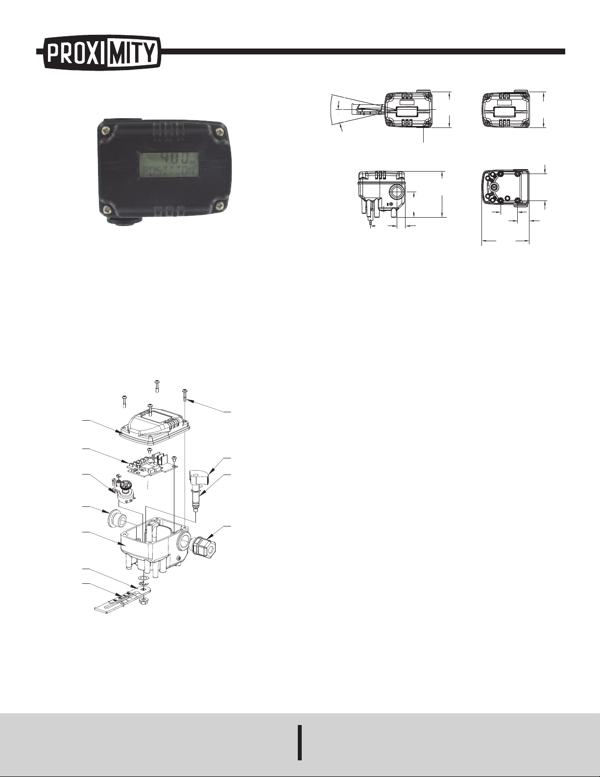
Series VPT Positioner Transmitter
20 4030
LCD
LCD
VPT-L
VPT-R
2
-29/32
[
74.00]
2-11/64
[55.00]
4
5/64
[
17.80]
2
-1/16
[
52.50]
3
-49/64
[
95.50]
3-7/8
[98.60]
1-3/8
[35.00]
6
1/64
[
24.30]
2
-11/64
[
55.00]
26° [MAX. 34°]
1
3°
2
-29/32
[
74.00]
BASE COVER
PCB BOARD
POSITION
BLIND PLUG
BASE BODY
FEEDBACK SPRING
FEEDBACK LEVER
CABLE CONNECTOR
MAIN GEAR
TRANSMETTER ASS'Y
MAIN SHAFT
C
OVER BOLT
Specifications - Installation and Operating Instructions
Bulletin V-VPT
The Series VPT Valve Position Transmitter is an ideal way to track
position of valve. With both linear and rotary motion monitoring available,
this Valve Position Transmitter can suit a wide variety of applications.
Using a resistance gear in conjunction with a potentiometer, the change
in resistance outputs a proportional current signal which is sent to the
controller. The standard LCD display allows operator to monitor the
precise position of valve.
Series VPT Parts and Assembly
Below is the assembly for the VPT-LA1 and VPT-RA1, with the only
difference being the feedback lever.
SPECIFICATIONS
Input Signal: 0 to 30°(LA1); 0 to 90°(RA1).
Output Signal: 4 to 20 mA DC.
Supply Voltage: 9 to 28 VDC.
Enclosure: Aluminum.
Electrical Connection: M20 cable gland.
Linearity: ±1% FS.
Hysteresis: ±0.2% FS.
Sensitivity: ±0.2% FS.
Enclosure Rating: IP67.
Operating Temperature: -22 to 185°F (- 30 to 85°C).
Weight: 1.3 lb (0.6 kg).
Phone: 219/879-8000 www.dwyer-inst.com
DWYER INSTRUMENTS, INC.
P.O. BOX 373 • MICHIGAN CITY, INDIANA 46360, U.S.A. Fax: 219/872-9057 e-mail: info@dwyer-inst.com
Page 2
Installation
LEVER PIN
CONNECTOR LEVER
FORK
ACTUATOR
90°
4mA
8mA
12mA
16mA
20mA
LOAD
OUTPUT
4~20mA DC
10~30V DC
NOTICE
Before installation, be sure to be aware of the following:
-Always wear safety equipment and follow safety procedures.
-As a safety precaution during installation, it is advised to shut down
valve and actuator temporarily.
-In order to prevent total shut down of system, please utilize by-pass
valve or other similar device and dissemble the valve on which the
position transmitter will be installed.
-In explosive area, please make sure no explosive gases are present at
time of installation.
Installing VPT-LA1 with Bracket
1. It is necessary to make a proper bracket to attach on the actuator
yoke. Please refer to actuator and VPT dimensions to make proper
bracket size.
The most important considerations in the design of the bracket are as
follows:
-VPT-LA1 feedback lever should be at 50% of valve stroke.
- Feedback level connection bar of actuator clamp should be connected
in the position so that the valve stroke and the numbers carved on
feedback lever are fitted. If the bracket meets the above conditions, the
VPT-LA1 can be installed very easily.
6. Insert the connection bar attached to the actuator clamp into the slot
of the VPT-LA1’s feedback lever. In order to reduce hysteresis, it should
appear as shown in step 5.
7. Check that the VPT-LA1’s feedback lever is level at 50% of valve
stroke. If not, move bracket or feedback link until it is level.
OTICE
N
nd 100%, check to see if the feedback lever is touching the lever stopper (located
a
n the backside of VPT-LA1). If touching, the VPT-LA1 should be installed further
o
away from the center of the actuator yoke.
fter installing the VPT-LA1, operate the valve stroke from 0 to
A
00% by using the air filter regulator on the actuator. At both 0
1
8. Once the VPT-RA1 is installed according to the above procedures,
tighten the bolts and nuts of the bracket and feedback lever connection
bar completely.
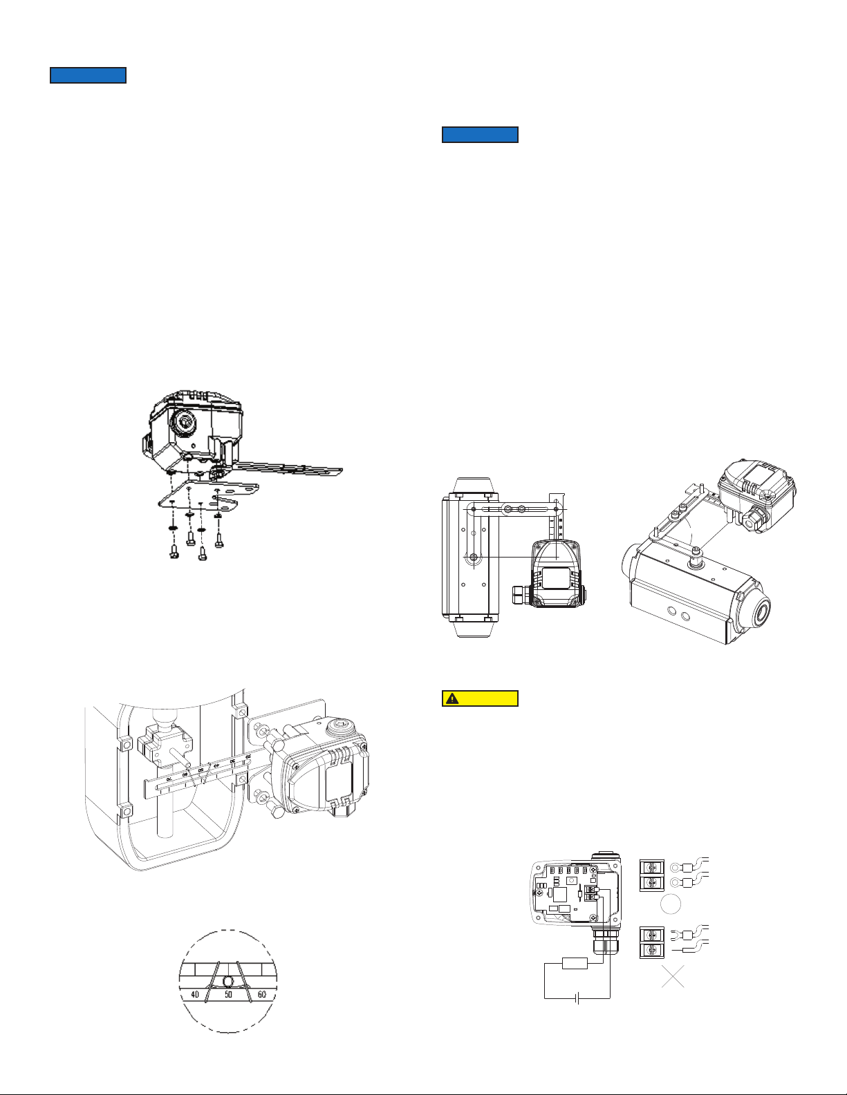
Installing VPT-RA1 with Bracket
The VPT-RA1 is designed for rotary motion valves such as Dwyer
Instruments’ ball and butterfly valves using rack and pinion, scotch yoke
or complex type actuators whose stem is rotated 90°.
1. Before installing the VPT-RA1, please set the actuator to the default
position. For single action type valves, the actuator will automatically
default itself when the air pressure shuts down. For double action type
valves, the default position must be set manually according to the
actuator’s specifications.
2. Please refer to the actuator and VPT-RA1’s dimensions in order to
make the proper bracket. See below diagram for installation with bracket.
3. After the appropriate bracket is made, install the VPT-RA1 on the
actuator and fasten all bolts and nuts completely.
2. Assemble VPT-LA1 and bracket with bolts. Use standard bolts in bolt
holes on the backside of the unit.
3. After assembling VPT-LA1 and bracket with bolts, attach it using bolt
holes of actuator yoke. Do not tighten completely. There must be some
space.
4. Connect VPT-LA1 feedback lever to the actuator clamp. The slot
length on the VPT-LA1 feedback lever is .26” (6.5 mm), so the diameter
of the connection bar should be less than .24” (6.3 mm).
5. Connect the air filter regulator with the actuator temporarily. Set the
supply pressure of the air filter so that the actuator clamp is at 50% of
valve stroke.
Power Connection
CAUTION
1. Before connecting terminal, power must be shut off.
2. Use ring type terminal against oscillation, impact, etc.
3. In order to protect Position Transmitter, the ground terminals should be
grounded.
4. Use twisted cable with conductor sectional area at least 0.0019 in²
(1.25 mm²), and suitable for 600V as on conductor table of NEC Article
310. Outer diameter of cable should be .25 to .39” (6.35 to 10 mm). Use
shielded wire against electromagnetic waves and noise.
5. Do not install the cable near equipment such as a high-capacity
transformer or motor.
Page 3

Adjustment of Potentiometer
Calibration S/W
4mA
8mA
12mA
16mA
20mA
Setting Lamp
Setting point S/W
5-POINT
2-POINT
The potentiometer is deigned to output a 12 mA signal when the
feedback lever is at 50%. In case of dislocation of the potentiometer,
please note the following before re-setting the potentiometer:
-Power must be turned off before adjusting the potentiometer.
-Be sure there is no remaining current on the PCB.
-Excessive force is unnecessary when disconnecting the potentiometer
from the PCB. Excessive force may cause damage to the transmitter.
1. Locate the potentiometer under the PCB and disconnect. Do not use
excessive force.
2. Unfasten the lock screw which locks the potentiometer gear and
remove potentiometer body from the lag-gear.
3. Fix the feedback lever at 50% and measure the resistance.
4. Rotate the pinion gear until resistance value reaches approximately
5K ohms.
5. After setting the resistance value, rotate the stopper to the normal
position and fasten the lock screw.
6. Reconnect the potentiometer to the PCB and reinstall the PCM onto
the Position Transmitter’s body.
Adjustment of Setting Points
The Series VPT Position Transmitter can be calibrated by either of the
following options.
1. 2 Point Setting: By setting the minimum and maximum points 0 and
100%, the values between the outputs are calculated and calibrated
automatically.
2. 5 Point Setting: By setting 5 points 0, 25, 50, 75, and 100%, the
outputs can be set accordingly. In general, a 5 point setting is much more
accurate.
Adjustment of Calibration
1. Input a 4 mA signal to the positioner in order to move the valve stroke
to its default position.
2. After the valve stroke reaches its default position, press the “4 mA”
button for approximately 3 to 4 seconds. The indicator light will light up,
indicating that the 4 mA position has been calibrated.
3. Please repeat the above steps for 8, 12, 16, and 20 mA settings for
the 5 point setting. For the 2 point setting, repeat the above steps only
for 20 mA.
Troubleshooting
1. VPT has no output signal
A. Check the input signal to the VPT.
B. Check power connection and polarity of terminals.
2. Input and output signals for the positioner differ greatly.
A. Check the input signal value and voltage. Insufficient voltage can
affect the input signal value.
B. Check the installation of the positioner. If the positioner is not properly
installed, reinstall properly using the positioner’s manual.
C. Reset positioner’s zero and span values. Inaccurate zero and span
settings can lower accuracy and linearity.
D. Check the installation of the VPT. If it is installed improperly, refer back
to installation section of manual.
3. Sudden change in VPT’s output signal value.
A. Make sure the VPT’s lever is placed at 50%. If not, the VPT needs to
be re-installed and adjusted to place lever at 50%.
B. Adjust the potentiometer. The potentiometer’s resistance should be at
approximately 10K ohms at the 50% point.
MAINTENANCE/REPAIR
Upon final installation of the Series VPT, no routine maintenance is
required. The Series VPT is not field serviceable and should be returned
if repair is needed. Field repair should not be attempted and may void
warranty.
WARRANTY/RETURN
Refer to “Terms and Conditions of Sales” in our catalog and on our
website. Contact customer service to receive a Return Goods
Authorization number before shipping the product back for repair. Be
sure to include a brief description of the problem plus any additional
application notes.
Page 4

©Copyright 2011 Dwyer Instruments, Inc. Printed in U.S.A. 12/11 FR# RB-443955-00
DWYER INSTRUMENTS, INC.
P.O. BOX 373 • MICHIGAN CITY, INDIANA 46360, U.S.A. Fax: 219/872-9057 e-mail: info@dwyer-inst.com
Phone: 219/879-8000 www.dwyer-inst.com
 Loading...