

Page 1
Bulletin TE-VP1
1
6-3/4
[
425.62]
4
-13/64
[
106.65]
2
[50.80]
1
-5/32
[
29.31]
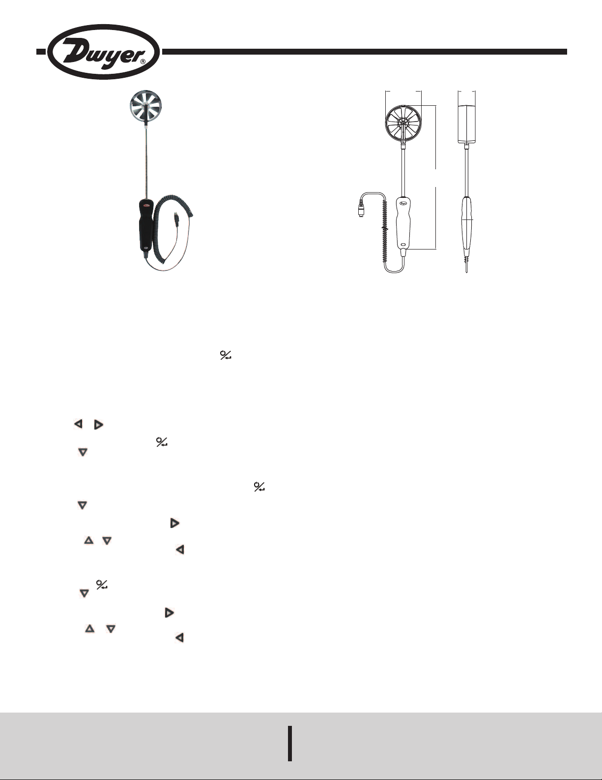
Model VP1 100 mm Vane Thermo-Anemometer Probe for UHH
Specifications - Installation and Operating Instructions
The Model VP1 100 mm Vane Thermo-Anemometer Probe measures air
velocity, air flow, humidity, and temperature when combined with the Model UHH
niversal Handheld. By having a larger diameter, the rotating vane is able to
U
easure velocities down to 50 fpm or 0.25 m/s. An arrow is molded into the vane
m
ousing to depict the flow direction.
h
PAIRING PROBES
1. Plug VP1 into UHH 6-pin probe connection on the top of the UHH.
2. Turn on Model UHH Universal Handheld by pressing the button.
SETTINGS
When using the Model VP1 Wireless 100 mm Thermo-Anemometer Probe, the
base unit can display velocity or air flow along with temperature and humidity. The
settings allow users to select velocity or air flow, engineering units, measurement
range, and which parameters to show on the display. To access the setting menus:
1. Press the or arrows to scroll through the menu headings at the top of the
display.
2. When PROBE is highlighted, hit the button to access the probe menu.
3. Press the arrow to scroll through the sub-menu headings. The currently
selected parameter will be highlighted in yellow.
Flow / Velocity Selection
1. When sub-menu TYPE (next to Anemometer) is highlighted, hit the button
to access the settings for the sub-menu.
2. Press the arrow to scroll through the parameters. The currently selected
parameter will be highlighted in yellow.
3. When DISPLAY is highlighted, press the button and velocity or vol. flow will
be highlighted.
4. Pressing the or buttons will alternate between velocity and vol. flow.
5. Once the desired selection is made, press button.
Units Selection
1. When sub-menu TYPE (next to Anemometer, Humidity or Temperature) is
highlighted, hit the button to access the settings sub-menu.
2. Press the arrow to scroll through the parameter headings. The currently
selected parameter will be highlighted in yellow.
3. When UNITS is highlighted, press the button and the current units will be
highlighted.
4. Pressing the or buttons will cycle through the available units.
5. Once the desired selection is made, press button.
SPECIFICATIONS
Service: Clean Air.
emperature Limits:
T
rocess: -4 to 140°F (-20 to 60°C);
P
mbient: 5 to 125°F (-15 to 51°C).
A
Range:
Air Velocity: 50 to 5000 fpm (0.25 to 25 m/s).
Temperature: -4 to 140°F (-20 to 60°C).
Relative Humidity: 0 to 100% RH.
Air Volume: 999,999 in selected units.
Accuracy:
Air Velocity: 0.25 to 10 m/s: ±1.5% of reading ±20 fpm (±0.1 m/s); 10 to 20
m/s: 1.5% of reading ±40 fpm (±0.2 m/s); 20 to 25 m/s: ±1.5% of reading ±60
fpm (±0.3 m/s).
Temperature: ±0.54 @ 77°F (±0.3 @ 25°C).
Relative Humidity: ±2% @ 77°F (25°C) (10 to 90% RH); ±4% (0 to 10% and
90 to 100%).
Response Time:
Air Velocity: 1 s.
Temperature: 1.5 s.
Relative Humidity: 1.5 s.
Air Volume: 1 s.
Probe Length: 8˝ (203 mm) insertion.
Vane Material: Anondized aluminum.
Handle Enclosure: Thermoplastic elastomer over polycarbonate.
Supplied With: Wrist strap.
Weight: 15.2 oz (449.52 g).
Agency Approvals: CE, RoHS.
DWYER INSTRUMENTS, INC.
Phone: 219/879-8000 www.dwyer-inst.com
P.O. BOX 373 • MICHIGAN CITY, INDIANA 46360, U.S.A. Fax: 219/872-9057 e-mail: info@dwyer-inst.com
Page 2

rea Adjustment (Only when Display is set to Volumetric Flow)
A
. When sub-menu TYPE (next to Anemometer) is highlighted, hit the button to
1
ccess the settings sub-menu.
a
2. Press the arrow to scroll through the parameter headings. The currently selected
parameter will be highlighted in yellow.
3. When AREA is highlighted, press the button to enter a new submenu that allows
election of the shape of the duct, engineering units in which the duct is measured,
s
nd the dimensions of the duct.
a
. Press the arrow to scroll through the parameter headings. The currently
4
elected parameter will be highlighted in yellow.
s
5. When the desired menu is highlighted, press the button and the current value
of the parameter will be highlighted.
6. Pressing the or buttons will cycle through the available options for each
arameter.
p
. Once the desired selection is made, press button.
7
. After all of the area parameters are made, press button.
8
Range Adjustment
1. When sub-menu TYPE (next to Anemometer) is highlighted, hit the button to
access the settings sub-menu.
. Press the arrow to scroll through the parameter headings. The currently selected
2
arameter will be highlighted in yellow.
p
. When RANGE is highlighted, press the button and the current minimum and
3
maximum of the range will be highlighted.
4. Pressing the or buttons will cycle through the available ranges.
5. Once the desired selection is made, press button.
isplay Measurements
D
OTICE
N
can be turned off.
1. When MAJOR is highlighted, press the button and the measurement type
elected will be highlighted.
s
. Pressing the or buttons will cycle through the available parameters.
2
. Once the desired selection is made, press button.
3
. In order to turn off the secondary displays, use the and to select the
4
measurement type that is not selected for the MAJOR display.
5. When the desired TYPE is highlighted, hit the button to access the settings
sub-menu.
. Press the arrow to scroll through the parameter headings. The currently selected
6
arameter will be highlighted in yellow.
p
. When VISIBLE is highlighted, press the button and either ON or OFF will be
7
ighlighted. The measurement will be displayed when set to ON and not displayed
h
when set to OFF.
8. Pressing the or buttons will alternate between ON and OFF.
9. Once the desired selection is made, press button.
AINTENANCE/REPAIR
M
pon final installation of the Model VP1, no routine maintenance is required. The
U
Model VP1 is not field serviceable and should be returned if repair is needed. Field
repair should not be attempted and may void warranty.
WARRANTY/RETURN
efer to “Terms and Conditions of Sales” in our catalog and on our website. Contact
R
ustomer service to receive a Return Goods Authorization number before shipping the
c
roduct back for repair. Be sure to include a brief description of the problem, plus any
p
additional application notes.
The measurements on the MAJOR display will always be
displayed, but the measurements on the secondary displays
©Copyright 2013 Dwyer Instruments, Inc. Printed in U.S.A. 8/13 FR# 02-444116-01 Rev. 1
DWYER INSTRUMENTS, INC.
Phone: 219/879-8000 www.dwyer-inst.com
P.O. BOX 373 • MICHIGAN CITY, INDIANA 46360, U.S.A. Fax: 219/872-9057 e-mail: info@dwyer-inst.com
 Loading...