

Page 1
Instruction Manual
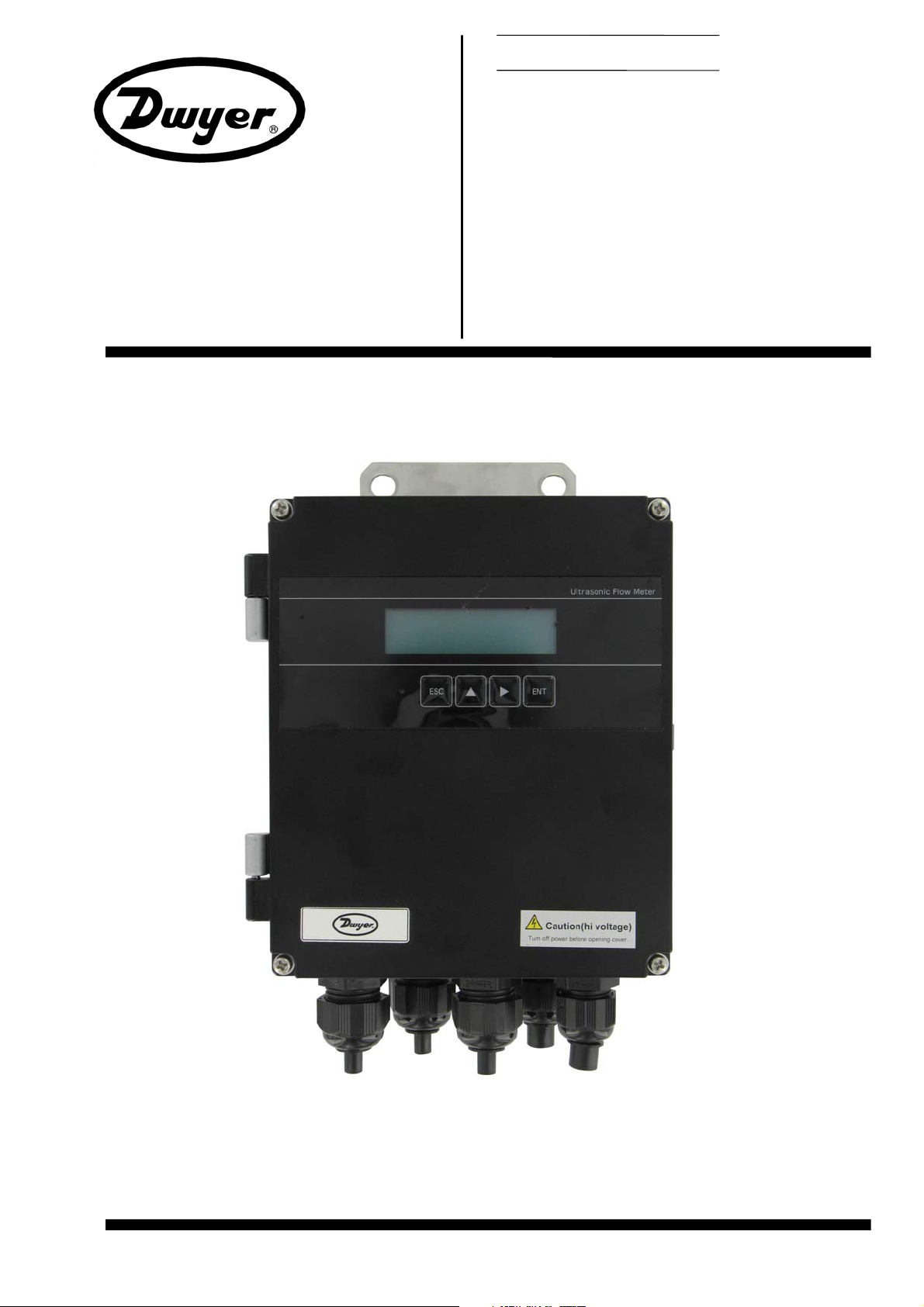
ULTRASONIC FLOWMETER
TYPE: UXF3 (Flow transmitter)
SX1, SX2 (Detectors)
Dwyer Instruments, Inc. B
ulletin F-107-UXF3
Page 2

Page 3

Bulletin F-107-UXF3
Introduction
This instruction manual concerns the installation, operation, and maintenance of the flow transmitter, detectors,
and signal cables of the ultrasonic flow meter system. This manual should be read carefully prior to installation
and operation.
zRead the manual to gain an adequate understanding of proper operation of the equipment prior to
installation and operation. Improper results or hazardous conditions may result of improper installation,
operation or maintenance.
zThe specifications of this flow meter are subject to change without prior notice for improvement of the
product.
zDo not attempt to modify the flow meter. Manufacturer shall not bear any responsibility for hazardous
conditions or improper operation as a result of unauthorized modification. If it becomes necessary to
modify the flow meter, contact the manufacturer in advance for consulation and permission.
zThis instruction manual should always be kept on hand by the party responsible for operation.
zAfter reading the manual, store it in an accessible location for reference.
zThis instruction manual should be delivered to the end user upon purchase or installation.
zIf the instruction manual has been lost, request an appropriate replacement.
Modbus is a registered trademark of Schneider Automation.
Dwyer Instruments, Inc. ©
zReproduction of this manual in whole or part is strictly prohibited
without prior written permission.
zContents of the manual are subject to change without prior notice.
Note
Issued in August, 2008
-i-
Page 4
Bulletin F-107-UXF3
SAFETY PRECAUTIONS
Before using this product, read the following safety precautions to ensure proper use.
The following items are necessary for safe operation and must be fully observed.
These safety precautions are ranked in 2 levels; "DANGER" and "CAUTION".
Warning/Symbol Meaning
Incorrect handling of the device may result in death or serious injury.
Incorrect handling may lead to a risk of physical damage or significant injury.
The items noted under " " may also result in serious equipment malfunction if not fully observed,
depending on the circumstances.
All the items must be fully observed.
Caution on mounting and piping
zThis unit is not explosion-proof. Do not use it in a place with explosive
gases. Otherwise, this may result in serious accidents such as explosion,
fire, etc.
zThe unit should be installed in a place conforming to the installation
requirements noted in this instruction manual. Otherwise, it may cause
electric shocks, fire or malfunction of the unit.
zInstall the flow meter according to the following steps to prevent it from
damage, error or malfunction.
zDuring installation, ensure the inside of the unit is free from cable chips
and other foreign objects. Otherwise, it may cause fire, failure or
malfunction.
zThe items under "Caution on Installation" noted in this manual must be
fully observed. Careless installation may result in trouble or malfunction of
the unit.
Cautions in wiring
zWhen performing wiring termination, observe appropriate instructions to
prevent ingress by moisture, dew condensation or water leaks, follow
“Section 3.4 – Flow transmitter wiring” described in this manual.
zBefore performing the wiring work, be sure to turn OFF the main power.
Otherwise, electric shock may result.
zDo not perform wiring work outdoors in inclement weather to prevent
insulation deterioration and dew condensation. Otherwise, malfunction or
accelelerated deterioration may result.
zBe sure to connect a power source of correct rating. Use of improper
power sources out of rating may cause fire.
zThe unit must be grounded as specified. Otherwise, it may result in electric
shocks, malfunction, etc.
zThe signal cable and analog output signal cable should be wired as far
away as possible from high-voltage lines to prevent entry of noise signals
as it will result in malfunction of the unit.
zTo prevent malfunction of the unit, the analog output signal cable and the
power supply cable may require separate conduits.
-ii-
Page 5

Bulletin F-107-UXF3
Caution on maintenance and inspection
zThe unit should be inspected every day to ensure proper operation.
zWhen measuring the insulation resistance between the power/output
terminal and the case, follow “Section 6.2.3 – How to measure insulation
resistance” described in this manual.
zIf the fuse is blown, detect and eliminate the root cause, and then replace
the fuse with a spare. If there are no spares, replace the fuse with the
appropriate part specified in this manual. Use of a fuse other than
specified or its short-circuit may cause an electric shock or fire. The fuse
should be replaced according to “Section 6.3 – How to replace the fuse”
described in this manual.
-iii-
Page 6
Bulletin F-107-UXF3
CAUTION ON INSTALLATION LOCATION
(1) A location that provides enough space for periodic inspection and wiring work.
(2) A location not exposed to direct sunlight nor inclement weather.
(3) A location free from excessive vibration, dust, dirt and moisture.
(4) A location not subjected to radiated heat from a heating furnace, etc.
(5) A location not subjected to corrosive atmosphere.
(6) A location not to be submerged.
(7) A location remote from electrical devices (motor, transformer, etc.) which generate
electromagnetic induction noise, electrostatic noise, etc.
(8) A location not subjected to excessive fluid pulsation such as pump discharge side.
(9) A location that provides enough place for the length of the straight pipe.
(10) A location where ambient temperature and humidity are -20 to +50°C and 95% RH or less for
flow transmitter, -20 to +60°C and 100% RH or less for detector.
-iv-
Page 7

Contents
Bulletin F-107-UXF3
Introduction ··········································································i
SAFETY PRECAUTIONS··················································· ii
CAUTION ON INSTALLATION LOCATION ·······················iv
1. PRODUCT OUTLINE······················································1
1.1. Checking delivered items ·········································1
1.2. NAME AND FUNCTION OF EACH PART················2
1.2.1. Flow transmitter : UXF3 ·····································2
1.2.2. Reserved ··························································4
1.2.3. Reserved ···························································4
1.2.4. Small/middle size detector (SX1)·······················4
1.2.5. Large size detector (SX1) ··································5
1.2.6. Small diameter/High temperature detector
(SX2) ·························································6
2. INSTALLATION AND BEFORE START OF
OPERATION OF THE FLOW TRANSMITTER ············7
2.1. Outline of installation procedure·······························7
3. INSTALLATION·······························································8
3.1. Installation location of flow transmitter······················8
3.2. Installation location of detector·································9
3.2.1. Length of straight pipe ·····································10
3.2.2. Mounting position·············································11
3.3. Installation of flow transmitter·································12
3.3.1. Wall mounting (Flow transmitter : UXF3 ··········12
3.3.2. 2B pipe stand mounting (Flow transmitter :
UXF3 ·······················································12
3.3.3. Reserved ·························································13
3.3.4. Reserved ·························································13
3.4. Flow transmitter wiring ···········································14
3.4.1. Cautions in wiring ············································14
3.4.2. Applicable wires ···············································14
3.4.3. Treatment of wiring port ···································14
3.4.4. Wiring to each terminal ····································15
3.4.4.1. Flow transmitter : UXF3·····························15
3.4.4.2. Reserved···················································16
4. Parameter ·····································································17
4.1. Description of display/setting unit···························17
4.1.1. Flow transmitter : UXF3 display/setting unit·····17
4.1.2. Reserved ························································17
4.1.3. Description of display/setting unit ····················18
4.2. Composition of key operation·································19
4.3. Parameter initial value list ······································24
4.4. Parameter protection··············································26
4.4.1. Parameter protection ON/OFF·························26
4.5. Display language····················································27
4.5.1. How to select the language······························27
4.6. Checking and Setting of Piping
Specifications/Detector ····································28
4.6.1. Checking piping parameter······························28
4.6.2. Piping parameter setting method·····················29
4.7. Zero Adjustment·····················································32
4.8. Setting of unit ·························································33
4.8.1. How to set the unit system·······························33
4.8.2. How to set the flow rate unit ····························34
4.8.3. How to set the total unit ···································35
4.9. Output Setting ························································36
4.9.1. Setting of flow rate range·································36
4.9.1.1. Setting of flow rate range (single range) ···36
4.9.1.2. Setting of analog output at error
(Burnout)············································37
4.9.1.3. Output limit················································38
4.9.2. Setting the total················································39
4.9.2.1. Setting the total pulse (pulse value,
pulse width)········································39
4.9.2.2. Setting the preset value ····························41
4.9.2.3. TOTAL mode ·············································42
4.9.2.4. Determining how to dispose of total at
error (BURNOUT) ······························43
4.9.3. Setting the DO output ······································44
4.9.3.1. How to validate the total pulse output ·······44
4.9.4. Setting the LCD indication ·······························46
4.9.5. Setting the damping·········································47
4.9.6. Setting the low flow rate cutting ·······················48
4.10. Application operation of parameter·······················49
4.10.1. Setting automatic 2 ranges ····························49
4.10.2. Setting the Bi-directional range······················51
4.10.3. Setting the Bi-directional auto 2 range···········52
4.10.4. Rate limit························································55
4.10.5. Setting the DO output ····································57
4.10.5.1. How to validate outputting the FULL
SCALE 2············································57
4.10.5.2. How to validate the alarm output·············58
4.10.5.3. Setting the flow switch·····························59
4.10.5.4. How to validate the total switch ···············61
4.10.5.5. How to validate the range over output
and pulse range over output ··············62
4.10.5.6. How to validate the output at the minus
direction action···································63
4.10.6. Setting the DI input ········································64
4.10.6.1. Invalidating the DI input···························64
4.10.6.2. How to validate the total preset with the
external contact. ································65
4.10.6.3. How to validate the zero adjustment
with the external contact. ···················66
4.10.7. How to compensate the measurement
value························································67
4.10.8. Setting of the operation mode························68
4.11. MAINTENANCE MODE········································69
4.11.1. How to calibrate the analog output·················69
4.11.2. How to set the constant current output···········70
4.11.3. How to check the action of total pulses··········71
4.11.4. How to check the status output ······················72
4.11.5. How to check the DI input ······························73
4.11.6. How to validate the test mode (simulated
flow rate output)·······································74
4.11.7. How to validate a serial transmission (RS-
485) ·························································76
-v-
Page 8

Bulletin F-107-UXF3
4.11.8. How to set the ID No. ···································· 78
4.11.9. How to confirm the software version ············· 78
4.11.10. Initializing setting parameters ······················ 79
4.11.11. How to set the detailed setting····················· 80
5. Mounting of detector ···················································· 82
5.1. Detector mounting procedure ································ 82
5.1.1. Mounting of detector ······································· 83
5.1.2. Image figure of mounting dimension ··············· 83
5.2. Selection of mounting position······························· 84
5.3. Selection of mounting method ······························· 85
5.4. Processing of mounting surface ···························· 86
5.5. How to determine the mounting position ··············· 87
5.6. Selection of acoustic couplant ······························· 88
5.7. Cable end treatment ·············································· 89
5.7.1. Cable end treatment for SX2··························· 89
5.7.2. Cable end treatment for SX1··························· 89
5.8. Reserved for Future Use ······································· 90
5.8.1. Reserved························································· 90
5.8.2. Reserved························································· 90
5.9. Mounting small-diameter and medium size
sensor (SX1) ··················································· 91
5.9.1. Connection of sensor cable····························· 91
5.9.2. Assembly procedure of the sensor ·················· 93
5.9.3. Mounting method on the pipe·························· 94
5.9.3.1. In case of V method·································· 94
5.9.3.2. In case of Z method·································· 96
5.10. Mounting large size detector (SX1) ····················· 97
5.10.1. Connection of sensor cable··························· 97
5.10.2. Mounting method on the pipe························ 98
5.11. Mounting small diameter detector (SX2)·············· 99
5.12. Mounting high temperature detector (SX2)········ 100
5.12.1. Mounting of detector (in case of V method) 100
5.12.2. Mounting of detector (in case of Z method)· 101
6.6.1.1. Checking the LCD/LED ···························111
6.6.1.2. Checking the LED lit in red······················112
6.6.1.3. Checking the RAS information ················113
6.6.2. Displaying the data in maintenance mode ·····114
6.6.3. Keying is abnormal ········································115
6.6.4. Error in measured value·································116
6.6.5. Error in analog output ····································118
6.6.6. Checking received waveforms ·······················119
6.6.6.1. How to connect the oscilloscope ·············119
6.6.6.2. Checking sending/receiving···················· 120
6.6.7. Remedying a hardware fault ····················· 122
7. Appendix ···································································· 123
7.1. How to make gauge paper ·································· 123
7.2. Piping data ·························································· 124
6. CHECK AND MAINTENANCE ··································· 102
6.1. Daily Check ························································· 102
6.2. Periodic Inspection ·············································· 102
6.2.1. Checking zero point ······································ 102
6.2.2. Reapplying grease ········································ 102
6.2.3. How to measure the insulation resistance····· 103
6.2.3.1. Flow transmitter : UXF3·························· 103
6.2.3.2. Reserved ················································ 104
6.3. How to replace the fuse······································· 105
6.3.1. Flow transmitter : UXF3 ································ 105
6.3.2. Reserved······················································· 106
6.4. How to replace the relay······································ 107
6.4.1. Flow transmitter : UXF3 ································ 107
6.4.2. Reserved······················································· 108
6.5. How to replace the LCD ······································ 109
6.5.1. Flow transmitter : UXF3 ································ 109
6.5.2. Reserved························································110
6.6. ERROR AND REMEDY········································110
6.6.1. Display error···················································111
-vi-
Page 9
1. PRODUCT OUTLINE
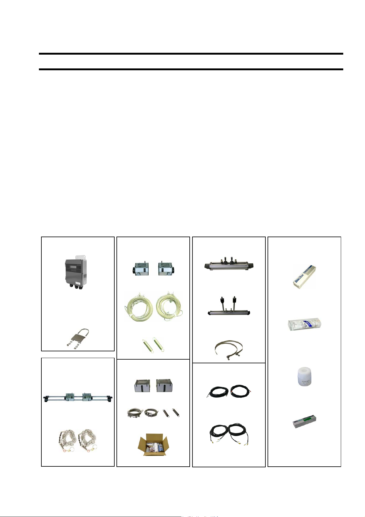
1.1. Checking delivered items
Flow transmitter (UXF3)
Flow transmitter main unit ········································· 1 set
Waterproof gland (Built into the main unit) ················ 1 set
Wall mount frame (Built into the main unit)················ 1 set
Panel mounting bracket (option)
(U bolt, support fixture, butterfly nut 2 pieces,
spring washer 2 pieces, plain washer 2 pieces) ········ 1 set
Detector (SX1-A)
Small size detector···················································· 1 set
Chain × 2··································································· 1 set
Silicone rubber, optional silicone-free grease or
silicone grease ······················································ 1 piece
Detector (SX1-B)
Middle size detector × 2 ············································ 1 set
Wire rope × 2 ···························································· 1 set
Mounting spring × 2··················································· 1 set
Silicone rubber, optional silicone-free grease or
silicone grease ······················································ 1 piece
Detector (SX1-C)
Large size detector × 2·············································· 1 set
Wire rope × 2 ···························································· 1 set
Mounting spring × 2··················································· 1 set
Detector mounting set ···············································1 set
Bulletin F-107-UXF3
Detector (SX2-A)
Small diameter detector ············································ 1 set
Stainless steel belt ···················································· 1 set
Silicone rubber, optional silicone-free grease or
silicone grease ·······················································1 piece
Detector (SX2-B)
High temperature detector ········································ 1 set
Stainless steel belt ···················································· 1 set
Silicone grease (for high temperature detector) ·····1 piece
Signal cable (for SX1) (length specified) × 2 ················ 1 set
Signal cable (for SX2) (length specified) × 2 ················ 1 set
CD-ROM (Instruction manual and loader software)···1 piece
Not included
Power cable
Output signal cable
RS-485 communication cable
Flow transmitter (UXF3)
(IP66)
Pipe mounting bracket
(option)
Detector (SX1-A)
Small size detector
Chain
Detector (SX1-B)
Middle size detector
Wire rope
Mounting spring
Detector (SX1-C)
Large size detector
Wire rope & springs
Detector mounting set
Detector (SX2-A/B)
Small diameter detector
High temperature detector
Stainless steel belt
Signal cable (for SX1)
Signal cable (for SX2)
Acoustic coupler
Silicone rubber
Silicone-free grease
Silicone grease for high
temperature
Silicone grease
-1-
Page 10
Bulletin F-107-UXF3
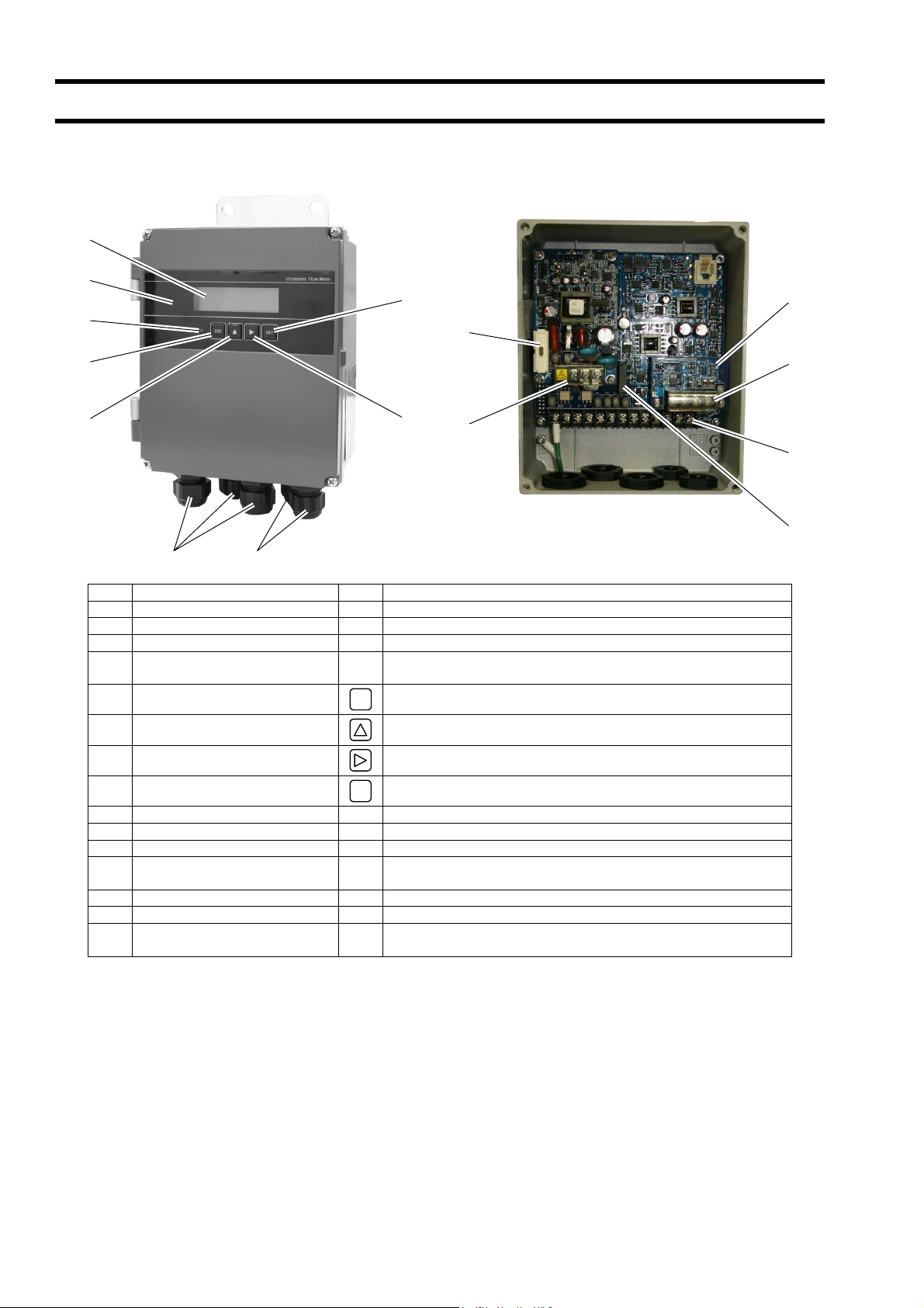
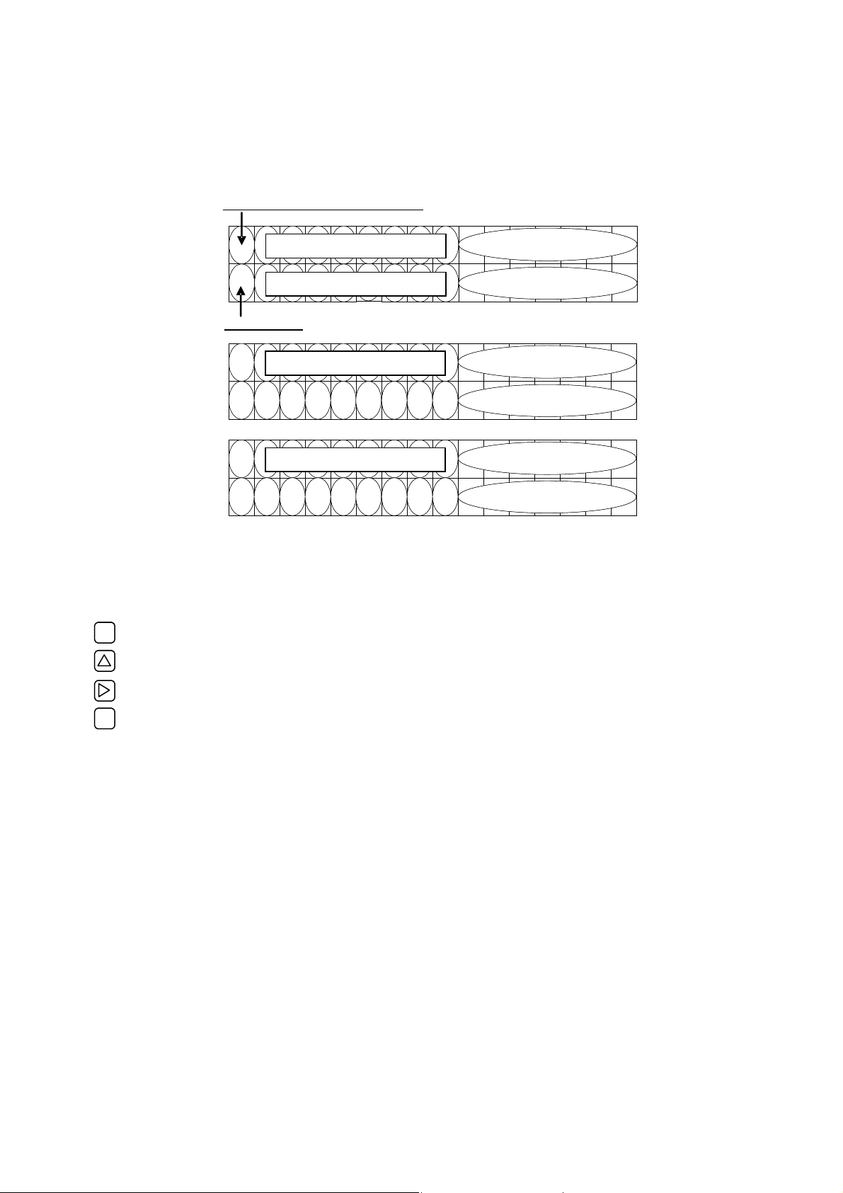
1.2. NAME AND FUNCTION OF EACH PART
1.2.1. Flow transmitter : UXF3
(9)
(3)
(4)
(8)
(15)
(13)
(5)
(6)
(1) (2)
No. Name Key Description
(1) Wiring connection port, large Wiring connection port for power cable and output cable.
(2) Wiring connection port, small Wiring connection port for signal cable only.
(3) Indication and setting unit Indicates and sets the flow rate, etc.
Received wave diagnostic
(4)
indication (LED)
(5) Escape key
(6) UP key Selects items, numeric values and symbols.
(7) Shift key Moves the cursor and selects decimal place.
(8) Entry key
(9) LCD display Indicates the flow rate or setting.
(10) Power terminal Connects the power cable.
(11) Input/output terminal Connects signal cable, analog output or DO output cable.
(12) Communication board terminal
(13) Fuse holder Fuse holder
(14) Relay Relay contact for DO3 output
(15) Communication board
ESC
ENT
(7)
(10)
Indicates whether received wave is normal (green) or abnormal
(red).
Returns to the next-higher menu level or cancels the set status.
Enters a selection or registers a setting.
Connects communication cable.
(A communication board is optional)
Mounted if communication synchronization is optionally
designated.
(12)
(11)
(14)
-2-
Page 11

Bulletin F-107-UXF3
(Page intentionally blank)
- 3 -
Page 12
Bulletin F-107-UXF3
1.2.2. Reserved
1.2.3. Reserved
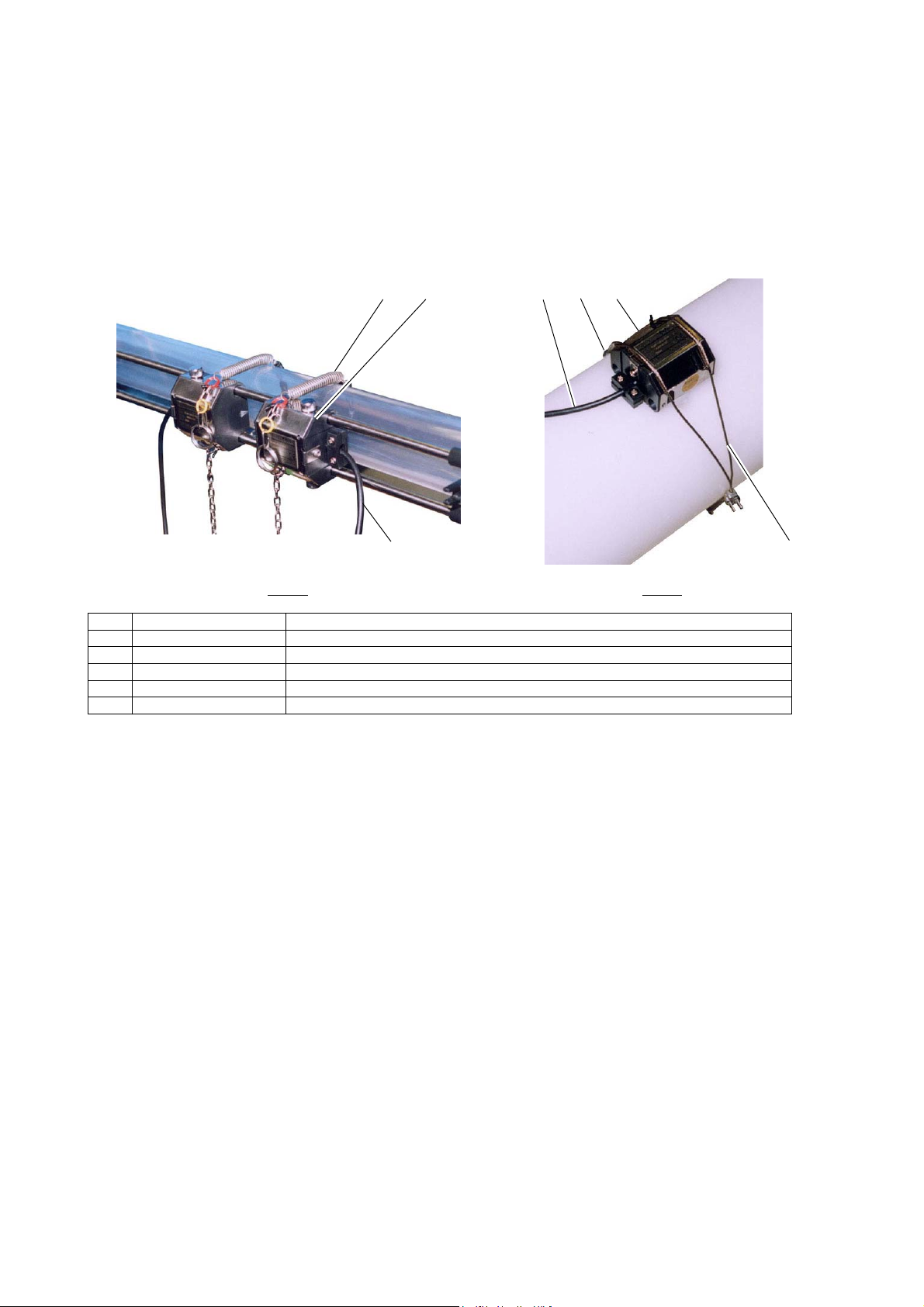
1.2.4. Small/middle size detector (SX1-A, SX1-B)
(3) (2)
(1)
SX1-A
No. Name Description
(1) Signal cable Transmits send/receive signals.
(2) Detector Sends and receives an ultrasonic wave.
(3) Chain Fastens the detector on pipe.
(4) Wire rope Fastens the detector on pipe.
(5) Mounting spring Removes the play of wire rope.
SX1-B
(5)(1)
(2)
(4)
- 4 -
Page 13
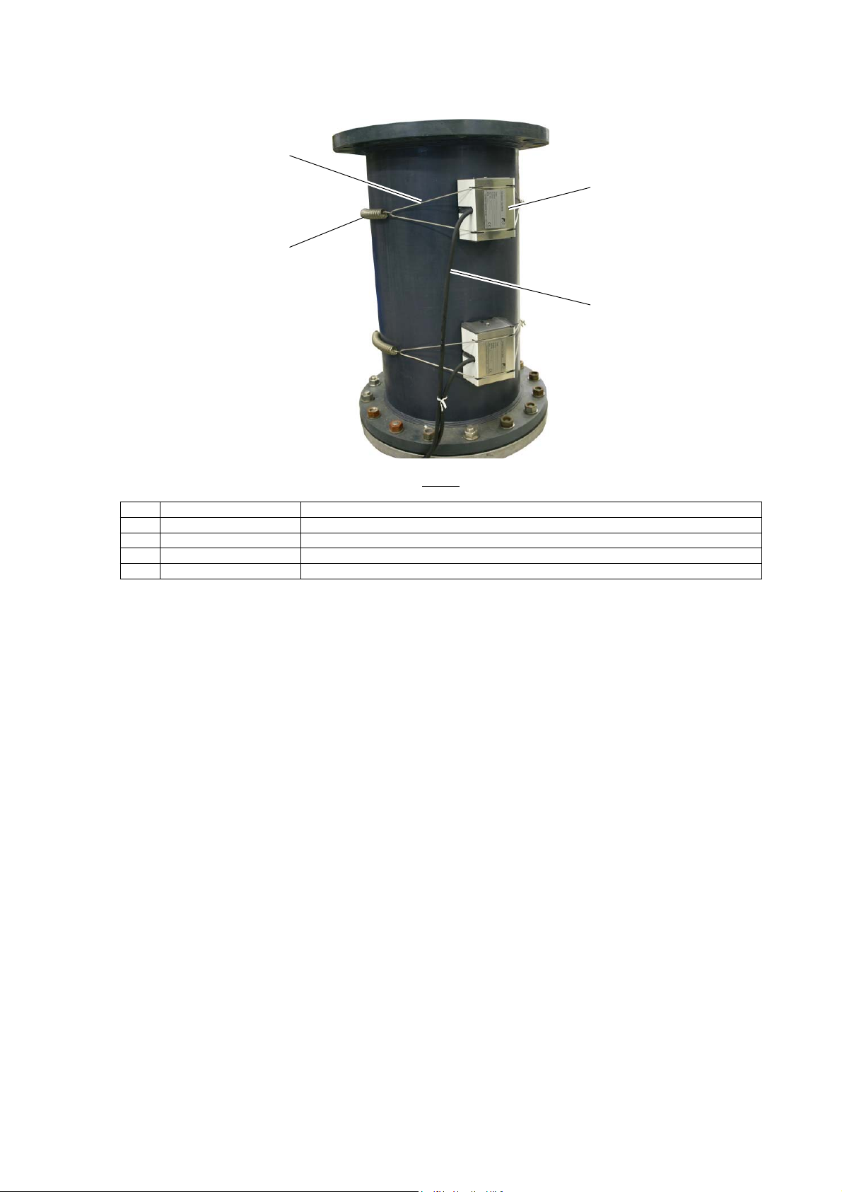
1.2.3. Large size detector (SX1-C)
(3)
(4)
Bulletin F-107-UXF3
(2)
(1)
SX1-C
No. Name Description
(1) Signal cable Transmits send/receive signals.
(2) Detector Sends and receives an ultrasonic wave.
(3) Wire rope Fastens the detector on pipe.
(4) Mounting spring Removes the play of wire rope.
- 5 -
Page 14
Bulletin F-107-UXF3
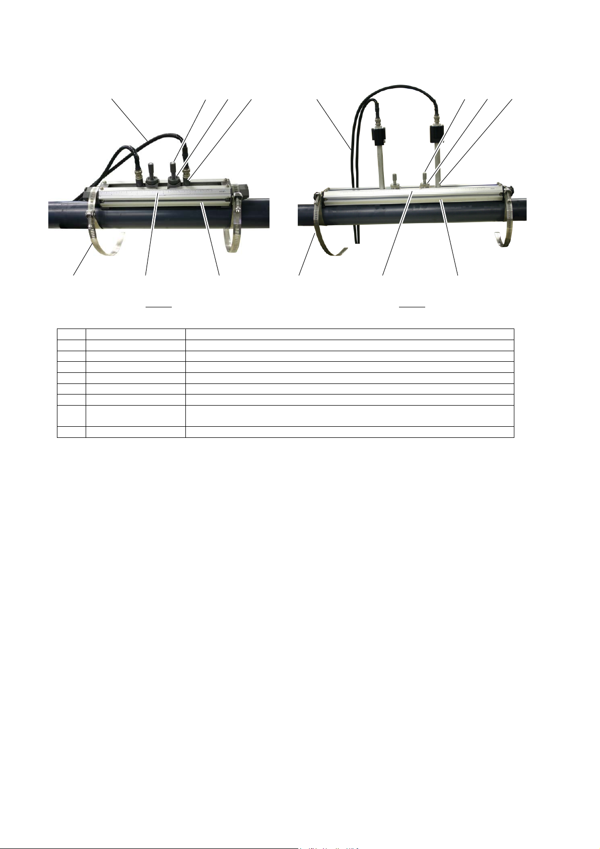
1.2.4. Small diameter/High temperature detector (SX2-A, SX2-B)
(1) (1)(4)(3) (3)(2) (4)
(5)(8) (6)
SX2-B
SX2-A
No. Name Description
(1) Signal cable Transmits the send/receive signals.
(2) Sensor unit Sends and receives an ultrasonic wave.
(3) Element holder Attaches the sensor unit firmly to the pipe.
(4) Lock nut Fixes the sensor unit mounting position.
(5) Scale Reads the spacing between the sensor units.
(6) Frame Fastens the sensor unit on pipe.
(7) High temperature
detector
(8) Stainless steel belt Fastens the sensor frame on pipe.
Sends and receives an ultrasonic wave.
(5)(8) (6)
(7)
- 6 -
Page 15
Bulletin F-107-UXF3
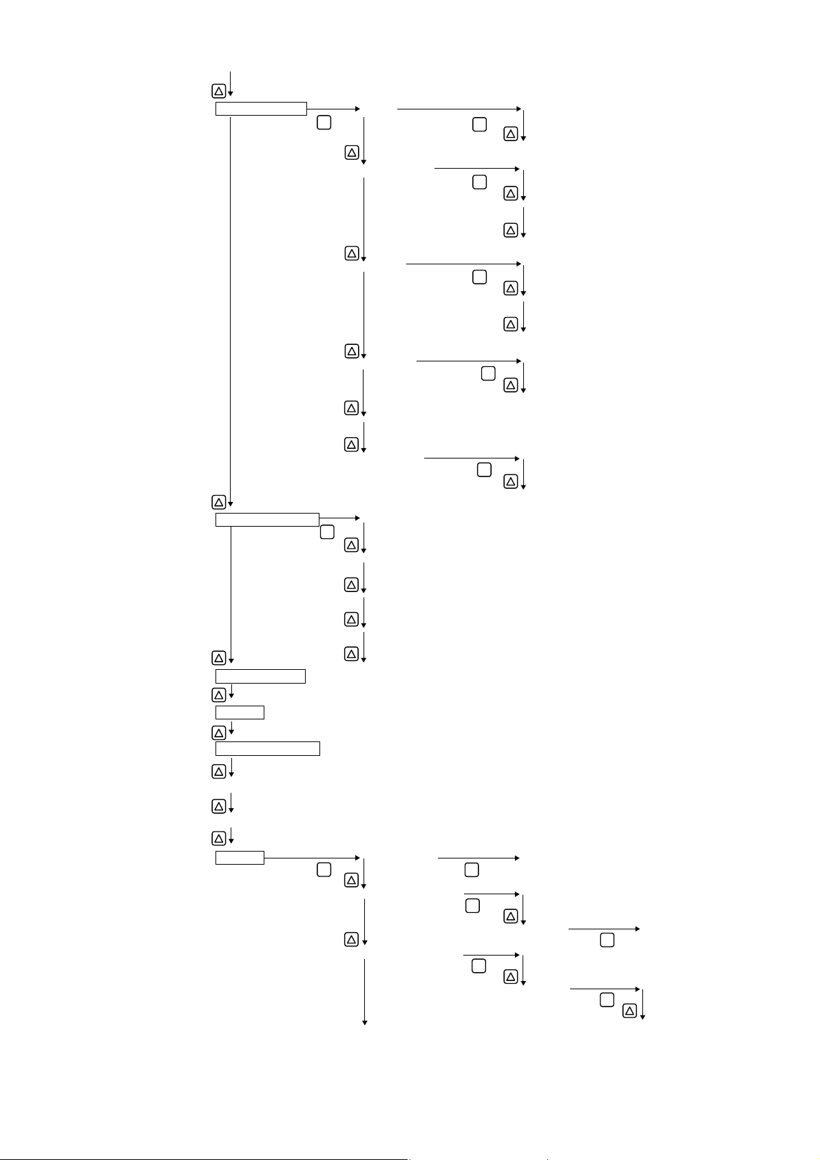
2. INSTALLATION AND BEFORE START OF
OPERATION OF THE FLOW TRANSMITTER
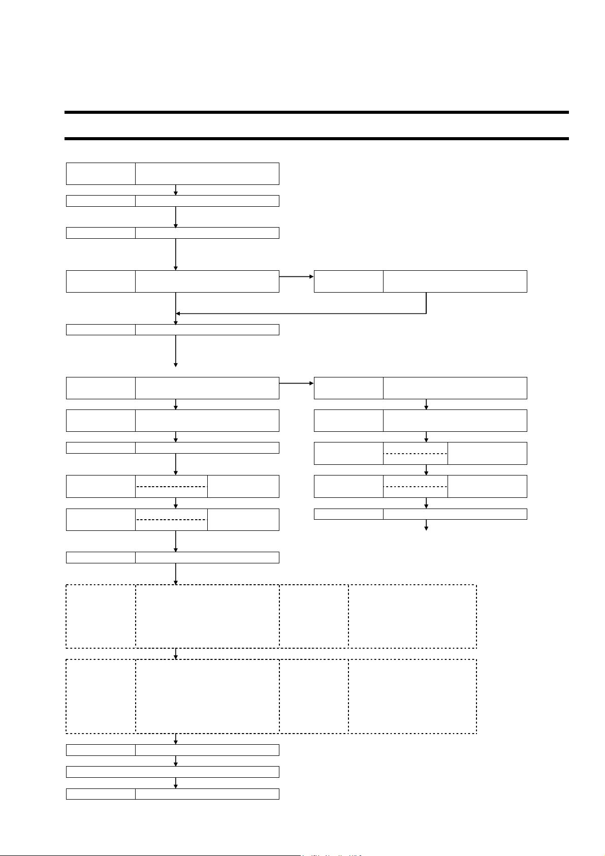
2.1. Outline of installation procedure
Section 3.3
Section 3.4
Power ON *
Section 4.4 Parameter protection * Metric system is selected for unit.
*
NG
Section 4.6
OK
Section 5 Mounting of detector *
NG (LED display is red)
Section 6.6.1.3 Checking the RAS information Section 6.6.2
OK (LED display is green)
Section 6.6.2
Check the data display AGC U
AGC D
AGC U P/H U
AGC D
P/H U Section 6.6.6 Checking received waveforms
P/H D
Contact manufacturer's service representative.
Section 4.7 Zero Adjustment *
Basic operation Section 4.9.1.3 Output limit
Section 4.8.1 How to set the unit system Section 4.9.2 Setting the total
Section 4.9.1.2 Setting of analog output at error
Application operation
Section 4.9.1 Setting of flow rate range
Section 4.10.1 Setting automatic 2 ranges
Section 4.10.2 Setting the Bi-directional range Section 4.10.5.3 Setting the flow switch
Section 4.10.3 Setting the Bi-directional auto 2
Section 4.10.6 Setting the DI input
Section 7.3 ORDERING INFORMATION
Section 6 CHECK AND MAINTENANCE
Installation of flow transmitter
Flow transmitter wiring
Checking and Setting of Piping
Specifications/Detector
Displaying the data in
maintenance mode
35% or more
5528 to 6758
range)
(Burnout) Section 4.9.4 Setting the LCD indication
range
Run (Measurement)
Check the power supply specifications and wiring before
turning on the power. (Refer to “1.2.Check on type and
specifications”.)
The initial display language is English. Switch the languages
as required.
Section 4.6.2 Piping parameter setting method
Be careful not to mount the sensor units with wrong mounting
dimension. Mount it with the dimension displayed at the
process setting of the piping parameter. (Refer to “5.
Mounting of detector”.)
Displaying the data in
maintenance mode
Check the data display
35% or more
Outside the range
P/H D
Before performing zero point adjustment, check that the pipe
is filled with fluid, the fluid is in still state, and that the
measurement status is normal.
Section 4.9.3 Setting the DO output Section 4.9.1.1 Setting of flow rate range (single
Section 4.9.3.1 How to validate the total pulse
output
Section 4.10.5.2 How to validate the alarm
output
Section 4.10.5.4 How to validate the total
switch
of 5528 to 6758
-7-
Page 16
Bulletin F-107-UXF3
3. INSTALLATION
Select an installation location that satisfies the following conditions for ease of maintenance and inspection, service life of
the instrument, and assurance of reliability all considered.
CAUTION
(1) A location where ambient temperature and humidity are -20 to +55°C and 90% RH or less for transmitter
(UXF3), -20 to +80°C and 90% RH or less for detector (SX1) and -20 to +60°C and 90% RH or less for
detector (SX2).
(2) A location not exposed to direct sunlight nor inclement weather.
(3) Space for periodic inspection and wiring work is available.
(4) A location not subjected to radiated heat from a heating furnace, etc.
(5) A location not subjected to corrosive atmosphere.
(6) A location not to be submerged.
(7) A location free from excessive vibration, dust, dirt and moisture.
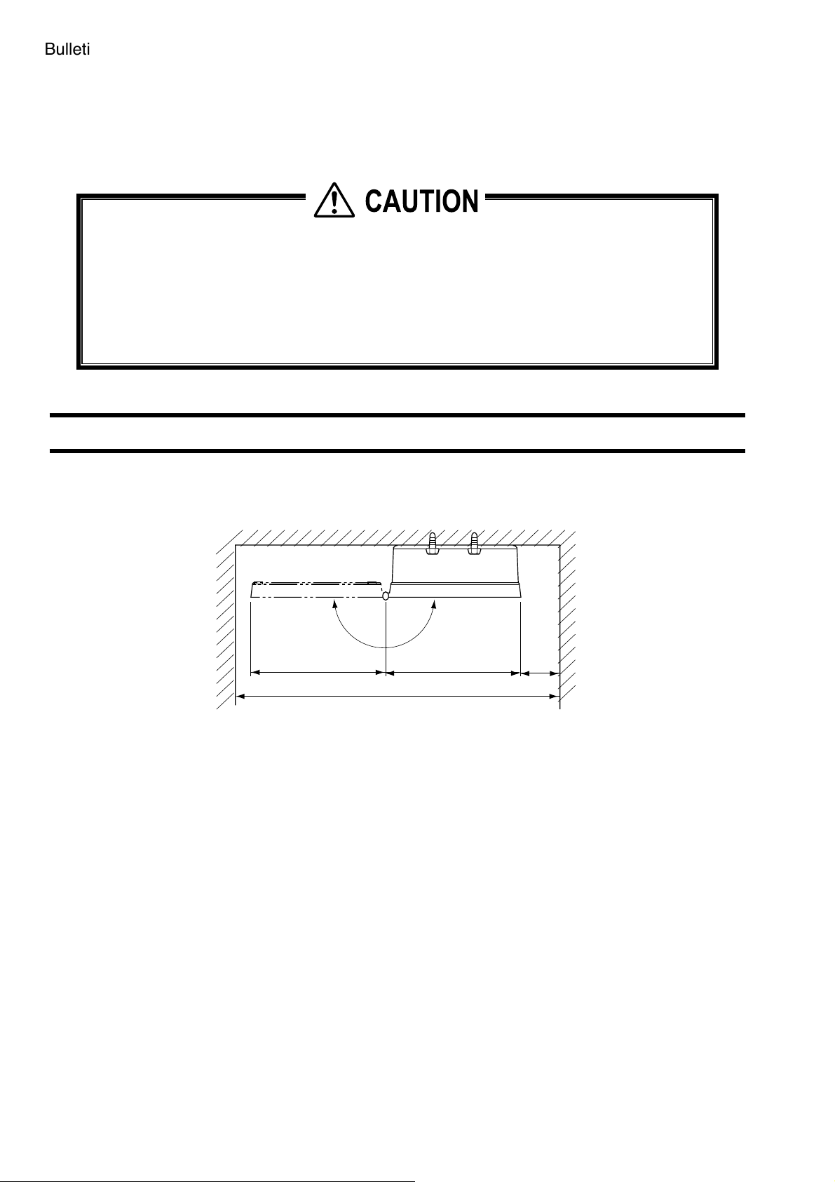
3.1. Installation location of flow transmitter
Secure at least 100 mm (3.94 in.) of space between the flow transmitter and nearby wall. Also secure a space of opening the front
cover in case of maintenance.
Allow space for cable wiring under the case.
N
E
P
O
147(5.79)
400(15.75) or more
Fig. 3.1 Top view of mounting (Flow transmitter : UXF3) [unit: mm(inch)]
147(5.79)
>100
(3.94)
-8-
Page 17
Bulletin F-107-UXF3
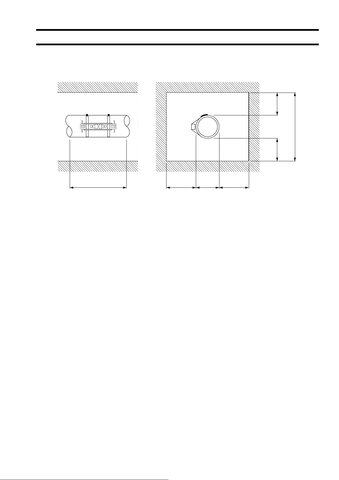
3.2. Installation location of detector
The measuring accuracy is considerably affected by the detector mounting place, including physical setup of pipe to
measuring a flow rate. Select a location which meets the condition in section 3.2.1. (Length of straight pipe). Also, reserve
enough space for installation and maintenance referring to the following diagram.
>200
(7.87)
>2000
(78.74)
>200
(7.87)
D+1200(47.24) or more >600(23.62) D >600(23.62)
Adequate space for the installation location of detector
D : Pipe diameter
Unit : mm(inch)
-9-
Page 18
Bulletin F-107-UXF3
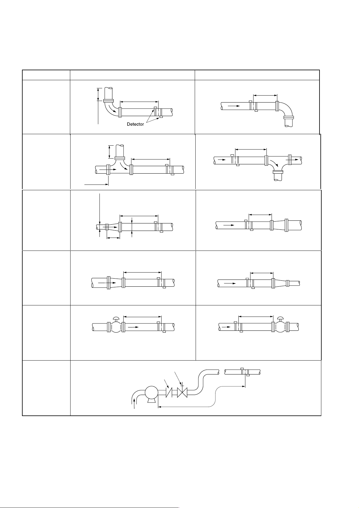
3.2.1. Length of straight pipe
The length of upstream and downstream straight pipe of the ultrasonic detector should be long enough to ensure accurate
measurements.
(D is nominal diameter for a pipe)
Type Length of upstream straight pipe Length of downstream straight pipe
L≥5D
L≥10D
90° vending
10D or more
L≥10D
L≥50D
Tee
10D or more
10D or more
Extension pipe
Contraction pipe
Individual valves
Pump
L≥30D
0.5D or more
D
1.5D or more
L≥10D
L≥30D
When adjusting flow rate by the valve on the
upstream side
Isolation valve
Check valve
P
L≥5D
L≥5D
L≥10D
When adjusting flow rate by the valve on the
downstream side
L≥50D
Note) Source: Japan Electric Measuring Instruments Manufacturers' Association (JEMIS-032)
-10-
Page 19
Bulletin F-107-UXF3
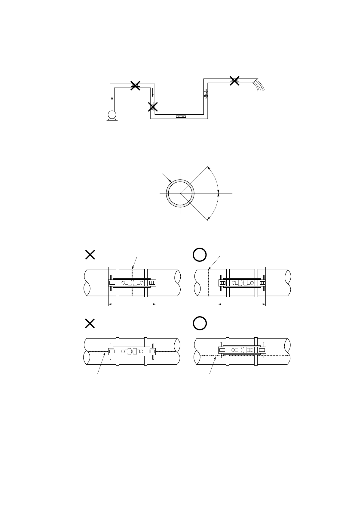
3.2.2. Mounting position
The detector can be installed vertical, horizontal or at any position provided that attention is paid to the following things.
(1) The piping must completely be filled with fluid when it flows.
Air-collecting
Pipe may
not be filled
with liquid.
Pump
Pipe may not be filled with liquid.
Good
Good
(2) Where a horizontal pipe is used, install the sensor within ±45° from the horizontal plane. Otherwise, the measurement
could be impossible if bubbles stay in the upper part of piping or if deposits are accumulated in the lower part of piping.
In case of vertical piping, the detector may be mounted at any position on its periphery provided that the flow is upward.
Pipe
45
Horizontal
45
(3) Avoid installing the sensor on a deformed portion of pipe or welded portion of pipe, or on flange.
Welded part
Welded part is provided.
Welded part is straddled.
Welded part
Welded part is not provided.
Remove the welded part.
-11-
Page 20
Bulletin F-107-UXF3
3.3. Installation of flow transmitter
The flow transmitter may be mounted on a wall or 2B pipe stand (option).
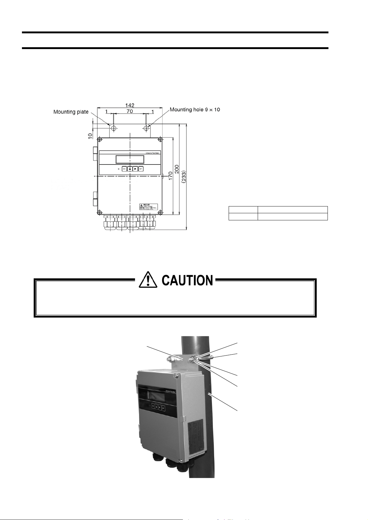
3.3.1. Wall mounting (Flow transmitter : UXF3)
For wall mounting, use two M8 bolts.
Drill holes according to the mounting hole dimensions shown below, and fasten the flow transmitter using the M8 bolts.
[unit: mm]
Nominal Standard tightening torque
M8
3.3.2. 2B pipe stand mounting (Flow transmitter : UXF3)
When mounting on 2B pipe, be sure to use a complete set of fixtures (U bolt, support fixture, plain washer,
spring washer, nut) furnished if optionally designated. Tighten the nut by hand. If any support fixture is not used
or if the assembly is excessively tightened by tool, the wall mounting fixture may be damaged.
Mount the instrument on 2B pipe stand as illustrated below.
Support fixture
Plain washer
U bolt (M8)
Spring washe
Nut
r
12.5 [Nm]
- 12-
2B pipe stand
Page 21

Bulletin F-107-UXF3
(Page intentionally blank)
Page 22
Bulletin F-107-UXF3
3.4. Flow transmitter wiring
3.4.1. Cautions in wiring
(1) Use a special coaxial cable as a signal cable between the detector and flow transmitter. Do not provide a
junction or splice of the signal cable midway.
(2) The signal cable between the detector or flow transmitter should be run in metallic conduits. Upstream and
downstream signal cables may be put in the same conduit but, to avoid interference, do not put the power
cable together with the signal cables.
(3) For output signal, use a shielded cable, where possible.
(4) To avoid noise interference, do not put the cables together with heavy duty line or the like into the same
duct.
(5) If a ground wire is included in the power cable, connect it to ground properly.
(6) A power switch is not provided on the instrument and must be mounted separately if desired.
(7) Seal unused wiring ports with available caps.
3.4.2. Applicable wires
Use the following cables.
z Power cable : 3-wire or 2-wire cabtyre cable
Nominal sectional area 0.75mm
Outside diameter Ɏ11mm (0.433 in)
z Output signal cable : 2-wire or multi-wire cabtyre cable as required
Outside diameter Ɏ11mm (0.433 in)
z Detector-flow transmitter cable : Signal cable by type designation
2
(0.00117 in2) or more
In case of SX1 : High-frequency coaxial double shield cable with characteristic
impedance of 50ȍ
Outside diameter Ɏ7.3mm (0.288 in)
In case of SX2 : High-frequency coaxial double shield cable with characteristic
impedance of 50ȍ
With one-side waterproof BNC connector
Outside diameter Ɏ7.3mm (0.288 in.)
3.4.3. Treatment of wiring port
The casing of the flow transmitter is IP66. However, if installed in a humid place, the wiring ports must be made airtight to
avoid ingress of moisture, condensation, etc. Be sure to use the waterproof glands furnished with the instrument in order to
ensure the waterproof capability. A gland, which is not ready to be used, should be sealed with the supplied cover.
Do not install the instrument where there is a risk of flooding.
- 14 -
Page 23
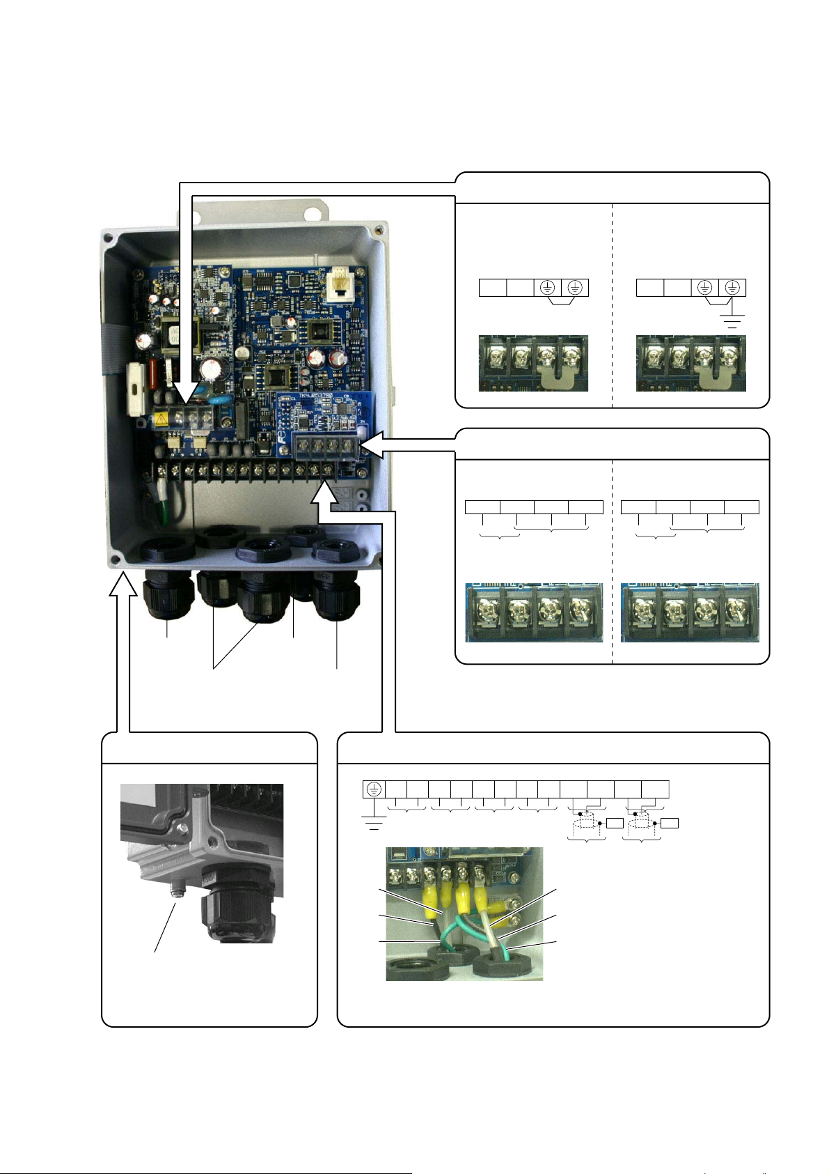
3.4.4. Wiring to each terminal
3.4.4.1. Flow transmitter :
Carry out wiring to each terminal according to the following figure.
Bulletin F-107-UXF3
Power supply board terminal block
AC power supply
100 to 120V AC
DC power supply
20 to 30V DC
or 200 to 240V AC
50/60Hz
NL
−+
Communication board terminal block (option)
RS-232C and DI RS-485 and DI
Status input
RS-232C
Non-voltage contact input
TXDDI1 GND RXD
Note)
DI1
Status input
Non-voltage contact input
TXDR2
RS-485
TXDR1SHILD
Power cable
Output signal cable
(analog output, DO1,
DO2, DO3, DI)
External ground terminal
Ground terminal (M4)
Downstream
sensor cable
Upstream
sensor cable
Note)
Main board terminal block
−−
+
White
Black
Green
+
DO1 DO2 DO3
To upstream
sensor
When you use optional PC communication loader cable,
connect the cable of which terminal cap is black to GND,
yellow to RXD and red to TXD.
−
+
+
I out
−
GND
To upstream
sensor
GND
HF1 HF2
To downstream
sensor
*1*1
SHSH
White
Black
Green
Iout : Analog output
To downstream
sensor
DO1, 2 : Transistor/open collector
DO3 : Relay contact
Note 1) All screws are M3 on the terminal block. Use crimp-style terminals for M3 and whose outer diameter is Ɏ5.8 or
smaller.
Note 2) Be sure to connect ground terminal to external ground terminal. (Class D grounding)
Note 3) For output signal, use multiple core cable as required.
-15-
Page 24

Bulletin F-107-UXF3
3.4.4.2. Reserved
(Page intentionally blank)
-16-
Page 25

4. Parameter
4.1. Description of display/setting unit
Display unit and setting unit are as shown below.
4.1.1. Flow transmitter : UXF3 display/setting unit
LED
Bulletin F-107-UXF3
4.1.2. Reserved
- 17 -
Page 26
Bulletin F-107-UXF3
4.1.3. Description of display/setting unit
ż LCD display: Displays the measurement and setting (indication in 16 digits, 2 lines).
“Measurement display”
Up to 8 digits including the decimal point are displayed in the data field. When the displayed
digits exceed, “<” is displayed at the first digit. When the range exceeds maximum or is below
minimum setting, “OVERFLOW” or “UNDERFLOW” is displayed blinking on the Display 2.
Flow direction, during test mode “T”
Display 1
Display 2
Flow direction
Display 1
Display 2
Display 1
Display 2
ż LED display: Indicates whether the received wave is normal or not.
Set the parameter by setting switches.
ESC
ESCAPE key : Return to the next-higher menu level or cancels the set status.
O
UD
(Green) : Received wave is normal.
(Red) : Received wave is abnormal.
Data
Data
Data Unit
V E R L O WF
Data Unit
N E R L O WF
Unit
Unit
UP key : Selects items, numeric values and symbols.
SHIFT key : Moves the cursor and selects decimal place.
ENT
ENTRY key : Enters a selection or registers a setting.
Note) For changing the parameter, enter the changed value, and press this key to confirm
that it is registered.
-18-
Page 27
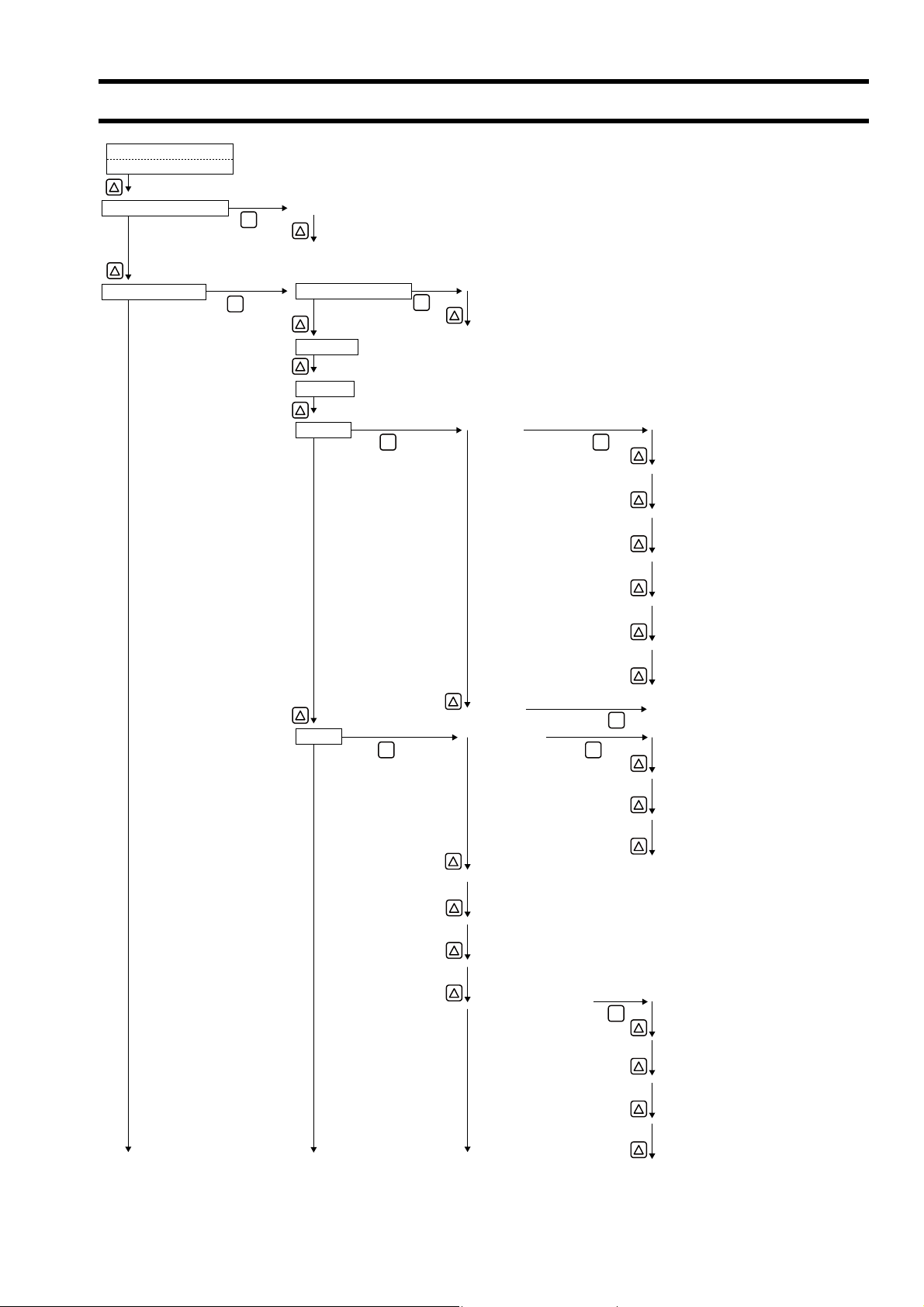
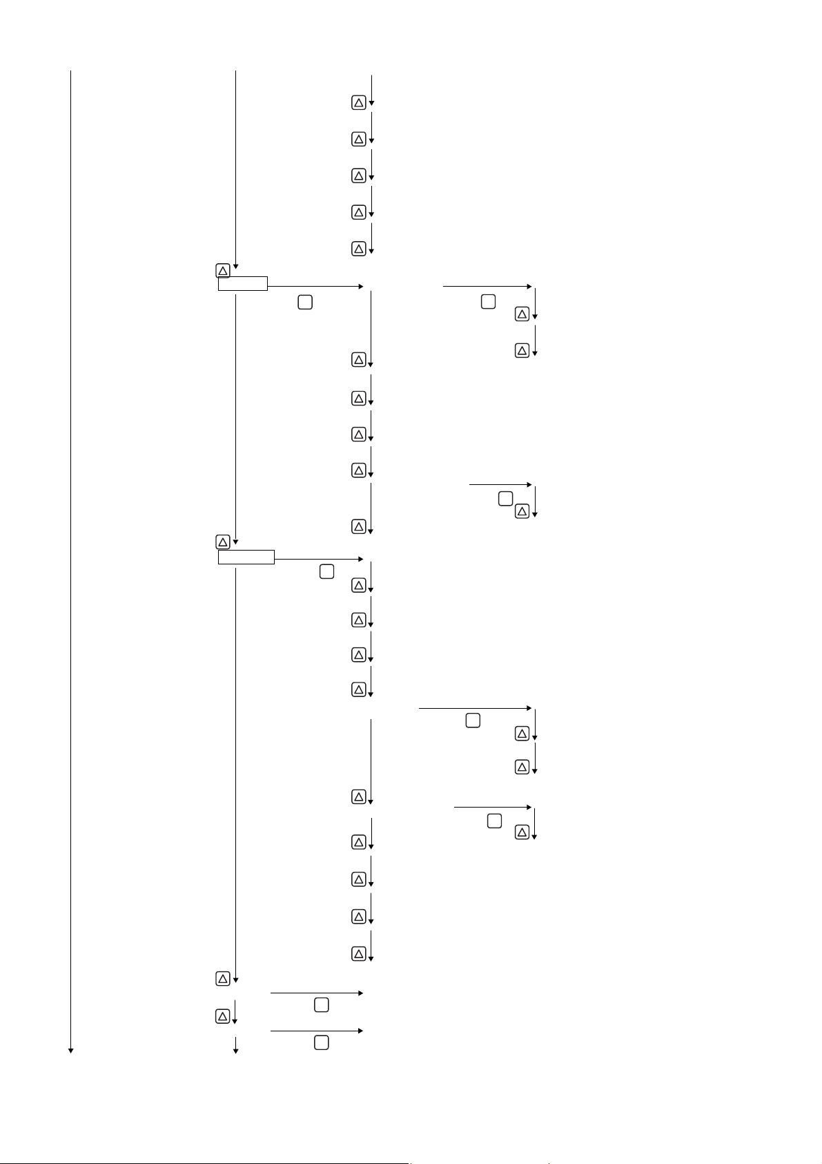
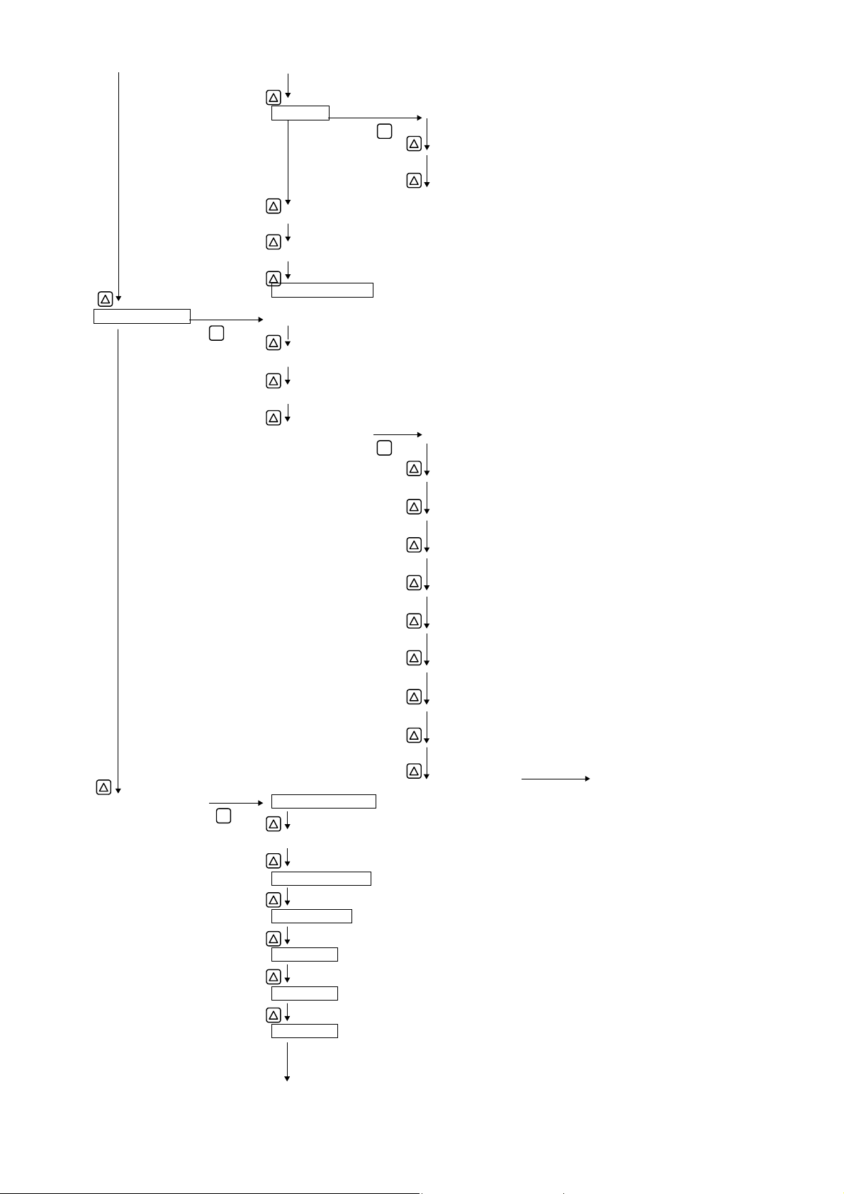
4.2. Composition of key operation
0.000 m/s
0.000 m3/h
Measurement mode
PAR.PROTECTION PROTECTION ON
ENT
PROTECTION OFF
Bulletin F-107-UXF3
OUTPUT SET ZERO ADJUSTMENT CLEAR
ENT
ENT
SET ZERO
DAMPING
CUT OFF
DISPLAY 1ST ROW VELOCITY
ENT
2ND ROW (Same as "1ST")
RANGE RANGE TYPE SINGLE
ENT ENT
ENT
FLOW RATE
FLOW RATE(%)
+TOTAL(ACTUAL)
+TOTAL PULSE
-TOTAL(ACTUAL)
-TOTAL PULSE
ENT
AUTO 2
BI-DIR
BI-DIR AUTO 2
FULL SCALE 1
FULL SCALE 2
RANGE HYS.
BURNOUT (CURRENT) NOT USED
ENT
HOLD
UPPER
LOWER
ZERO
-19-
Page 28
Bulletin F-107-UXF3
BURNOUT TIMER
OUTPUT LIMIT LOW
OUTPUT LIM.HIGH
RATE LIMIT
RATE LIMIT TIMER
TOTAL TOTAL MODE START
ENT
ENT
STOP
TOTAL RATE
TOTAL PRESET
PULSE WIDTH
BURNOUT (TOTAL) HOLD
BURNOUT TIMER
DO1 OUT NOT USED
ENT
+TOTAL PULSE
-TOTAL PULSE
FULL SCALE 2
ALARM ALL
TOTAL RESET
ENT
NOT USED
ENT
HARDWARE FAULT
FLOW SWITCH FLOW SW HIGH
TOTAL SWITCH
AO RANGE OVER
PULSE RANGE OVER
-FLOW DIRECTION
DO2 OUT (Same as "DO1 OUT")
DO3 OUT (Same as "DO1 OUT")
ENT
ENT
-20-
PROCESS ERROR
ENT
FLOW SW LOW
Page 29
DI1 INPUT NOT USED
CALIBRATION ZERO
CALIBRATION SPAN
OPERATION MODE
MEASURE SETUP SYSTEM UNIT
ENT
FLOW UNIT
TOTAL UNIT
PROCESS SETTING OUTER DIAMETER
Bulletin F-107-UXF3
ENT
TOTAL RESET
ZERO ADJUSTMENT
ENT
PIPE MATERIAL
MAINTENANCE MODE RAS INFORMATION
ENT
CURRENT
OUTPUT SETTING
TOTAL PULSE
WALL THICKNESS
LINING MATERIAL
LINING THICKNESS (Except for "NO LINING")
KIND OF FLUID
VISCOSITY
SENSOR MOUNT
SENSOR TYPE
TRANS.VOLTAGE 80Vpp (Initial value)
DO CHECK
DI CHECK
TEST MODE
-21-
Page 30
Bulletin F-107-UXF3
COMMUNICATION MODE RS-232C
ENT
ENT
RS-485
AUD RATE 9600bps
B
ENT
19200bps
38400bps
PARITY NONE
ENT
ODD
EVEN
STOP BIT 1 BIT
ENT
2 BITS
STATION No.
PROTOCOL MODBUS
ENT
M-Flow
SYSTEM LANGUAGE ENGLISH
ENT
JAPANESE
GERMAN
FRENCH
SPANISH
REGISTER ID NO.
VER. NO.
MEMORY INITIALIZE
LCD/LED CHECK
DATA DISPLAY
DETAILS TRANS.COUNT 128 (Initial value)
ENT
ENT
TRIGGER CONTROL AUTO (Initial value)
ENT
MANUAL TRIGGER LEVEL
WINDOW CONTROL AUTO (Initial value)
ENT
MANUAL U:OPEN TIME
ENT
ENT
-22-
D:OPEN TIME
Page 31

Bulletin F-107-UXF3
SATURATION 128 (Initial value)
MEAS.METHOD METHOD 1
ENT
ENT
METHOD 2 (Initial value)
METHOD 3
SIGNAL BALANCE 25% (Initial value)
TRANS.PATTERN BURST 1
ENT
ENT
BURST 2
BURST 3 (Initial value)
BURST 4
BURST 5
CHIRP 4
CHIRP 8
RESERVE
AGC GAIN AUTO (Initial value)
SIGNAL PEEK 0.125V (1024)
ENT
ENT
MANUAL U: AGC
ENT
0.25V (2048)
0.375V (3072) (Initial value)
0.5V (4096)
TRANS.WAIT TIME 5msec (Initial value)
ENT
D: AGC
-23-
Page 32

Bulletin F-107-UXF3
4.3. Parameter initial value list
Factory-set value is shown below. (When parameter setting is not provided.)
Setting unit Setting range Initial value Setting value
1 Parameter protection No. of menu: 2 PROTECTION ON PROTECTION ON, PROTECTION OFF
2 ID No 0000 to 9999 0000 ID No. is invalid when 0000 is selected.
3 Language No. of menu: 5 English *1 English, Japanese, German, French and
4 System unit No. of menu: 2 Metric Metric or inch
5 Flow unit No. of menu: 18 ft3/s gal/s, gal/min, gal/h, gal/d, kgal/d, Mgal/d, ft3/s,
6 Total unit No. of menu: 8 m
7 Outer diameter 6.00 to 6200.00mm 60.00mm [mm, in]
8 Pipe material No. of menu: 13
9 Wall thickness 0.10 to 100.00mm 4.00mm [mm, in]
10 Lining material No. of menu: 8
11 Lining thickness 0.01 to 100.00mm – [mm, in]
12 Kind of fluid No. of menu: 18
Measuring condition
13 Dynamic viscosity
14 Sensor mounting method No. of menu: 2 V method V method, Z method
15 Sensor type No. of menu: 10 – SX1-A, SX1-B, SX1-C, SX2-A, SX2-B,
16
17 Zero adjustment No. of menu: 2 Clear (unadjusted) Clear, adjustment (Clear has been factory-set.)
18 Damping 0.0 to 100.0sec 5.0sec sec
19 Low flow cut 0 to 5m/s in terms of
20 Content of display 1st
21 Decimal point position
22 Content of display 2nd
23
24 Range type No. of menu: 4 Single range Single range, Auto 2 range, Bi-dir range and
25 Full scale 1 0, ±0.3 to ±32m/s in
26 Full scale 2 0, ±0.3 to ±32m/s in
27 Hysteresis 0.00 to 20.00 10.00% %
28 Burnout (current) No. of menu: 5 Hold Not used, Hold, Lower, Upper and Zero
29 Burnout timer 0 to 900sec 10sec sec
30 Output limit low -20 to 0% -20% %
31 Output limit high 100 to 120% 120% %
32 Rate limit 0 to 5m/s in terms of
33
34 Total mode No. of menu: 3 Stop Start, Stop and Reset
35 Pulse value 0.000000 to 99999999 0m3 [(6) unit]
36 Total preset 0.000000 to 99999999 0m3 [(6) unit]
37 Pulse width No. of menu: 5 50.0msec 5.0msec, 10.0msec, 50.0msec, 100.0msec,
38 Burnout (total) No. of menu: 2 Hold Not used, hold
39
coefficient
Transmission voltage No. of menu: 4 80Vpp 20Vpp, 40Vpp, 80Vpp, 160Vpp
line
of display 1st line
Display
line
Decimal point position
of display 2nd line
Output condition
Analog output
Rate limit timer 0 to 900sec 0sec sec
Total output
Burnout timer 0 to 900sec 10sec sec
Sound velocity: 1000 to
3700m/s
Sound velocity: 1000 to
3700m/s
Sound velocity: 300 to
2500m/s
0.001 to 999.999
-6m2
/s
×10
flow velocity
No. of menu: 7 Flow velocity (m/s) Flow velocity, Flow rate, Flow rate (%), +Total
No. of menu: 7 Flow rate (m/s) Flow velocity, Flow rate, Flow rate (%), +Total
terms of flow velocity
terms of flow velocity
flow velocity
3
PVC pipe Carbon steel, stainless steel, PVC, Copper,
No lining No lining, Tar epoxy, Mortar, Rubber, TFE,
Water Seawater, dist. water, ammonia, alcohol,
1.0038
×10-6m2/s
0.150m3/h [(5) unit]
.
.
15.000m3/h [(5) unit]
0.000m3/h [(5) unit]
0.000m3/h [(5) unit]
Spanish
3
/s, ft3/min, ft3/d, kft3/d, kft /d, BBL/s, BBL/min,
ft
BBL/h, BBL/d, kBBL/d, MBBL/d
gal, kgal, ft3, kft3, Mft3, BBL, kBBL, Acre-ft
Cast iron, Aluminum, FRP, Ductile iron, PEEK,
PVDF, Acrylic, and PP
Pipe sound velocity
(Sound velocity: [m/s, ft/s])
Glass, PVC
Lining S.V. (Sound velocity: [m/s, ft/s])
benzene, bromide, ethanol, glycol, kerosene,
milk, methanol, toluol, lube oil, fuel oil, petrol
and refrigerant R410
Fluid S.V. (Sound velocity: [m/s, ft/s])
-6m2
[×10
/s, ft2/s]
Reserved (for future use)
(Actual), +Total pulse, -Total (Actual) and -Total
pulse
(Fill in the specified digit)
(Actual), +Total pulse, -Total (Actual) and -Total
pulse
(Fill in the specified digit)
Bi-dir Auto 2 range
200.0msec
3
- 24 -
Page 33

Bulletin F-107-UXF3
Setting unit Setting range Initial value Setting value
40 DO1 output type No. of output content
41 DO1 Output operation No. of menu: 2 Active ON Active ON, Active OFF
42 DO2 Output type No. of output content
43 DO2 Output operation No. of menu: 2 Active ON Active ON, Active OFF
Output condition
44 DO3 Output type No. of output content
45 DO3 Output operation No. of menu: 2 Active ON Active ON, Active OFF
46 DI1 Input type No. of input content
47 DI1 Input operation No. of menu: 2 Active ON Active ON, Active OFF
48 Zero calibration -5 to 5m/s in terms of
49 Span calibration -200.00 to 200.00% 100.00% %
50
51 Communication mode No. of menu: 2 RS-232C RS-232C, RS-485
52 Baud rate No. of menu: 3 9600bps 9600bps, 19200bps, 38400bps
53 Parity No. of menu: 3 Odd None, Odd, Even
54 Stop bit No. of menu: 2 1 bit 1 bit, 2 bits
55 Station No. 1 to 31 1 (In case of RS-485)
56
Operation mode No. of menu: 2 Standard Standard, High speed
Communication protocol No. of menu: 2 MODBUS MODBUS, Other
Communication
menu: 10
No. of alarm menu: 3
Flow switch range
0 to 32m/s in terms of
flow velocity
Total switch range
0.000000 to 99999999
menu: 10
No. of alarm menu: 3
Flow switch range
0 to 32m/s in terms of
flow velocity
Total switch range
0.000000 to 99999999
menu: 10
No. of alarm menu: 3
Flow switch range
0 to 32m/s in terms of
flow velocity
Total switch range
0.000000 to 99999999
menu: 3
flow velocity
Not used
Not used
Not used
Not used
0.000m3/h [(5) unit]
Not used
+Total pulse
-Total pulse
Range full scale 2
Alarm [All, Device error, Process error]
Flow rate switch
Flow SW high [(5) unit]
Flow SW low [(5) unit]
Total switch [(6) unit]
Range over
Pulse range over
–Flow direction
Not used
+Total pulse
-Total pulse
Range full scale 2
Alarm [All, Device error, Process error]
Flow rate switch
Flow SW high [(5) unit]
Flow SW low [(5) unit]
Total switch [(6) unit]
Range over
Pulse range over
–Flow direction
Not used
+Total pulse
-Total pulse
Range full scale 2
Alarm [All, Device error, Process error]
Flow rate switch
Flow SW high [(5) unit]
Flow SW low [(5) unit]
Total switch [(6) unit]
Range over
Pulse range over
–Flow direction
Not used
Total reset
Zero adjustment
- 25 -
Page 34

Bulletin F-107-UXF3
4.4. Parameter protection
4.4.1. Parameter protection ON/OFF
Description
Parameters can be protected so that the flow meter settings will not carelessly be changed.
z
Parameters can be protected by setting the "ID No." (Note) in the maintenance mode.
z
Note) 4 digits are factory set at "0000". (Refer to Section 4.11.8.)
Setting range: PROTECTION ON : Parameter cannot be changed.
* 1 hour after “PROTECTION OFF” is set, “PROTECTION ON” is automatically set.
* Parameter protection is set after turning power on.
For actual keying, refer to the typical operation indicated below.
Operation
(example)
Key operation Description Display
ź
ENT
ź
ź
ENT
ź
ź
ź
ź
ENT
ź
ź
ź
ENT
PROTECTION OFF : Parameter can be changed.
Change the parameter protection from ON to OFF (suppose ID No. is "2234").
Press the
PROTECTION”.
Press the
Press the
Press the
Press the
Note) If ID No. is "0000" (as factory set), press the
the parameter protection.
Enter ID No. “2234” by the
Press the
* If ID No. does not coincide, "INPUT ERROR!" appears, and the input
screen is resumed.
key in the measurement mode once to indicate “PAR.
ENT
key once to blink the 2nd line.
key once to display "PROTECTION OFF".
ENT
key once to display “PAR.PROTECTION”.
ENT
key once to indicate "0000" and blink the cursor.
ENT
key once.
ʊʊʊ Parameter protection canceled. ʊʊʊ
key or the key.
ENT
key to release
PAR.PROTECT
PAR.PROTECT
PAR.PROTECT
PAR.PROTECT
INPUT ID NO.
INPUT ID NO.
INPUT ID NO.
INPUT ID NO.
PAR.PROTECT
COMPLETE
COMPLETE
PROTECTION ON
PROTECTION ON
PROTECTION OFF
Ļ
0000
2234
Ļ
PROTECTION OFF
-26-
Page 35

Bulletin F-107-UXF3
4.5. Display language
4.5.1. How to select the language
Description
Indication language (English, Japanese, German, French, Spanish) is selectable.
z
Setting contents
English (default setting), Japanese, German, French, Spanish
For actual keying, refer to the typical operation indicated below. Set the parameter protection to OFF beforehand. (See Section 4.4.1.)
Operation
(example)
Key operation Description Display
ź
ENT
ź
ź
ENT
ź
ź
ENT
ź
ź
ź
ź
ESC
Operation
(example)
Key operation Description Display
ź
ENT
ź
ź
ENT
ź
ź
ENT
ź
ź
ź
ź
ESC
Select English for the display language.
Press the
Press the
Press the
Press the
Press the
Press the
Press the
Select Japanese for the display language.
Press the
Press the
Press the
Press the
Press the
Press the
Press the
key 4 times to display “MAINTENANCE MODE”.
ENT
key once to display “RAS INFORMATION”.
key 8 times to display “SYSTEM LANGUAGE”.
ENT
key once to blink on the 2nd line.
key 4 times to display “ENGLISH”.
ENT
key once to register.
ʊʊʊ English has been registered. ʊʊʊ
ESC
key or the key to display the measurement mode.
key 4 times to display “MAINTENANCE MODE”.
ENT
key once to display “RAS INFORMATION”.
key 8 times to display “SYSTEM LANGUAGE”.
ENT
key once to blink on the 2nd line.
key 4 times to display “JAPANESE”.
ENT
key once to register.
ʊʊʊ Japanese has been registered. ʊʊʊ
ESC
key or the key to display the measurement mode.
MAINTENANCE MODE
RAS INFORMATION
0000000000000000
SYSTEM LANGUAGE
SYSTEM LANGUAGE
SYSTEM LANGUAGE
SYSTEM LANGUAGE
SYSTEM LANGUAGE
0.000 m/s
0.000 m3/h
MAINTENANCE MODE
RAS INFORMAITION
0000000000000000
SYSTEM LANGUAGE
SYSTEM LANGUAGE
SYSTEM LANGUAGE
SYSTEM LANGUAGE
㩃㩨㩧㩄㩨
0.000 m/s
0.000 m3/h
COMPLETE
(LANGUAGE)
Ļ
㩎㨽㩥㩂
Ļ
㩐㩘㩧㩄㩨
JAPANESE
JAPANESE
ENGLISH
ENGLISH
ENGLISH
ENGLISH
JAPANESE
(JAPANESE)
-27-
Page 36

Bulletin F-107-UXF3
4.6. Checking and Setting of Piping Specifications/Detector
4.6.1. Checking piping parameter
Key operation Description Display
0.000 m/s
0.000 m3/h
ESC
ź
ENT
ź
ź
ENT
ź
ź
ź
ź
ź
ź
ź
ź
ź
Press the
Press the
Press the
Press the
Press the
Press the
Press the
Press the
Press the
Press the
Press the
Press the
Press the
measurement mode.
key 3 times to display “MEASURE SETUP”.
ENT
key once to display “SYSTEM UNIT”.
key 3 times to display “PROCESS SETTING”.
ENT
key once to display “OUTER DIAMETER”.
key once to display “PIPE MATERIAL”.
key once to display “WALL THICKNESS”.
key once to display “LINING MATERIAL”.
key once to display “KIND OF FLUID”.
key once to display “VISCOSITY”.
key once to display “SENSOR MOUNT”.
key once to display “SENSOR TYPE”.
key once to display “TRANS. VOLTAGE”.
ESC
key twice, and press the key twice to return to the
MEASURE SETUP
SYSTEM UNIT
ENGLISH
PROCESS SETTING
S= 31( 93mm)
OUTER DIAMETER
60.00 mm
PIPE MATERIAL
PVC
WALL THICKNESS
4.00 mm
LINING MATERIAL
NO LINING
KIND OF FLUID
WATER
VISCOSITY
1.003800 E-6m2/s
SENSOR MOUNT
V METHOD
SENSOR TYPE
SX1-A
TRANS. VOLTAGE
80 Vpp
0.000 m/s
0.000 m3/h
-28-
Page 37

Bulletin F-107-UXF3
4.6.2. Piping parameter setting method
Description
Set the parameters of piping and fluid to be measured to determine the sensor mounting spacing.
z
The mounting dimension of the sensor is automatically calculated. Refer to “5.1.1. Mounting of detector”.
z
CAUTION
Be sure to set the following parameters before mounting the sensor on the pipe. Mount the sensor to match the sensor
mounting length.
Unless the sensor units are spaced accurately, the measurement error will be excessive.
z
Also, the received wave may be abnormal.
z
Setting items
1. Pipe outer diameter : 6.00 to 6200.00 [mm]; 0.24 to 244 in. (factory set at 60.00 mm/2.36 in.).
2. Piping material : CARBON STEEL, STAINLESS STEEL, PVC (factory set), COPPER, CAST IRON, ALUMINIUM,
3. Wall thickness : 0.10 to 100.00 [mm] (factory set at 4.00 [mm]).
4. Lining material : NO LINING (factory set), TAR EPOXY, MORTAR, RUBBER, TEFLON, PYREX GLASS, PVC,
5. Lining thickness : 0.10 to 100.00 [mm]; 0.00394 to 3.937 [in.]
6. Measuring fluid : WATER, SEAWATER, DIST.WATER, AMMONIA, ALCOHOL, BENZENE, ETHANOL, GLYCOL,
7. Dynamic viscosity coefficient : 0.0010 to 999.999 × 10
8. Detector mounting method : V method (factory set), Z method
9. Detector type : SX1-A, SX1-B, SX1-C, SX2-A, SX2-B, Reserved
FRP, DUCTILE IRON, PEEK, PVDF, ACRYLIC, PP, Others (Sound velocity: 1000 to 3700[m/s])
Others (Sound velocity: 1000 to 3700[m/s] or 3281 to 12139 [ft/s])
KEROSENE, MILK, METHANOL, TOLUOL, LUBE OIL, FUEL OIL, PETROL, REFRIGERANT
R410, Others (Sound velocity: 300 to 2500[m/s]; 984 to 8202 [ft/s] )
-6
[m2/s]; 0.0108 to 999.999 × 10 [ft /s] (factory set at 10.8 x 10⁻⁶ [ft2/s])
2
-6
10. Transmission voltage : 20Vpp, 40Vpp, 80Vpp (factory set), 160Vpp
For actual keying, refer to the typical operation indicated below. Set the parameter protection to OFF beforehand. (See Section 4.4.1.)
Normally, select “80Vpp” for the transmission voltage.
(1) Setting method when sensor type is “SX1-A”.
Operation
(example)
Key operation Description Display
ź
ENT
ź
ź
ENT
ź
ENT
ź
Carry out setting for measuring the flow rate of water flowing through PVC pipe (for tap water).
0.000 m/s
0.000 m3/h
Press the
Press the
Press the
Press the
Press the
key 3 times to display “MEASURE SETUP”.
ENT
key once to display “SYSTEM UNIT”.
key 3 times to display “PROCESS SETTING”.
ENT
key once to display “OUTER DIAMETER”.
ENT
key once to blink the cursor.
MEASURE SETUP
SYSTEM UNIT
PROCESS SETTING
S= 16 ( 48mm)
OUTER DIAMETER
OUTER DIAMETER
METRIC
60.00 mm
0160.00 mm
0160.00 mm
0160.00 mm
0110.00 mm
0110.00 mm
Move the cursor by the
ź
the key. Operated to compose "114" because, from Piping data in
Section 7.5., the outer diameter of polyvinyl chloride pipe (tap water size)
is 114 mm.
key, and change the numeric value by
OUTER DIAMETER
114.00 mm
-29-
Page 38

Bulletin F-107-UXF3
ESC
ENT
ź
ź
ź
ź
ź
ź
ENT
ź
ź
ENT
ź
ź
ź
ź
ź
ź
ź
ESC
ź
Press the
ENT
key once to register the outer diameter.
ʊʊʊ Outer diameter has been registered. ʊʊʊ
Press the
key once to display “PIPE MATERIAL”.
Because PVC (factory set) is already registered, go to the next step.
Note) If the pipe is made of another material, press
a corresponding menu by the
Press the
Press the
key once to display “WALL THICKNESS”.
ENT
key once to blink the cursor.
Move the cursor by the
key, and change the numeric value by the
key.
ENT
key, and select
key.
Operated to compose "7" because, from Piping data in Section 7.5., the
wall thickness of polyvinyl chloride pipe (tap water size) is 7.0mm.
Press the
ENT
key once to register the wall thickness.
ʊʊʊ Wall thickness has been registered. ʊʊʊ
Press the
key once to display “LINING MATERIAL”.
"NO LINING" (factory set) is already registered. Because there is no
lining, go to the next step.
Note) If lining is provided, press the
ENT
key and key to select the
material or enter the sound velocity. Further, go to "LINING
THICKNESS", and input a lining thickness. Nothing is indicated in
case of "NO LINING".
Press the
key once to display "KIND OF FLUID". Because
"WATER" (factory set) is already registered, go to the next step.
Note) If fluid to be measured is other than water, press the
ENT
key, and
select the menu or enter the sound velocity.
Press the
Input the kinematic viscosity of the fluid to be measured.
Because the kinematic viscosity 1.0038E
key once to display "VISCOSITY".
-6
[m2/s] of water at 20°C is
already registered, go to the next step.
In case of fluid other than water, input the kinematic viscosity at a
measurement status of fluid to be measured referring to data in Section
7.5., etc.
ESC
Press the
key once to display “PROCESS SETTING”.
“S=31” is indicated on the 2nd line.
After mounting the frames on piping, insert into it 2 sensor units spaced
at 31 divisions.
Press the
ESC
key once and the key twice to return to the
measurement mode.
OUTER DIAMETER
COMPLETE
Ļ
OUTER DIAMETER
PIPE MATERIAL
WALL THICKNESS
WALL THICKNESS
WALL THICKNESS
WALL THICKNESS
COMPLETE
Ļ
WALL THICKNESS
LINING MATERIAL
KIND OF FLUID
VISCOSITY
1.0038 E-6m2/s
PROCESS SETTING
S= 31 ( 93mm)
0.000 m3/h
0.000 m3
114.00 mm
PVC
4.00 mm
004.00 mm
004.00 mm
007.00 mm
7.00 mm
NO LINING
WATER
-30-
Page 39

Bulletin F-107-UXF3
(2) Setting method when sensor type is SX1-A, SX1-B, SX1-C, SX2-A, SX2-B
Operation
(example)
Key operation Description Display
ź
ENT
ź
ź
ENT
ź
ź
ENT
ź
ź
ENT
ź
ź
ź
ź
ESC
ź
ESC
Carry out setting for measuring the flow rate of water flowing through PVC pipe (for tap water) having 100 mm of
nominal diameter, using SX2-A detector.
Press the
Press the
Press the
Press the
Press the
Press the
Press the
Press the
Press the
key 3 times to display “MEASURE SETUP”.
ENT
key once to display “SYSTEM UNIT”.
key 3 times to display “PROCESS SETTING”.
ENT
key once to display “OUTER DIAMETER”.
key 7 times to blink the cursor.
ENT
key once to blink the cursor.
key multiple times to display “SX2-A” on the 2nd line.
ENT
key once to register “SX2-A”.
ʊʊʊ “SX2-A” has been registered. ʊʊʊ
ESC
key once to display “PROCESS SETTING”.
MEASURE SETUP
SYSTEM UNIT
PROCESS SETTING
S= 31 ( 93mm)
OUTER DIAMETER
SENSOR TYPE
SENSOR TYPE
SENSOR TYPE
SENSOR TYPE
COMPLETE
SENSOR TYPE
PROCESS SETTING
S= 76.30mm
“S=76.30mm” is displayed on the 2nd line.
Align the sensor mounting spacing to 76.3mm, and attach the sensor to
the pipe.
Press the
ESC
key once and the key twice to return to the
0.000 m3/h
0.000 m3
measurement mode.
METRIC
114.00 mm
SX1-A
SX1-A
SX2-A
Ļ
SX2-A
- 31 -
Page 40

Bulletin F-107-UXF3
4.7. Zero Adjustment
Description
Zero point is calibrated.
z
Settable range:
CLEAR : Clears the zero point calibration value to "0".
SET ZERO : A point where "SET ZERO" is set will be regarded as zero flow. The flow should be stopped with a full pipe condition
For actual keying, refer to the typical operation indicated below. Set the parameter protection to OFF beforehand. (See Section 4.4.1.)
Used in case the flow cannot be stopped when calibrating the zero point.
Note 1) Where possible, stop the flow and carry out "SET ZERO" stated below.
Otherwise, an error may occur in the zero point.
when calibrating the zero point.
Note 2) The flow must completely be stopped.
Otherwise, the actual flow rate value upon completing "set zero" becomes a constant reading offset error .
It takes ten seconds to several tens of seconds to complete adjustment, depending on pipe diameter.
Operation
(example)
Key operation Description Display
ź
ENT
ź
ź
ENT
ź
ź
ź
ź
ESC
Completely fill the piping, close the upstream and downstream valves, and proceed to zero point calibration.
Press the
Press the
cursor.
Press the
Press the
* Be sure to completely stop the flow beforehand.
Press the
measurement mode.
key twice to display “OUTPUT SETTING”.
ENT
key twice to display “ZERO ADJUSTMENT” and blink the
key once, and select “SET ZERO”.
ENT
key once to carry out “SET ZERO”.
ʊʊʊ Zero adjustment has been completed. ʊʊʊ
ESC
key once, and the key 3 times to enter the
OUTPUT SETTING
ZERO ADJUSTMENT
ZERO ADJUSTMENT
ZERO ADJUSTMENT
ZERO ADJUSTMENT
0.000 m/s
0.000 m3/h
COMPLETE
Ļ
CLEAR
SET ZERO
SET ZERO
-32-
Page 41

Bulletin F-107-UXF3
4.8. Setting of unit
4.8.1. How to set the unit system
Description
Measurement unit can be selected from metric or inch system.
z
Metric system (factory set)
z
Length············································· mm, inch
Flow velocity ···································m/s, ft/s
Flow rate ········································· L/s, L/min, L/h, L/d, kL/d, ML/d, m
Total unit ········································· mL, L, m
gal/s, gal/min, gal/h, gal/d, kgal/d, Mgal/d, ft /s, ft /min, ft /d, kft /d, Mft /d, barrels (BBL units)
Kinematic viscosity coefficient ········ E
3
, km3, Mm3, gal, kgal, ft , kft , Mft , Acre-ft, mBBL, BBL, kBBL
-6m2
/s, E ft /s
2
<Note> When setting, stop status should be set at total mode. (See Section 4.9.2.)
For actual keying, refer to the typical operation indicated below. Set the parameter protection to OFF beforehand. (See Section 4.4.1.)
3
/s, m3/min, m3/h, m3/d, km3/d, Mm3/d, metric barrels (BBL units)
333
33333
Operation
Change the unit system from inch system to metric system.
(example)
Key operation Description Display
Press the
key 3 times to display “MEASURE SETUP”.
MEASURE SETUP
ź
ENT
Press the
ENT
key once to display “SYSTEM UNIT”.
SYSTEM UNIT
ź
ENT
Press the
ENT
key once to blink the cursor.
SYSTEM UNIT
ź
Press the
key once to display “METRIC”.
SYSTEM UNIT
ź
ENT
ź
ź
ź
Press the
ENT
key once to register.
ʊʊʊ METRIC has been registered. ʊʊʊ
SYSTEM UNIT
COMPLETE
SYSTEM UNIT
Ļ
ź
ESC
Press the
ESC
key once and key twice to return to the measurement
0.000 %
0.000 m3/h
mode.
INCH
INCH
METRIC
METRIC
-33-
Page 42

Bulletin F-107-UXF3
4.8.2. How to set the flow rate unit
Description
Select the unit of flow rate.
z
Metric system
z
Flow rate········· L/s, L/min, L/h, L/d, kL/d, ML/d, m
kBBL/d, MBBL/d, gal/s, gal/min, gal/h, gal/d, kgal/d, Mgal/d, ft /s, ft /min, ft /d, kft /d, Mft /d, barrels (BBL units)
<Note> First, set the unit system (metric) according to Section 4.8.1.
For actual keying, refer to the typical operation indicated below. Set the parameter protection to OFF beforehand. (See Section 4.4.1.)
3
/s, m3/min, m3/h (factory set), m3/d, km3/d, Mm3/d, BBL/s, BBL/min, BBL/h, BBL/d,
33333
Operation
Set a flow rate unit to “L/min”.
(example)
Key operation Description Display
Press the
key 3 times to display “MEASURE SETUP”.
MEASURE SETUP
ź
ENT
Press the
ENT
key once to display “SYSTEM UNIT”.
SYSTEM UNIT
ź
Press the
key once to display “FLOW UNIT”.
FLOW UNIT
ź
ENT
Press the
ENT
key once to blink the cursor.
FLOW UNIT
ź
Press the
key several times to display “L/min”.
FLOW UNIT
ź
ENT
ź
ź
ź
Press the
ENT
key once to register.
ʊʊʊ “L/min” has been registered. ʊʊʊ
FLOW UNIT
FLOW UNIT
COMPLETE
Ļ
ź
ESC
Press the
ESC
key once and the key twice to return to the
0.000 m/s
0.000 L/min
measurement mode.
METRIC
m3/h
m3/h
L/min
L/min
-34-
Page 43

Bulletin F-107-UXF3
4.8.3. How to set the total unit
Description
Select the unit of total volume.
z
Metric system
z
Total unit ········· mL, L, m
3
(factory set), km3, Mm3, mBBL, BBL, kBBL, gal, kgal, ft , kft , Mft , Acre-ft
<Note> First, set the unit system (metric) according to Section 4.8.1.
When setting, stop status should be set at total mode. (See Section 4.9.2.)
For actual keying, refer to the typical operation indicated below. Set the parameter protection to OFF beforehand. (See Section 4.4.1.)
333
Operation
Set a flow rate unit to “L”.
(example)
Key operation Description Display
Press the
key㧟imes to display MEASURE SETUP.
MEASURE SETUP
ź
ENT
Press the
ENT
key once to display “SYSTEM UNIT”.
SYSTEM UNIT
ź
Press the
key once to display “TOTAL UNIT”.
TOTAL UNIT
ź
ENT
Press the
ENT
key once to blink the cursor.
TOTAL UNIT
ź
Press the
key twice to display “L”.
TOTAL UNIT
ź
ENT
ź
ź
ź
Press the
ENT
key once to register.
ʊʊʊ “L” has been registered. ʊʊʊ
TOTAL UNIT
TOTAL UNIT
COMPLETE
Ļ
ź
ESC
Press the
ESC
key once and the key twice to return to the
0.000 L
0.000 L/min
measurement mode.
METRIC
m3
m3
L
L
-35-
Page 44

Bulletin F-107-UXF3
4.9. Output Setting
4.9.1. Setting of flow rate range
4.9.1.1. Setting of flow rate range (single range)
Description
The range (full scale) of flow rate to be measured is set.
z
* The analog output (4-20mA) corresponds to the range setting.
Settable range: 0.3 to 32 [m/s]; 0.984 to 105 [ft/s] in terms of flow velocity in piping
z
* The piping parameters and FLOW UNIT must be set beforehand.
* If a value beyond the settable range is inputted, "INPUT ERROR" appears and then last
setting is resumed.
* If "piping parameters" or "FLOW UNIT" has been changed after setting the range,
recommence the range setting.
<Note> The flow rate unit is as selected by "FLOW UNIT" in the "MEASURE SETUP" mode.
(Refer to Section 4.8.2.)
For actual keying, refer to the typical operation indicated below. Set the parameter protection to OFF beforehand. (See Section 4.4.1.)
Operation
(example)
Key operation Description Display
ź
ENT
ź
ź
ENT
ź
ź
ENT
ź
ź
ź
ź
ź
ź
ź
ź
ź
ENT
ź
ź
ź
ź
ESC
Set 60m3/h to range type, SINGLE/FULL SCALE1.
* Set the piping parameters and "FLOW UNIT" beforehand.
Press the
Press the
Press the
Press the
Because SINGLE (factory set) is already registered, go to the next step.
Press the
Press the
Move the cursor by the
key.
Change the full scale to “60”.
Note) To change the decimal point position, align the cursor with a place
to change to and press the
Press the
Press the
enter the measurement mode.
key twice to display “OUTPUT SETTING”.
ENT
key to enter the “ZERO ADJUSTMENT” mode.
key 4 times to display “RANGE”.
ENT
key once to display “RANGE TYPE”.
key once to display “FULL SCALE1”.
ENT
key once to blink the cursor.
key, and change the numeric value by the
key likewise.
ENT
key once to register.
ʊʊʊ FULL SCALE1 has been registered. ʊʊʊ
ESC
key 3 times and then press the key 3 times to
20mA
Full scale 1
4mA
0 100%
OUTPUT SETTING
ZERO ADJUSTMENT
RANGE
RANGE TYPE
FULL SCALE1
FULL SCALE1
FULL SCALE1
FULL SCALE1
FULL SCALE1
0.000 m/s
0.000 m3/h
Flow rate
00015.000 m3/h
00015.000 m3/h
00065.000 m3/h
00065.000 m3/h
0000060.0 m3/h
COMPLETE
Ļ
60.000 m3/h
15.000 m3/h
SET ZERO
SINGLE
-36-
Page 45

Bulletin F-107-UXF3
4.9.1.2. Setting of analog output at error (Burnout)
Description
Determine how to set the analog output when received wave error, etc. due to device error, accidental drain of piping or entry of
z
bubbles.
Settable range
z
(1) Analog output (4-20mA) at error
HOLD (factory set) : Outputs a current value preceding the error.
UPPER : Sets analog output to upper of the output limit (over scale).
LOWER : Sets analog output to lower of the output limit (under scale).
ZERO : Outputs 4mA.
(2) BURNOUT TIMER (time from error detection to BURNOUT processing) 0 to 900 seconds (factory set at 10 sec).
* Perform BURNOUT processing as shown below.
1. LCD display······· Measured value operates with analog output.
For actual keying, refer to the typical operation indicated below. Set the parameter protection to OFF beforehand. (See Section 4.4.1.)
Operation
(example)
Set “UPPER” to BURNOUT.
Set “20sec” to BURNOUT TIMER.
* Set the piping parameters and "FLOW UNIT" beforehand.
Key operation Description Display
Press the
key twice to display “OUTPUT SETTING”.
OUTPUT SETTING
ź
ENT
Press the
ENT
key once to display “ZERO ADJUSTMENT”.
ZERO ADJUSTMENT
ź
Press the
key 4 times to display “RANGE”.
RANGE
ź
ENT
Press the
ENT
key once to display “RANGE TYPE”.
RANGE TYPE
ź
Press the
key 4 times to display “BURNOUT” (CURRENT).
BURNOUT (CURRENT)
ź
ENT
Press the
ENT
key once to blink on the 2nd line.
BURNOUT (CURRENT)
ź
Press the
key once to display “UPPER”.
BURNOUT (CURRENT)
ź
ENT
ź
ź
ź
Press the
ENT
key once to register.
ʊʊʊ UPPER has been registered. ʊʊʊ
BURNOUT (CURRENT)
COMPLETE
Ļ
BURNOUT (CURRENT)
ź
Press the
key once to display “BURNOUT TIMER”.
BURNOUT TIMER
ź
ENT
Press the
ENT
key once to blink the cursor.
BURNOUT TIMER
ź
Press the
key once to align the cursor to “1”.
BURNOUT TIMER
ź
Press the
key once to set “2”.
BURNOUT TIMER
ź
ENT
ź
ź
ź
Press the
ENT
key once to register.
ʊʊʊ BURNOUT TIMER has been registered. ʊʊʊ
BURNOUT TIMER
COMPLETE
BURNOUT TIMER
Ļ
ź
ESC
Press the
ESC
key twice and then press the key 3 times to enter
0.000 %
0.000 m3/h
the measurement mode.
SET ZERO
SINGLE
HOLD
HOLD
UPPER
UPPER
10 sec
010 sec
010 sec
020 sec
20 sec
-37-
Page 46

Bulletin F-107-UXF3
4.9.1.3. Output limit
Description
Upper and lower limits can be set within the range of analog output 0.8mA
z
to 23.2mA (-20% to 120%).
Settable range
z
(1) Output lower limit: -20% to 0% (0.8mA to 4mA)
(2) Output upper limit: 100% to 120% (20mA to 23.2mA)
For actual keying, refer to the typical operation indicated below. Set the
parameter protection to OFF beforehand. (See Section 4.4.1.)
Operation
(example)
Set “-10% (2.4mA)” to lower limit, and “110% (21.6mA)” to upper limit.
* Set the piping parameters and "FLOW UNIT" beforehand.
Lower limit
Analog output
23.2mA
20mA
4mA
-20% 100% 120%
0%
0.8mA
Key operation Description Display
Press the
key twice to display “OUTPUT SETTING”.
OUTPUT SETTING
ź
ENT
Press the
ENT
key once to display “ZERO ADJUSTMENT”.
ZERO ADJUSTMENT
ź
Press the
key 4 times to display “RANGE”.
RANGE
ź
ENT
Press the
ENT
key once to display “RANGE TYPE”.
RANGE TYPE
ź
Press the
key 6 times to display “OUTPUT LIMIT LOW”.
OUTPUT LIMIT LOW
ź
ENT
Press the
ENT
key once to blink the cursor.
OUTPUT LIMIT LOW
ź
Press the
key once to align the cursor to “2”.
OUTPUT LIMIT LOW
ź
Press the
key several times to set “1”.
OUTPUT LIMIT LOW
ź
ENT
Press the
ENT
key once to register.
OUTPUT LIMIT LOW
COMPLETE
ź
ź
ź
ʊʊʊ OUTPUT LIMIT LOW has been registered. ʊʊʊ
OUTPUT LIMIT LOW
ź
Press the
key once to display “OUTPUT LIM. HIGH”.
OUTPUT LIM. HIGH
ź
ENT
Press the
ENT
key once to blink the cursor.
OUTPUT LIM. HIGH
ź
Press the
key once to align the cursor to “2”.
OUTPUT LIM. HIGH
ź
Press the
key several times to set “1”.
OUTPUT LIM. HIGH
ź
ENT
Press the
ENT
key once to register.
OUTPUT LIM. HIGH
COMPLETE
ź
ź
ź
ʊʊʊ OUTPUT LIM. HIGH has been registered. ʊʊʊ
OUTPUT LIM. HIGH
ź
ESC
Press the
ESC
key twice and then press the key 3 times to enter
0.000 %
0.000 m3/h
the measurement mode.
Upper limit
Flow rate
SET ZERO
SINGLE
-20 %
-20 %
-20 %
-10 %
Ļ
-10 %
120 %
120 %
120 %
110 %
Ļ
110 %
-38-
Page 47

Bulletin F-107-UXF3
4.9.2. Setting the total
4.9.2.1. Setting the total pulse (pulse value, pulse width)
Description
Set to totalize a process variable (flow rate) by total meter, etc. according to total pulse output.
z
Pulse value: Total amount (volume) per pulse.
z
A pulse is outputted when the total volume has attained an amount set by the pulse value, and adds to the total pulse count (in case of
total pulse indication). Settable range: 0.000001 to 99999999
* Set the total unit before setting the pulse value. (See Section 4.8.3.)
Pulse width: Width of total pulse output.
z
Select a pulse width according to a corresponding total meter out of menus. Settable range: 5ms, 10ms, 50ms, 100ms, 200ms
Note) If the output is through DO2 (relay contact), select 50ms or longer. (See Section 4.9.3.)
Restrictions in the setup
z
Output of total pulses involves the following restrictions depending on the DO output port (DO1, DO2, DO3).
DO output port Frequency range of pulse output
Pulse width
(at full scale flow rate)
DO1, DO2: Transistor, open collector 100 pulse/sec 5ms, 10ms, 50ms, 100ms, 200ms
DO3: Relay contact 1 pulse/sec 50ms, 100ms, 200ms
The maximum output frequency is also restricted by the setup of the pulse width. Therefore, set the pulse width and pulse value so
that both of condition 1 and condition 2 indicated below are satisfied. Correct results may not occur, if any setup that does not satisfy
both of condition 1 and condition 2 is made.
Condition 1:
FULL SCALE
TOTAL RATE [m
Condition 2:
FULL SCALE
TOTAL RATE [m
(Note1)
(Note1)
[m3/s]
3
]
[m3/s]
3
]
100[Hz]
d
d
2 × PULSE WIDTH [ms]
(In case of DO1, DO2)
1[Hz]
(In case of DO3)
1000
Note 1) The range of FULL SCALE1 or FULL SCALE2, whichever is larger, is the object in the case of automatic 2-range setup,
forward and reverse range setup or forward and reverse automatic 2-range setup.
Note 2) The output frequency on the output ports is limited when the flow rate exceeds the set range. Therefore, if such a setup that
the maximum frequency per range occurs at the time of 100% flow rate, there is possibility that the total pulse output will be
incapable of following when the flow rate exceeds 100%, and accurate total value cannot be obtained if over-range continues
for a long time. If there are cases where the flow rate exceeds 100%, modify the set range and pulse value so that the
maximum frequency will not exceed the restricted level.
Example of calculation
Calculate the range that permits setup of the total value under the range and pulse width indicated below.
When the range and the pulse width are as follows.
FLOW SPAN -1: 36[m
3
/h] (=0.01[m3/s]), Pulse width:50[ms]
i) In case of DO1/DO2 output
Condition 1
TOTAL RATE t
FULL SCALE [m
100[Hz]
3
/s]
=
= 0.0001 [m
0.01 [m
100 [Hz]
3
/s]
3
] = 0.1 [L]
As above:
0.1 [L] d TOTAL RATE
··································································································································A
Condition 2
TOTAL RATE t FULL SCALE [m
2 PULSE WIDTH [ms]
3
/s] ×
1000
= 0.01 [m3/s] ×
2 50 [ms]
1000
= 0.001 [m3] = 1 [L] ·····························B
The settable range of the total value that satisfies both of condition 1 and condition 2 is as follows from results of calculation A and B.
1 [L] d TOTAL RATE
ii) In case of DO3 output
Condition 1
TOTAL RATE t
FULL SCALE [m
1 [Hz]
3
/s]
=
0.01 [m
1 [Hz]
3
/s]
= 0.01 [m3] = 10 [L] ········································································C
Condition 2 is same as that of the case of DO1 output indicated above.
Therefore, the settable range of the total value is as follows from results of calculation B and C.
10 [L] d PULSE VALUE d 864 [m
3
]
Note) When the total setting value is “0”, total pulse is not output.
Note) When setting, stop status is set at the total mode.
For actual keying, refer to the typical operation indicated below. Set the parameter protection to OFF beforehand. (See Section 4.4.1.)
-39-
Page 48

Bulletin F-107-UXF3
Operation
(example)
Set total value to 0.1m3/pulse, and pulse width to 100ms.
* Set the total value beforehand.
Key operation Description Display
Press the
key twice to display “OUTPUT SETTING”.
OUTPUT SETTING
ź
ENT
Press the
ENT
key once to display “ZERO ADJUSTMENT”.
ZERO ADJUSTMENT
ź
Press the
key 5 times to display “TOTAL”.
TOTAL
ź
ENT
Press the
ENT
key once to display “TOTAL MODE”.
TOTAL MODE
ź
Press the
key once to display “TOTAL RATE”.
TOTAL RATE
ź
ENT
Press the
ENT
key once to display the cursor.
TOTAL RATE
000000000 m3
ź
Press the
key 7 times to move the cursor.
TOTAL RATE
000000000 m3
ź
Press the
key several times to display decimal point.
TOTAL RATE
0000000.0 m3
ź
Press the
key once to move the cursor.
TOTAL RATE
0000000.0 m3
ź
Press the
key once to display “1”.
TOTAL RATE
0000000.1 m3
ź
ENT
ź
ź
ź
ź
Press the
Press the
ENT
key once to register.
ʊʊʊ TOTAL RATE has been registered. ʊʊʊ
key twice to display “PULSE WIDTH”.
TOTAL RATE
COMPLETE
TOTAL RATE
PULSE WIDTH
Ļ
0.1 m3
ź
ENT
Press the
ENT
key once to blink the cursor.
PULSE WIDTH
ź
Press the
key twice, and select “100.0msec”.
PULSE WIDTH
ź
ENT
ź
ź
ź
Press the
ENT
key once to register.
ʊʊʊ PULSE WIDTH has been registered. ʊʊʊ
PULSE WIDTH
COMPLETE
PULSE WIDTH
Ļ
ź
Press the
key 3 times to display “TOTAL MODE”.
TOTAL MODE
ź
ENT
Press the
ENT
key once to blink the cursor.
TOTAL MODE
ź
Press the
key once, and select “TOTAL PRESET”.
TOTAL MODE
ź
ENT
ź
ź
ź
Press the
ENT
key once to register.
ʊʊʊ TOTAL MODE has been registered. ʊʊʊ
TOTAL MODE
COMPLETE
TOTAL MODE
Ļ
ź
ESC
Press the
ESC
key twice and then press the key 3 times to enter
0.000 %
0.000 m3/h
the measurement mode.
SET ZERO
STOP
0 m3
50.0 msec
50.0 msec
100.0 msec
100.0 msec
STOP
STOP
TOTAL PRESET
TOTAL PRESET
-40-
Page 49

4.9.2.2. Setting the preset value
Description
Preset value: Value which appears on the total counter when the total value has been reset.
z
Settable range:0 to 99999999
<Note> A resetting action simultaneously resets both forward total memory and reverse total memory.
Set the total unit beforehand in the MEASURE SETUP mode. (Refer to 4.8.3.)
When setting, stop status is set at the total mode.
Bulletin F-107-UXF3
Total value
Reset
Reset
Reset
Preset value
Time
For actual keying, refer to the typical operation indicated below. Set the parameter protection to OFF beforehand. (See Section 4.4.1.)
Operation
(example)
Set the preset value to 100m3.
* Set the total unit beforehand.
Key operation Description Display
Press the
key twice to display “OUTPUT SETTING”.
OUTPUT SETTING
ź
ENT
Press the
ENT
key once to display “ZERO ADJUSTMENT”.
ZERO ADJUSTMENT
SET ZERO
ź
Press the
key 5 times to display “TOTAL”.
TOTAL
ź
ENT
Press the
ENT
key once to display “TOTAL MODE”.
TOTAL MODE
STOP
ź
Press the
key twice to display “TOTAL PRESET”.
TOTAL PRESET
0 m3
ź
ENT
Press the
ENT
key once to display the cursor.
TOTAL PRESET
00000000 m3
ź
Press the
ź
* Note that, it cannot be entered on the first digit (leftmost).
Press the
key 6 times to move the cursor.
key once to display “1”.
TOTAL PRESET
00000000 m3
TOTAL PRESET
00000100 m3
ź
ENT
ź
ź
ź
ź
Press the
ENT
key once to register.
ʊʊʊ “TOTAL PRESET” has been registered. ʊʊʊ
Press the
key 4 times to display “TOTAL MODE”.
TOTAL PRESET
COMPLETE
TOTAL PRESET
TOTAL MODE
Ļ
100 m3
STOP
ź
ENT
Press the
ENT
key once to blink the cursor.
TOTAL MODE
STOP
ź
Press the
key once, and select “TOTAL PRESET”.
TOTAL MODE
TOTAL PRESET
ź
TOTAL MODE
COMPLETE
Ļ
TOTAL MODE
TOTAL PRESET
0.000 %
0.000 m3/h
ESC
ENT
ź
ź
ź
ź
Press the
Press the
ENT
key once to register.
ʊʊʊ “TOTAL MODE” has been registered. ʊʊʊ
ESC
key twice and then press the
key 3 times to enter
the measurement mode.
-41-
Page 50

Bulletin F-107-UXF3
4.9.2.3. TOTAL mode (total reset, start, stop)
Description
The total is started, stopped or reset.
z
Settable range: START, STOP, TOTAL RESET
z
START : Starts totalizing. Totalizes continuously from the stopped status.
STOP : Stops totalizing. Setting cannot be changed when it is not stopped.
RESET : Resets the total memory to the preset value, and starts totalizing.
<Note> A resetting action simultaneously resets both forward total memory and reverse total memory.
For actual keying, refer to the typical operation indicated below. Set the parameter protection to OFF beforehand. (See Section 4.4.1.)
Operation
Reset the total value (preset value 0m3), and restart a total.
(example)
Key operation Description Display
0.00 m3/h
+ 127.26 m3
Press the
key twice to display “OUTPUT SETTING”.
OUTPUT SETTING
ź
ENT
Press the
ENT
key once to display “ZERO ADJUSTMENT”.
ZERO ADJUSTMENT
ź
Press the
key 5 times to display “TOTAL”.
TOTAL
ź
ENT
Press the
ENT
key once to display “TOTAL MODE”.
TOTAL MODE
ź
ENT
Press the
ENT
key once to blink the cursor.
TOTAL MODE
ź
Press the
key twice to display “TOTAL RESET”.
TOTAL MODE
ź
ENT
ź
ź
ź
Press the
ENT
key twice to execute “TOTAL RESET”.
ʊʊʊ The total operation is started. ʊʊʊ
TOTAL MODE
COMPLETE
TOTAL MODE
Ļ
ź
ESC
Press the
ESC
key twice and then press the key 3 times to enter
0.00 m3/h
0.00 m3
the measurement mode.
SET ZERO
START
START
TOTAL PRESET
TOTAL PRESET
-42-
Page 51

Bulletin F-107-UXF3
4.9.2.4. Determining how to dispose of total at error (BURNOUT)
Description
BURNOUT (TOTAL)
Determines how to dispose of the total when the measurement status is abnormal on account of an empty pipe interior or bubbles
z
mixed in fluid (common to total indication and total pulse output).
Settable range:
z
HOLD : Stops the total (as factory set).
NOT USED : Continues the total according to a flow rate marked immediately before the error occurrence.
BURNOUT TIMER
Sets the time from error occurrence to error processing.
z
Settable range: 0 to 900sec (factory set: 10sec)
z
The total continues until the burnout timer is actuated.
For actual keying, refer to the typical operation indicated below. Set the parameter protection to OFF beforehand. (See Section 4.4.1.)
Operation
(example)
Change the processing from "BURNOUT" to "HOLD", and change the burnout timer setting from 10 seconds to 15
seconds.
Key operation Description Display
Press the
key twice to display “OUTPUT SETTING”.
OUTPUT SETTING
ź
ENT
Press the
ENT
key once to display “ZERO ADJUSTMENT”.
ZERO ADJUSTMENT
ź
Press the
key 5 times to display “TOTAL”.
TOTAL
ź
ENT
Press the
ENT
key once to display “TOTAL MODE”.
TOTAL MODE
ź
Press the key 4 times to display “BURNOUT(TOTAL)”.
ź
Because HOLD (factory set) is already registered, go to the next step.
BURNOUT(TOTAL)
ź
ź
ź
Note) For setting “NOT USED”, press the key, and the key to
select “NOT USED”.
Press the
key once to display “BURNOUT TIMER”.
ENT
BURNOUT TIMER
ź
ENT
Press the
ENT
key once to blink the cursor.
BURNOUT TIMER
ź
Press the
key twice to move the cursor.
BURNOUT TIMER
ź
Press the
key 5 times to set “5”.
BURNOUT TIMER
ź
ENT
ź
ź
ź
Press the
ENT
key once to register.
ʊʊʊ BURNOUT TIMER has been registered. ʊʊʊ
BURNOUT TIMER
COMPLETE
BURNOUT TIMER
Ļ
ź
ESC
Press the
ESC
key twice and then press the key 3 times to enter
0.00 m3/h
+ 0.00 m3
the measurement mode.
SET ZERO
START
HOLD
10sec
010sec
010sec
015sec
15sec
-43-
Page 52

Bulletin F-107-UXF3
4.9.3. Setting the DO output
Description
Selects the output of total pulses and statuses (of alarm, flow switch, total switch, etc.).
z
Settable range (common to DO1, DO2 and DO3)
z
NOT USED : Does not use the contact output.
+TOTAL PULSE : Outputs the forward total pulses.
-TOTAL PULSE : Outputs total pulse in reverse direction.
FULL SCALE 2 : Selects a contact output as FULL SCALE 2 measurement status.
ALARM
ALL : Selects a contact output at HARDWARE FAULT or PROCESS ERROR status.
HARDWARE FAULT : Selects a contact output when circuit error such as memory occurred.
PROCESS ERROR : Selects a contact output when no waves are received, or waves are unstable.
FLOW SWITCH
FLOW SW HIGH : Selects a contact output when flow rate is above the setting.
FLOW SW LOW : Selects a contact output when flow rate is below the setting.
TOTAL SWITCH : Selects a contact output when total value exceeds the setting.
AO RANGE OVER : Selects a contact output when the lower and upper limits of range are above the setting.
PULSE RANGE OVER : Selects a contact output when the total pulse output exceeds the maximum output frequency.
-FLOW DIRECTION : Selects a contact output when the flow is in reverse direction.
CONTACT ACTION
ACTIVE ON : Normally off (DO1/DO2) or normal open (DO3).
ACTIVE OFF : Normally on (DO1/DO2) or normal close (DO3).
(forward automatic 2 ranges, forward and reverse range, forward/reverse automatic 2 ranges)
CAUTION
If the contact action is set to “ACTIVE OFF”, DO output is provided when the power is turned on.
z
Check if DO output can be modified before setting.
z
<Note> DO output specifications
For actual keying, refer to the typical operation indicated below. Set the parameter protection to OFF beforehand. (See Section 4.4.1.)
DO1/DO2 : Open collector, Contact capacity 30V DC, 0.1A
When total pulse output is selected (Note: See 4.9.2.1)
100 pulses/s or less (at full scale flow rate)
Pulse width: 5, 10, 50, 100 or 200ms.
DO3 : Relay contact, Contact capacity 220V AC/30V DC, 1A
Service life 200,000 times (under rated load), Can be replaced if provided with a socket. (See 6.4. How to
replace the relay)
When total pulse output is selected (Note: See 4.9.2.1)
1 pulse/s or less (at full scale flow rate)
Pulse width: 50, 100 or 200ms.
4.9.3.1. How to validate the total pulse output
Description
Validates the total pulse output for DO1 OUT, DO2 OUT and/or DO3 OUT.
z
+TOTAL PULSE : Outputs flow rate total pulse in forward direction.
-TOTAL PULSE : Reverse flow rate total pulse output.
Note) Referring to Section 4.9.2.1., set the pulse value, pulse width, etc.
For concrete keying, refer to the typical operation indicated below. Set the parameter protection to OFF beforehand. (See Section 4.4.1.)
Operation
(example)
Key operation Description Display
ź
ENT
ź
ź
Set the DO1 output to “+ TOTAL PULSE”.
Also, set the contact to “ACTIVE ON”.
Press the
Press the
Press the
* Press the
key twice to display “OUTPUT SETTING”.
ENT
key once to display “ZERO ADJUSTMENT”.
key 6 times to display “DO1 OUT”.
key again to display “DO2 OUT”.
OUTPUT SETTING
ZERO ADJUSTMENT
SET ZERO
DO1 OUT
NOT USED
ENT
ź
* Press the
Press the
key once again to display “DO3 OUT”.
ENT
key once to blink the cursor.
DO1 OUT
NOT USED
-44-
Page 53

Bulletin F-107-UXF3
ESC
ź
ENT
ź
ź
ź
ź
ENT
ź
ENT
ź
ź
ź
ź
Press the
Press the
Press the
key once to display “+TOTAL PULSE” on the 2nd line.
key again to select “-TOTAL PULSE”.
ENT
key once to register “+TOTAL PULSE”.
ʊʊʊ “+TOTAL PULSE” has been registered. ʊʊʊ
ENT
Press the
Press the
* To select normally on, press the
key once to display “CONTACT ACTION”.
ENT
key once to register “ACTIVE ON” (normally off).
key.
ʊʊʊ “ACTIVE ON” has been registered. ʊʊʊ
Press the
ESC
key twice and then press the key 3 times to enter
the measurement mode.
DO1 OUT
+TOTAL PULSE
DO1 OUT
COMPLETE
Ļ
STATUS OUT
CONTACT ACTION
CONTACT ACTION
CONTACT ACTION
COMPLETE
Ļ
STATUS OUT
CONTACT ACTION
0.000 %
0.000 m3/h
ACTIVE ON
-45-
Page 54

Bulletin F-107-UXF3
4.9.4. Setting the LCD indication
Description
Flow velocity indication
z
Selectable flow velocity units: m/s (if SYSTEM UNIT was set to METRIC) (See 4.8.1)
<Note> The decimal point position is fixed. (Decimal point 3 digits)
Flow rate indication
z
Selectable flow rate indications: Actual value reading, % reading.
<Note> The indication unit is as selected by FLOW UNIT. (See 4.8.2.)
Total indication
z
Selectable total indications: Actual total value reading (forward/reverse flow), total pulse count (forward/reverse flow).
<Note> The indication unit is as selected by TOTAL UNIT. (See 4.9.4.)
How to validate the indication
z
Set the DISPLAY setting mode to 1st ROW (for indication on 1st line) or 2nd ROW (for indication on 2nd line), and further select
indication contents.
For actual keying, refer to the typical operation indicated below. Set the parameter protection to OFF beforehand. (See Section 4.4.1.)
Operation
(example)
Key operation Description Display
ź
ENT
ź
ź
ENT
ź
ENT
ź
ź
ENT
ź
ź
ENT
ź
ź
ź
ź
ESC
Display the 1st line of LCD indication in percentages (%).
Press the
Press the
Press the
Press the
Press the
Press the
Press the
“1:DECIMAL POINT”.
Press the
Press the
Press the
the measurement mode.
key twice to display “OUTPUT SETTING”.
ENT
key once to display “ZERO ADJUSTMENT”.
key 3 times to display “DISPLAY”.
ENT
key once to blink the cursor.
ENT
key again, and select “1ST LOW”.
key twice to display “FLOW RATE(%)”.
ENT
key once, and select and fix “FLOW RATE(%)” to display
key once to shift the decimal point position to next place.
ENT
key once to register.
ʊʊʊ FLOW RATE(%) indication has been set. ʊʊʊ
ESC
key twice and then press the key 3 times to enter
OUTPUT SETTING
ZERO ADJUSTMENT
DISPLAY
DISPLAY
1ST LOW
1ST LOW
1:DECIMAL POINT
.
1:DECIMAL POINT
.
1:DECIMAL POINT
1:DECIMAL POINT
.
0.00 %
0.000 m3/h
COMPLETE
Ļ
SET ZERO
DISPLAY 1
DISPLAY 1
VELOCITY
FLOW RATE(%)
-46-
Page 55

Bulletin F-107-UXF3
4.9.5. Setting the damping
Description
Used for attenuating the variation of measured value.
z
A time constant is set (response time of about 63%).
Settable range: 0.0 to 100.0sec in 0.1 sec steps
Note) In case you set to 0 sec, response time becomes as below.
System cycle 0.2sec
x
Dead time 0.2sec or less, time constant 0.1sec
x
For actual keying, refer to the typical operation indicated below. Set the parameter protection to OFF beforehand. (See Section 4.4.1.)
Operation
(example)
Key operation Description Display
ź
ENT
ź
ź
ENT
ź
ź
ENT
ź
ź
ź
ź
ESC
Change the damping from 5 to 20 sec.
Press the
Press the
Press the
Press the
Set “20” by the
Press the
Press the
the measurement mode.
key twice to display “OUTPUT SETTING”.
ENT
key once to display “ZERO ADJUSTMENT”.
key once to display “DAMPING”.
ENT
key once to blink the cursor.
key and the key.
ENT
key once to register.
ʊʊʊ DAMPING has been registered. ʊʊʊ
ESC
key once and then press the key 3 times to enter
OUTPUT SETTING
ZERO ADJUSTMENT
DAMPING
DAMPING
DAMPING
DAMPING
DAMPING
0.000 m/s
0.000 m3/h
COMPLETE
Ļ
SET ZERO
5.0 sec
005.0 sec
005.0 sec
025.0 sec
025.0 sec
020.0 sec
20 sec
-47-
Page 56

Bulletin F-107-UXF3
4.9.6. Setting the low flow rate cutting
Description
The output can be cut when the flow rate is too small.
z
Effective for indication, analog output (4-20mA) and total operation.
z
Settable range: 0 to 5 [m/s]; 0 to 16.4 [ft/s] in terms of flow velocity.
(Factory set: 0.150 [m
3
/h]; 5.3 [ft /h])
3
Output
Note 1) As required, set the low flow rate cut because the flow meter may read a
flow rate when the fluid in the piping is moving on account of convection,
etc. even if the valves are closed.
Note 2) The flow rate unit is as selected by "FLOW UNIT" in "MEASURE SETUP".
(See 4.8.2.)
For actual keying, refer to the typical operation indicated below. Set the parameter
protection to OFF beforehand. (See Section 4.4.1.)
Low flow cut setting value
Operation
Set the low flow rate cut point to 0.5 [m3/h].
(example)
Key operation Description Display
Press the
key twice to display “OUTPUT SETTING”.
OUTPUT SETTING
ź
ENT
Press the
ENT
key once to display “ZERO ADJUSTMENT”.
ZERO ADJUSTMENT
ź
Press the
key twice to display “CUT OFF”.
CUT OFF
ź
ENT
Press the
ENT
key once to blink the cursor.
CUT OFF
0000.150 m3/h
ź
0000.150 m3/h
Flow rate
SET ZERO
0.150 m3/h
ESC
ź
ENT
ź
ź
ź
ź
Set “0.5” by the
Press the
ENT
key and the key.
key once to register.
ʊʊʊ CUT OFF has been registered. ʊʊʊ
Press the
ESC
key once and then press the key 3 times to enter
the measurement mode.
0000.550 m3/h
0000.550 m3/h
CUT OFF
0000.500 m3/h
CUT OFF
COMPLETE
Ļ
CUT OFF
0.500 m3/h
0.000 m/s
0.000 m3/h
-48-
Page 57

4.10. Application operation of parameter
4.10.1. Setting automatic 2 ranges
Description
The function carries out a measurement while changing over the range
z
according to the flow rate.
The current output changes with the action range as illustrated on the right.
z
The hysteresis can be set to between 0 and 20% of the smaller range.
z
Upon setting DO1, DO2 or DO3 to "FULL SCALE 2", a contact outputs "FULL
z
SCALE 2" action. Select “ACTIVE ON” or “ACTIVE OFF” separately. (See
4.10.5.)
Settable range: 0.3 to 32 [m/s]; 0.984 to 105 [ft/s] in terms of flow velocity for
z
FULL SCALE1 and FULL SCALE2.
* Preset PIPE PARAMETER
* If a value beyond the settable range is inputted, "INPUT ERROR" appears
and then last setting is resumed.
* If "FLOW UNIT" has been changed after setting the range, redo the range
setting.
* When FULL SCALE2 is not used (in the case of single range), set “0” to
FULL SCALE2.
and FLOW UNIT.
Bulletin F-107-UXF3
20mA
FULL SCALE1
FULL SCALE2
4mA
Hysteresis
<Note> The flow rate unit is as selected by "FLOW UNIT". Before setting range, set the "FLOW UNIT".
For actual keying, refer to the typical operation indicated below. Set the parameter protection to OFF beforehand. (See Section 4.4.1.)
Operation
(example)
Key operation Description Display
ź
ENT
ź
ź
ENT
ź
ź
ENT
ź
ź
ENT
ź
ź
ź
ENT
ź
ź
ź
ź
ź
Set “AUTO 2” to “RANGE TYPE”, 10[m3/h] to “FULL SCALE1”, and 60[m3/h] to “FULL SCALE2”.
Set “RANGE HYS.” to 7%.
* Preset “PIPE PARAMETER” and “FLOW UNIT”.
Press the
Press the
Press the
Press the
Press the
Press the
Press the
Press the
Press the
Press the
Note) To change the decimal point position, align the cursor with a place
to change to, and press the
Press the
Press the
key twice to display “OUTPUT SETTING”.
ENT
key once to display “ZERO ADJUSTMENT”.
key 4 times to display “RANGE”.
ENT
key twice to blink the cursor.
key once, and select “AUTO 2”.
ENT
key once to display “RANGE TYPE”.
key once to display “FULL SCALE1”.
ENT
key once to blink the cursor on the 2nd line.
key several times to align the cursor to “2”.
key several times to change to “1”.
key.
ENT
key once to register.
ʊʊʊ FULL SCALE1 has been registered. ʊʊʊ
key once to display “FULL SCALE2”.
(See 4.8.2.)
OUTPUT SETTING
ZERO ADJUSTMENT
RANGE
RANGE TYPE
RANGE TYPE
RANGE TYPE
FULL SCALE1
FULL SCALE1
FULL SCALE1
FULL SCALE1
FULL SCALE1
FULL SCALE1
FULL SCALE2
20.0000 m3/h
0020.0000 m3/h
0020.0000 m3/h
0010.0000 m3/h
COMPLETE
Ļ
10.0000 m3/h
0.0000 m3/h
SET ZERO
SINGLE
AUTO 2
AUTO 2
-49-
Page 58

Bulletin F-107-UXF3
ESC
ENT
ź
ź
ź
ENT
ź
ź
ź
ź
ź
ENT
ź
ź
ź
ENT
ź
ź
ź
ź
ENT
Press the
Press the
Press the
Press the
key once to blink the cursor.
key twice to move the cursor.
key 6 times to set “6”.
ENT
key once to register.
ʊʊʊ FULL SCALE2 has been registered. ʊʊʊ
Press the
Press the
Press the
Press the
Press the
key once to display “RANGE HYS.”.
ENT
key once to blink the cursor.
key once to move the cursor.
key twice to set “7”.
ENT
key once to register.
ʊʊʊ RANGE HYS. has been registered. ʊʊʊ
Press the
ESC
key twice and then press the key 3 times to enter
the measurement mode.
FULL SCALE2
0000.0000 m3/h
FULL SCALE2
0000.0000 m3/h
FULL SCALE2
0060.0000 m3/h
FULL SCALE2
COMPLETE
Ļ
FULL SCALE2
60.0000 m3/h
RANGE HYS.
5.00 %
RANGE HYS.
05.00 %
RANGE HYS.
05.00 %
RANGE HYS.
07.00 %
RANGE HYS.
COMPLETE
Ļ
RANGE HYS.
7.00 %
0.000 %
0.000 m3/h
-50-
Page 59

4.10.2. Setting the Bi-directional range
Bulletin F-107-UXF3
Description
The function measures the flow rate of either forward or reverse flow while changing
z
over the range corresponding to the flow direction.
The current output changes with the action range as illustrated on the right.
z
The hysteresis can be set to between 0 and 20% of the action range.
z
Upon setting DO1, DO2 or DO3 to "FULL SCALE2", a contact outputs "FULL
z
SCALE2" action.
Select “ACTIVE ON” or “ACTIVE OFF” separately. (See 4.10.5.)
Settable range: ±0.3 to 32[m/s]; 0.984 to 105 [ft/s] in terms of flow velocity for FULL
z
SCALE1 and FULL SCALE2.
* Preset PIPE PARAMETER and FLOW UNIT.
* If a value beyond the settable range is inputted, "INPUT ERROR" appears and
then last setting is resumed.
* If "FLOW UNIT" has been changed after setting the range, redo the range setting.
* When FULL SCALE2 is not used (in the case of single range), set “0” to FULL SCALE2.
<Note> The flow rate unit is as selected by "FLOW UNIT" in “MEASURE SETUP” mode. Before setting range, set the "FLOW UNIT".
(See 4.8.2.)
For actual keying, refer to the typical operation indicated below. Set the parameter protection to OFF beforehand. (See Section 4.4.1.)
Operation
(example)
Key operation Description Display
ź
ENT
ź
ź
ENT
ź
ź
ENT
ź
ź
ENT
ź
ź
ź
ENT
ź
ź
ź
ź
ź
ENT
ź
ź
Set “BI-DIR” to “RANGE TYPE”, 20[m3/h] to “FULL SCALE1”, and -10[m3/h] to “FULL SCALE2”.
Set “RANGE HYS.” to 7%.
* Preset “PIPE PARAMETER” and “FLOW UNIT”.
Press the
Press the
Press the
Press the
Press the
Press the
Press the
Press the
Press the
Press the
Note) To change the decimal point position, align the cursor with a place
to change to, and press the
Press the
Press the
Press the
Press the
key twice to display “OUTPUT SETTING”.
ENT
key once to display “ZERO ADJUSTMENT”.
key 4 times to display “RANGE”.
ENT
key twice to blink the cursor.
key twice, and select “BI-DIR”.
ENT
key 4 times to display “RANGE TYPE”.
key once to display “FULL SCALE1”.
ENT
key once to blink the cursor.
key several times to align the cursor to “5”.
key several times to set “2”.
key.
ENT
key once to register.
ʊʊʊ FULL SCALE1 has been registered. ʊʊʊ
key once to display “FULL SCALE2”.
ENT
key once to register.
key several times to display “-” on the 1st line.
20mA
4mA
OUTPUT SETTING
ZERO ADJUSTMENT
RANGE
RANGE
RANGE TYPE
RANGE TYPE
FULL SCALE1
FULL SCALE1
FULL SCALE1
FULL SCALE1
FULL SCALE1
FULL SCALE1
FULL SCALE2
FULL SCALE2
FULL SCALE2
50.0000 m3/h
0050.0000 m3/h
0050.0000 m3/h
0020.0000 m3/h
COMPLETE
Ļ
20.0000 m3/h
0.0000 m3/h
0000.0000 m3/h
-000.0000 m3/h
Hysteresis
SET ZERO
SINGLE
BI-DIR
BI-DIR
-51-
Page 60

Bulletin F-107-UXF3
ESC
ź
ź
ENT
ź
ź
ź
ź
ź
ENT
ź
ź
ź
ENT
ź
ź
ź
ź
Press the
Press the
Press the
key twice to move the cursor.
key once to set “1”.
ENT
key once to register.
ʊʊʊ FULL SCALE2 has been registered. ʊʊʊ
Press the
Press the
Press the
Press the
Press the
key once to display “RANGE HYS.”.
ENT
key once to blink the cursor.
key once to move the cursor.
key twice to set “7”.
ENT
key once to register.
ʊʊʊ RANGE HYS. has been registered. ʊʊʊ
Press the
ESC
key twice and then press the key 3 times to enter
the measurement mode.
FULL SCALE2
-000.0000 m3/h
FULL SCALE2
-010.0000 m3/h
FULL SCALE2
COMPLETE
Ļ
FULL SCALE2
-10.0000 m3/h
RANGE HYS.
RANGE HYS.
RANGE HYS.
RANGE HYS.
RANGE HYS.
COMPLETE
Ļ
RANGE HYS.
0.000 %
0.000 m3/h
5.00 %
05.00 %
05.00 %
07.00 %
7.00 %
-52-
Page 61

4.10.3. Setting the Bi-directional auto 2 range
Bulletin F-107-UXF3
Description
The function measures the flow rate of either forward
z
or reverse flow while changing over the range
corresponding to the flow direction.
The current output changes with the action range as
z
illustrated on the right.
The hysteresis can be set to between 0 and 20% of
z
either range of FULL SCALE1 or FULL SCALE2 and
FULL SCALE3 or FULL SCALE4 whichever the span
is smaller.
Upon setting DO1, DO2 or DO3 to "FULL SCALE2", a
z
contact outputs "FULL SCALE2" action.
Select “ACTIVE ON” or “ACTIVE OFF” separately.
(See 4.10.5.)
Settable range: ±0.3 to 32[m/s]; 0.984 to 105 [ft/s] in terms of flow velocity in piping for any of FULL SCALE1 and FULL SCALE2.
z
When FULL SCALE1 and FULL SCALE2 are set, FULL SCALE3 and FULL SCALE4 are automatically set.
FULL SCALE1 and FULL SCALE3, FULL SCALE2 and FULL SCALE4 are related as follows.
|FULL SCALE1 | = |FULL SCALE3|
|FULL SCALE2| = |FULL SCALE4|
* Preset PIPE PARAMETER and FLOW UNIT.
* If a value beyond the settable range is inputted, "INPUT ERROR" appears and then last setting is resumed.
* If "FLOW UNIT" has been changed after setting the range, redo the range setting.
* When FULL SCALE2 is not used (in the case of single range), set “0” to FULL SCALE2.
<Note> The flow rate unit is as selected by "FLOW UNIT" in “MEASURE SETUP” mode. Before setting range, set the "FLOW UNIT".
(See 4.8.2.)
For actual keying, refer to the typical operation indicated below. Set the parameter protection to OFF beforehand. (See Section 4.4.1.)
Operation
(example)
Key operation Description Display
ź
ENT
ź
ź
ENT
ź
ź
ENT
ź
ź
ENT
ź
ź
ź
ENT
ź
ź
ź
ź
Set “BI-DIR AUTO 2” to “RANGE TYPE”, 10[m3/h] to “FULL SCALE1”, and 60[m3/h] to “FULL SCALE2”.
Set “RANGE HYS.” to 7%.
* Preset “PIPE PARAMETER” and “FLOW UNIT”.
Press the
Press the
Press the
Press the
Press the
Press the
Press the
Press the
Press the
Press the
Note) To change the decimal point position, align the cursor with a place
to change to, and press the
Press the
key twice to display “OUTPUT SETTING”.
ENT
key once to display “ZERO ADJUSTMENT”.
key 4 times to display “RANGE”.
ENT
key twice to blink the cursor.
key 3 times, and select “BI-DIR AUTO 2”.
ENT
key once to display “RANGE TYPE”.
key once to display “FULL SCALE1”.
ENT
key once to blink the cursor on the 2nd line.
key several times to align the cursor to “2”.
key several times to set “1”.
ENT
key once to register.
ʊʊʊ FULL SCALE1 has been registered. ʊʊʊ
20mA
4mA Flow velocity
key.
Analog output
Base scale Full scale1 Full scale2Full scale3Full scale4
OUTPUT SETTING
ZERO ADJUSTMENT
RANGE
RANGE TYPE
RANGE TYPE
RANGE TYPE
FULL SCALE1
FULL SCALE1
FULL SCALE1
FULL SCALE1
FULL SCALE1
FULL SCALE1
Hysteresis
COMPLETE
SET ZERO
SINGLE
BI-DIR AUTO 2
BI-DIR AUTO 2
20.0000 m3/h
0020.0000 m3/h
0020.0000 m3/h
0010.0000 m3/h
Ļ
10.0000 m3/h
-53-
Page 62

Bulletin F-107-UXF3
ESC
ź
ENT
ź
ź
ź
ENT
ź
ź
ź
ź
ź
ENT
ź
ź
ź
ENT
ź
ź
ź
ź
Press the
Press the
Press the
Press the
Press the
key once to display “FULL SCALE2”.
ENT
key once to blink the cursor.
key twice to move the cursor.
key 6 times to set “6”.
ENT
key once to register.
ʊʊʊ FLOW SPAN2 has been registered. ʊʊʊ
Press the
Press the
Press the
Press the
Press the
key once to display “RANGE HYS.”.
ENT
key once to blink the cursor.
ENT
key once to move the cursor.
key twice to set “7”.
ENT
key once to register.
ʊʊʊ RANGE HYS. has been registered. ʊʊʊ
Press the
ESC
key twice and then press the key 3 times to enter
the measurement mode.
FULL SCALE2
0.0000 m3/h
FULL SCALE2
0000.0000 m3/h
FULL SCALE2
0000.0000 m3/h
FULL SCALE2
0060.0000 m3/h
FULL SCALE2
COMPLETE
Ļ
FULL SCALE2
60.0000 m3/h
RANGE HYS.
RANGE HYS.
RANGE HYS.
RANGE HYS.
RANGE HYS.
COMPLETE
Ļ
RANGE HYS.
0.000 %
0.000 m3/h
5.00 %
05.00 %
05.00 %
07.00 %
7.00 %
-54-
Page 63

4.10.4. Rate limit
Description
Spike noise input such as slurry fluid can be cut and output.
z
Settable range
z
(1) RATE LIMIT 0 to 5 [m/s]; 0 to 16.4 [ft/s] in terms of flow velocity. Absolute value is input (Factory set: 0[m
(2) RATE TIMER Enter in the range of 0 to 900 sec. (Factory set: 0sec)
Input
Bulletin F-107-UXF3
3
/h])
Output
Limit time
Limit value
Limit time
Limit value
(Note 1) When input exceeding a limit value continues more than limit time, it is output as a true signal.
(Note 2) When the limit time is set to 0sec, this function does not operate.
For actual keying, refer to the typical operation indicated below. Set the parameter protection to OFF beforehand. (See Section 4.4.1.)
Operation
(example)
Key operation Description Display
ź
ENT
ź
Set 5m3/h to RATE LIMIT, and 10sec to RATE LIMIT TIMER.
* Preset “PIPE PARAMETER” and “FLOW UNIT”.
Press the
Press the
Press the
key twice to display “OUTPUT SETTING”.
ENT
key once to display “ZERO ADJUSTMENT”.
key 4 times to display “RANGE”.
OUTPUT SETTING
ZERO ADJUSTMENT
SET ZERO
RANGE
ź
ENT
Press the
ENT
key once to display “RANGE TYPE”.
RANGE TYPE
SINGLE
ź
Press the
key 8 times to display “RATE LIMIT”.
RATE LIMIT
0.000 m3/h
ź
ENT
Press the
ENT
key once to blink the cursor.
RATE LIMIT
00000.000 m3/h
ź
Press the
key 4 times to align the cursor.
RATE LIMIT
00000.000 m3/h
ź
Press the
key several times to set “5”.
RATE LIMIT
00005.000 m3/h
ź
ENT
ź
ź
ź
ź
ź
ENT
ź
ź
ź
Press the
Press the
Press the
Press the
Press the
ENT
key once to register.
ʊʊʊ RATE LIMIT has been registered. ʊʊʊ
key once to display “RATE LIMIT TIMER”.
ENT
key once to blink the cursor.
key once to align the cursor.
key several times to set “1”.
RATE LIMIT
RATE LIMIT
RATE LIMIT TIMER
RATE LIMIT TIMER
RATE LIMIT TIMER
RATE LIMIT TIMER
COMPLETE
Ļ
5.000 m3/h
0 sec
000 sec
000 sec
010 sec
-55-
Page 64

Bulletin F-107-UXF3
ESC
ENT
ź
ź
ź
ź
Press the
Press the
the measurement mode.
ENT
key once to register.
ʊʊʊ RATE LIMIT TIMER has been registered. ʊʊʊ
ESC
key twice and then press the key 3 times to enter
RATE LIMIT TIMER
RATE LIMIT TIMER
0.000 %
0.000 m3/h
COMPLETE
Ļ
10 sec
-56-
Page 65

Bulletin F-107-UXF3
4.10.5. Setting the DO output
4.10.5.1. How to validate outputting the FULL SCALE 2
Description
Select a contact output as DO1, DO2 and/or DO3 at FULL SCALE2 measurement status.
z
For actual keying, refer to the typical operation indicated below. Set the parameter protection to OFF beforehand. (See Section 4.4.1.)
Operation
(example)
Key operation Description Display
ź
ENT
ź
ź
ENT
ź
ź
ENT
ź
ź
ź
ź
ENT
ź
ENT
ź
ź
ź
ź
Set the DO1 output to “FULL SCALE2”.
Also, set the contact to “ACTIVE ON”.
Press the
Press the
Press the
* Press the
* Press the
Press the
Press the
Press the
Press the
Press the
* To select normally on, press the
key twice to display “OUTPUT SETTING”.
ENT
key once to display “ZERO ADJUSTMENT”.
key 6 times to display “DO1 OUT”.
key again to display “DO2 OUT”.
key once again to display “DO3 OUT”.
ENT
key once to blink the cursor.
key 3 times to display “FULL SCALE2” on the 2nd line.
ENT
key once to register “FULL SCALE2”.
ʊʊʊ “FULL SCALE2” has been registered. ʊʊʊ
ENT
key once to display “CONTACT ACTION”.
ENT
key once to register “ACTIVE ON”(normally off).
key.
ʊʊʊ ACTIVE ON has been registered. ʊʊʊ
OUTPUT SETTING
ZERO ADJUSTMENT
DO1 OUT
DO1 OUT
DO1 OUT
DO1 OUT
STATUS OUT
CONTACT ACTION
CONTACT ACTION
STATUS OUT
COMPLETE
Ļ
CONTACT ACTION
COMPLETE
Ļ
CONTACT ACTION
SET ZERO
NOT USED
NOT USED
FULL SCALE2
ACTIVE ON
ESC
Press the
the measurement mode.
ESC
key twice and then press the key 3 times to enter
0.000 %
0.000 m3/h
-57-
Page 66

Bulletin F-107-UXF3
4.10.5.2. How to validate the alarm output
Description
Select a contact output as DO1 and/or DO2 when received wave or E
z
Settable range
z
2
PROM is abnormal.
ALL : Select a contact output when hardware and received wave (nothing, unstable) are abnormal.
HARDWARE FAULT : Select a contact output when circuit is abnormal.
PROCESS ERROR : Select a contact output when received wave is abnormal.
For actual keying, refer to the typical operation indicated below. Set the parameter protection to OFF beforehand. (See Section 4.4.1.)
Operation
(example)
Set the DO1 output to “PROCESS ERROR”.
Also, set the contact to “ACTIVE ON”.
Key operation Description Display
Press the
key twice to display “OUTPUT SETTING”.
OUTPUT SETTING
ź
ENT
Press the
ENT
key once to display “ZERO ADJUSTMENT”.
ZERO ADJUSTMENT
SET ZERO
ź
DO1 OUT
NOT USED
DO1 OUT
NOT USED
ź
ENT
Press the
* Press the
* Press the
Press the
key 6 times to display “DO1 OUT”.
key again to display “DO2 OUT”.
key once again to display “DO3 OUT”.
ENT
key once to blink the cursor.
ź
Press the
key 4 times to display “ALARM” on the 2nd line.
DO1 OUT
ALARM
ź
ENT
Press the
ENT
key once to display the ALARM select panel.
ALARM
ALL
ź
Press the
key twice to display “PROCESS ERROR”.
ALARM
PROCESS ERROR
ź
ENT
ź
ź
ź
ź
ENT
Press the
ENT
key once to register.
ʊʊʊ “PROCESS ERROR” has been registered. ʊʊʊ
ENT
Press the
key once to display “CONTACT ACTION”.
ALARM
COMPLETE
STATUS OUT
CONTACT ACTION
Ļ
CONTACT ACTION
ACTIVE ON
ź
ENT
ź
ź
ź
ź
Press the
ENT
key once to register “ACTIVE ON”(normally off).
* To select normally on, press the
ʊʊʊ “ACTIVE ON” has been registered. ʊʊʊ
key.
CONTACT ACTION
COMPLETE
STATUS OUT
Ļ
CONTACT ACTION
ESC
Press the
ESC
key twice and then press the key 3 times to enter
the measurement mode.
0.000 m/s
0.000 m3/h
-58-
Page 67

4.10.5.3. Setting the flow switch
Description
Select a contact output as DO1, DO2 and/or DO3 when the flow rate has exceeded a setting.
z
Bulletin F-107-UXF3
In case of FLOW SW HIGH SWITCH
Flow rate
In case of FLOW SW LOW SWITCH
Flow rate
Hysteresis
Hysteresis
Time
Settable range
z
ON or OFF
Time
ON or OFF
Flow rate : 0 to 32m/s; 0 to 105 [ft/s] in terms of flow velocity.
Action : FLOW SW HIGH or FLOW SW LOW
Contact action : ACTIVE ON : DO1/DO2: Normally off DO3: Normally open
ACTIVE OFF : DO1/DO2: Normally on DO3: Normally close
Note) The hysteresis value set in Section 4.9.1 "Setting of flow rate range” is applied to the action range.
For actual keying, refer to the typical operation indicated below. Set the parameter protection to OFF beforehand. (See Section 4.4.1.)
Operation
(example)
Set the DO1 output to “FLOW SW HIGH”, and upper limit flow rate to 12 [m3/h].
Also, set the contact to “ACTIVE ON”.
Key operation Description Display
Press the
key twice to display “OUTPUT SETTING”.
OUTPUT SETTING
ź
ENT
Press the
ENT
key once to display “ZERO ADJUSTMENT”.
ZERO ADJUSTMENT
SET ZERO
ź
Press the
ź
* Press the
key 6 times to display “DO1 OUT”.
key again to display “DO2 OUT”.
DO1 OUT
NOT USED
ENT
ź
ź
ENT
ź
ENT
ź
ź
ź
ENT
ź
ź
ź
ENT
ź
* Press the
Press the
Press the
key once again to display “DO3 OUT”.
ENT
key once to blink the cursor.
key 5 times to display “FLOW SWITCH” on the 2nd
line.
ENT
Press the
key once to display the flow rate setting screen of “FLOW
SW HIGH”.
* Press the
key once to display the flow rate setting screen of
“FLOW SW LOW”.
ENT
Press the
Press the
Press the
Press the
key once to blink the cursor.
key 3 times to move the cursor.
key twice to set “2”.
ENT
key once to register.
ʊʊʊ “FLOW SW HIGH” has been registered. ʊʊʊ
ENT
Press the
key once to display “CONTACT ACTION”.
DO1 OUT
DO1 OUT
FLOW SW HIGH
10.0000 m3/h
FLOW SW HIGH
0010.0000 m3/h
FLOW SW HIGH
0010.0000 m3/h
FLOW SW HIGH
0012.0000 m3/h
FLOW SW HIGH
COMPLETE
STATUS OUT
CONTACT ACTION
NOT USED
FLOW SWITCH
Ļ
CONTACT ACTION
ACTIVE ON
-59-
Page 68

Bulletin F-107-UXF3
ESC
ENT
ź
ź
ź
ź
Press the
* To select normally on, press the
Press the
the measurement mode.
ENT
key once to register “ACTIVE ON”(normally off).
ʊʊʊ “ACTIVE ON” has been registered. ʊʊʊ
ESC
key twice and then press the key 3 times to enter
key.
CONTACT ACTION
STATUS OUT
0.000 %
0.000 m3/h
COMPLETE
Ļ
CONTACT ACTION
-60-
Page 69

4.10.5.4. How to validate the total switch
Bulletin F-107-UXF3
Description
Select a contact output as DO1, DO2 and/or DO3 when the total value exceeds a setting.
z
Settable range: 0.000001 to 99999999
Contact action:
Total value
Setting value
ACTIVE ON : DO1/DO2: Normally off DO3: Normally open
ACTIVE OFF : DO1/DO2: Normally on DO3: Normally close
Note) Different values can be assigned to DO1, DO2 and DO3.
For actual keying, refer to the typical operation indicated below. Set the parameter protection
to OFF beforehand. (See Section 4.4.1.)
Operation
(example)
Set the DO1 output to “TOTAL SWITCH”, and change the setting value from 10000[m3] to 100[m3].
Also, set the contact to “ACTIVE ON”.
Key operation Description Display
Press the
key twice to display “OUTPUT SETTING”.
OUTPUT SETTING
ź
ENT
Press the
ENT
key once to display “ZERO ADJUSTMENT”.
ZERO ADJUSTMENT
ź
DO1 OUT
DO1 OUT
ź
ENT
Press the
* Press the
* Press the
Press the
key 6 times to display “DO1 OUT”.
key again to display “DO2 OUT”.
key once again to display “DO3 OUT”.
ENT
key once to blink the cursor.
ź
DO1 OUT
TOTAL SWITCH
10000 m3
TOTAL SWITCH
00010000 m3
ź
ENT
ź
ENT
Press the
line.
Press the
SWITCH”.
Press the
key 6 times to display “TOTAL SWITCH” on the 2nd
ENT
key once to display the setting screen of “TOTAL
ENT
key once to blink the cursor.
ź
Press the
key 3 times to move the cursor.
TOTAL SWITCH
00010000 m3
ź
Press the
key 10 times to set “0”.
TOTAL SWITCH
00000000 m3
ź
Press the
key twice to move the cursor.
TOTAL SWITCH
00000000 m3
ź
Press the
key once to set “1”.
TOTAL SWITCH
00000100 m3
ź
ENT
Press the
ENT
key once to register.
TOTAL SWITCH
COMPLETE
ź
ź
ź
ʊʊʊ “TOTAL SWITCH” has been registered. ʊʊʊ
STATUS OUT
ź
ENT
Press the
ENT
key once to display “CONTACT ACTION”.
CONTACT ACTION
ź
ENT
ź
ź
ź
ź
Press the
ENT
key once to register “ACTIVE ON”(normally off).
* To select normally on, press the
ʊʊʊ “ACTIVE ON” has been registered. ʊʊʊ
key.
CONTACT ACTION
COMPLETE
STATUS OUT
Time
ON or OFF
SET ZERO
NOT USED
NOT USED
TOTAL SWITCH
Ļ
CONTACT ACTION
ACTIVE ON
Ļ
CONTACT ACTION
ESC
Press the
ESC
key twice and then press the key 3 times to enter
the measurement mode.
0.000 %
0.000 m3/h
-61-
Page 70

Bulletin F-107-UXF3
4.10.5.5. How to validate the range over output and pulse range over output
Description
AO RANGE OVER : Select a contact output as DO1, DO2 and/or DO3 when the upper limit and lower limit output are above the
z
PULSE RANGE OVER : Select a contact output as DO1, DO2 and/or DO3 when the total pulse output exceeds the maximum output
z
For actual keying, refer to the typical operation indicated below. Set the parameter protection to OFF beforehand. (See Section 4.4.1.)
setting.
frequency value.
Operation
(example)
Set the DO1 output to “AO RANGE OVER”.
Also, set the contact to “ACTIVE ON”.
Key operation Description Display
Press the
key twice to display “OUTPUT SETTING”.
OUTPUT SETTING
ź
ENT
Press the
ENT
key once to display “ZERO ADJUSTMENT”.
ZERO ADJUSTMENT
ź
DO1 OUT
DO1 OUT
ź
ENT
Press the
* Press the
* Press the
Press the
key 6 times to display “DO1 OUT”.
key again to display “DO2 OUT”.
key once again to display “DO3 OUT”.
ENT
key once to blink the cursor.
ź
DO1 OUT
DO1 OUT
COMPLETE
STATUS OUT
CONTACT ACTION
AO RANGE OVER
Ļ
CONTACT ACTION
ź
ENT
ź
ź
ź
ź
ENT
Press the
line.
* Press the
Press the
ʊʊʊ “RANGE OVER” has been registered. ʊʊʊ
Press the
key 7 times to display “AO RANGE OVER” on the 2nd
key again to display “PULSE RANGE OVER”.
ENT
key once to register “RANGE OVER”.
ENT
key once to display “CONTACT ACTION”.
ź
ENT
ź
ź
ź
ź
Press the
* To select normally
key once to register “ACTIVE ON”(normally off).
ENT
ʊʊʊ “ACTIVE ON” has been registered. ʊʊʊ
, press the key.
on
CONTACT ACTION
COMPLETE
STATUS OUT
Ļ
CONTACT ACTION
SET ZERO
NOT USED
NOT USED
ACTIVE ON
ESC
Press the
ESC
key twice and then press the key 3 times to enter
the measurement mode.
0.000 %
0.000 m3/h
-62-
Page 71

Bulletin F-107-UXF3
4.10.5.6. How to validate the output at the minus direction action
Description
Select a contact output as DO1, DO2 and/or DO3 when the flow is in reverse direction.
z
For actual keying, refer to the typical operation indicated below. Set the parameter protection to OFF beforehand. (See Section 4.4.1.)
Operation
(example)
Set the DO1 output to “-:FLOW DIRECTION”.
Also, set the contact to “ACTIVE ON”.
Key operation Description Display
Press the
key twice to display “OUTPUT SETTING”.
OUTPUT SETTING
ź
ENT
Press the
ENT
key once to display “ZERO ADJUSTMENT”.
ZERO ADJUSTMENT
ź
DO1 OUT
DO1 OUT
ź
ENT
Press the
* Press the
* Press the
Press the
key 6 times to display “DO1 OUT”.
key again to display “DO2 OUT”.
key once again to display “DO3 OUT”.
ENT
key once to blink the cursor.
ź
DO1 OUT
-:FLOW DIRECTION
DO1 OUT
COMPLETE
STATUS OUT
CONTACT ACTION
Ļ
CONTACT ACTION
ź
ENT
ź
ź
ź
ź
ENT
Press the
key 9 times to display “-:FLOW DIRECTION” on the
2nd line.
Press the
ENT
key once to register “-:FLOW DIRECTION”.
ʊʊʊ “-:FLOW DIRECTION” has been registered. ʊʊʊ
ENT
Press the
key once to display “CONTACT ACTION”.
ź
ENT
ź
ź
ź
ź
Press the
ENT
key once to register “ACTIVE ON”(normally off).
* To select normally on, press the
ʊʊʊ “ACTIVE ON” has been registered. ʊʊʊ
key.
CONTACT ACTION
COMPLETE
STATUS OUT
Ļ
CONTACT ACTION
SET ZERO
NOT USED
NOT USED
ACTIVE ON
ESC
Press the
ESC
key twice and then press the key 3 times to enter
the measurement mode.
0.000 %
0.000 m3/h
-63-
Page 72

Bulletin F-107-UXF3
4.10.6. Setting the DI input
Description
Zero adjustment or total preset can be performed by no-voltage contact input signal.
z
Note 1) To use the DI input, communication board (option) is required.
Settable range
z
NOT USED : Contact input is not used.
TOTAL RESET : Total value becomes the preset value.
ZERO ADJUSTMENT : Zero adjustment can be performed.
CONTACT ACTION
ACTIVE ON : Normally off. Activated when a contact is closed.
ACTIVE OFF : Normally on. Activated when a contact is open.
For actual keying, refer to the typical operation indicated below. Set the parameter protection to OFF beforehand. (See Section 4.4.1.)
4.10.6.1. Invalidating the DI input
Description
Select not to use the contact input of the DI1 INPUT.
z
For actual keying, refer to the typical operation indicated below. Set the parameter protection to OFF beforehand. (See Section 4.4.1.)
Operation
(example)
Key operation Description Display
ź
ENT
ź
ź
ENT
ź
ź
ENT
ź
ź
ź
ź
ESC
Change the DI1 setting from “ZERO ADJUSTMENT” to “NOT USED”.
Press the
Press the
Press the
Press the
Press the
Press the
Press the
the measurement mode.
key twice to display “OUTPUT SETTING”.
ENT
key once to display “ZERO ADJUSTMENT”.
key 9 times to display “NOT USED” on the 2nd line.
ENT
key once to blink the cursor.
key once to display “NOT USED” on the 2nd line.
ENT
key once to register “NOT USED”.
ʊʊʊ “NOT USED” has been registered. ʊʊʊ
ESC
key once and then press the key 3 times to enter
OUTPUT SETTING
ZERO ADJUSTMENT
DI1 INPUT
DI1 INPUT
DI1 INPUT
DI1 INPUT
DI1 INPUT
0.000 %
0.000 m3/h
ZERO ADJUSTMENT
ZERO ADJUSTMENT
COMPLETE
Ļ
SET ZERO
NOT USED
NOT USED
-64-
Page 73

Bulletin F-107-UXF3
4.10.6.2. How to validate the total preset with the external contact.
Description
The total value becomes the preset value by closing or opening the contact.
z
The contact should be closed or open for about 1 second.
z
When total presetting, “TOTAL PRESET” is indicated on the 2nd line of the LCD display (for about 4 seconds).
z
Related setting items: 4.9.2.2. Setting the preset value”, “4.9.2.3. TOTAL mode”
z
Note 1) This function is valid when the LCD display is measurement screen. When the display is setting screen, it becomes invalid.
For actual keying, refer to the typical operation indicated below. Set the parameter protection to OFF beforehand. (See Section 4.4.1.)
Operation
(example)
Key operation Description Display
ź
ENT
ź
ź
ENT
ź
ź
ENT
ź
ź
ź
ź
ESC
Set the DO1 output to “TOTAL RESET”.
Press the
Press the
Press the
Press the
Press the
Press the
Press the
the measurement mode.
key twice to display “OUTPUT SETTING”.
ENT
key once to display “ZERO ADJUSTMENT”.
key 9 times to display “NOT USED” on the 2nd line.
ENT
key once to blink the cursor.
key once to display “TOTAL RESET” on the 2nd line.
ENT
key once to register “TOTAL RESET”.
ʊʊʊ “TOTAL RESET” has been registered. ʊʊʊ
ESC
key once and then press the key 3 times to enter
OUTPUT SETTING
ZERO ADJUSTMENT
DI1 INPUT
DI1 INPUT
DI1 INPUT
DI1 INPUT
DI1 INPUT
0.000 %
0.000 m3/h
COMPLETE
Ļ
SET ZERO
NOT USED
NOT USED
TOTAL RESET
TOTAL RESET
-65-
Page 74

Bulletin F-107-UXF3
4.10.6.3. How to validate the zero adjustment with the external contact.
Description
The zero adjustment can be performed by closing or opening the contact.
z
The contact should be closed or open for about 1 second.
z
During zero adjustment, “ZERO ADJUSTMENT” is indicated on the 2nd line of the LCD display (for about 4 seconds).
z
Related setting items: “4.7. Zero Adjustment”
z
Note 1) This function is valid when the LCD display is measurement screen. When the display is setting screen, it becomes invalid.
Note 2) Even if the measuring fluid is supplied, zero adjustment is carried out by the contact input. Be sure to bring it to the still water
status (upstream/downstream valves closed) before the contact input.
For actual keying, refer to the typical operation indicated below. Set the parameter protection to OFF beforehand. (See Section 4.4.1.)
Operation
(example)
Key operation Description Display
ź
ENT
ź
ź
ENT
ź
ź
ENT
ź
ź
ź
ź
ESC
Set the DI1 output to “ZERO ADJUSTMENT”.
Press the
Press the
Press the
Press the
Press the
2nd line.
Press the
ʊʊʊ “ZERO ADJUSTMENT” has been registered. ʊʊʊ
Press the
the measurement mode.
key twice to display “OUTPUT SETTING”.
ENT
key once to display “ZERO ADJUSTMENT”.
key 9 times to display “DI1 INPUT”.
ENT
key once to blink the cursor.
key 2 times to display “ZERO ADJUSTMENT” on the
ENT
key once to register “ZERO ADJUSTMENT”.
ESC
key once and then press the key 3 times to enter
OUTPUT SETTING
ZERO ADJUSTMENT
DI1 INPUT
DI1 INPUT
DI1 INPUT
DI1 INPUT
DI1 INPUT
ZERO ADJUSTMENT
0.000 %
0.000 m3/h
ZERO ADJUSTMENT
COMPLETE
Ļ
SET ZERO
NOT USED
NOT USED
-66-
Page 75

4.10.7. How to compensate the measurement value
Bulletin F-107-UXF3
Description
Measurement value can be calibrated arbitrarily.
z
Zero point and span adjustment can be made.
Output
Output
100%
Settable range
(1) Zero point : -5 to +5 [m/s]; -16.4 to +16.4 [ft/s] in terms
of flow velocity through the piping.
(2) Span : ±200%
The output value (reading, analog output and total output)
0
Zero adjustment movement
Flow rate Flow rate
0
Span movement
is computed by the following expression.
Output =
Measurement value × [Span set value %]
100
+ Zero point
For actual keying, refer to the typical operation indicated below. Set the parameter protection to OFF beforehand. (See Section 4.4.1.)
Operation
Compensate the zero point to 0.5m3/h, and the span by +1%.
(example)
Key operation Description Display
Press the
key twice to display “OUTPUT SETTING”.
OUTPUT SETTING
ź
ENT
Press the
ENT
key once to display “ZERO ADJUSTMENT”.
ZERO ADJUSTMENT
SET ZERO
ź
Press the
key 10 times to display “CALIBRATION ZERO”.
CALIBRATION ZERO
0.000 m3/h
ź
ENT
Press the
ENT
key once to blink the cursor.
CALIBRATION ZERO
00000.000 m3/h
ź
Press the
key 6 times to move the cursor.
CALIBRATION ZERO
00000.000 m3/h
ź
Press the
key 5 times to set “5”.
CALIBRATION ZERO
00000.500 m3/h
ź
ENT
ź
ź
ź
ź
Press the
ENT
key once to register.
ʊʊʊ “CALIBRATION ZERO” has been registered. ʊʊʊ
Press the
key once to display “CALIBRATION SPAN”.
CALIBRATION ZERO
COMPLETE
Ļ
CALIBRATION ZERO
CALIBRATION SPAN
0.500 m3/h
100.0 %
ź
ENT
Press the
ENT
key once to blink the cursor.
CALIBRATION SPAN
100.0 %
ź
Press the
key twice to move the cursor.
CALIBRATION SPAN
100.0 %
ź
Press the
key once to set “1”.
CALIBRATION SPAN
101.0 %
ź
CALIBRATION SPAN
COMPLETE
Ļ
CALIBRATION SPAN
0.000 %
0.000 m3/h
101.0 %
ESC
ENT
ź
ź
ź
ź
Press the
ENT
key once to register.
ʊʊʊ “CALIBRATION SPAN” has been registered. ʊʊʊ
Press the
ESC
key once and then press the key 3 times to enter
the measurement mode.
-67-
Page 76

Bulletin F-107-UXF3
4.10.8. Setting of the operation mode
Description
Used to switch computation cycle and output cycle.
z
Settable range
z
NORMAL : Standard mode (factory-set value), computation/output cycle is approximately 0.5 seconds.
HIGH SPEED : High speed response mode, computation/output cycle is approximately 0.2 seconds.
For actual keying, refer to the typical operation indicated below. Set the parameter protection to OFF beforehand. (See Section 4.4.1.)
Operation
(example)
Key operation Description Display
ź
ENT
ź
ź
ENT
ź
ź
ENT
ź
ź
ź
ź
ESC
Reference
The difference between standard mode and high speed mode:
High speed mode is unfit for the measurement when foreign objects or air bubbles are contained.
Standard mode is about 10 times more resistant to entry of foreign objects or air bubbles than high speed mode.
Switch the operation mode to the high speed response mode.
Press the
Press the
Press the
Press the
Press the
Press the
ʊʊʊ “OPERATION MODE” has been registered. ʊʊʊ
Press the
the measurement mode.
key twice to display “OUTPUT SETTING”.
ENT
key once to display “ZERO ADJUSTMENT”.
key 12 times to display “OPERATION MODE”.
ENT
key once to blink the cursor.
key 6 times to move the cursor.
ENT
key once to register.
ESC
key once and then press the key 3 times to enter
OUTPUT SETTING
ZERO ADJUSTMENT
OPERATION MODE
OPERATION MODE
OPERATION MODE
OPERATION MODE
OPERATION MODE
0.000 %
0.000 m3/h
COMPLETE
SET ZERO
NORMAL
NORMAL
HIGH SPEED
Ļ
HIGH SPEED
-68-
Page 77

Bulletin F-107-UXF3
4.11. MAINTENANCE MODE
4.11.1. How to calibrate the analog output
Description
The calibration is performed so as to obtain 4mA and 20mA when the analog signal (4-20mA DC) output is 0% and 100%,
z
respectively.
Connect an ammeter to Iout terminals as shown below. In the CURRENT CALIBRATION mode, select 4mA or 20mA, and operate the
z
key (UP) or the key (Down).
12 13
11
10
Ammeter
+
-
For actual keying, refer to the typical operation indicated below. Set the parameter protection to OFF beforehand. (See Section 4.4.1.)
98
-
+
GND
HF1
GND
HF2
Operation
(example)
Key operation Description Display
ź
ENT
ź
ź
ENT
ź
ENT
ź
ź
ź
ź
ź
ENT
ź
ENT
ź
ź
ź
ź
ESC
Adjust the 4mA and 20mA analog outputs.
Press the
Press the
Press the
Press the
Adjust the output to 4mA by the
observing the output of calibration devices such as an ammeter.
Press the
ʊʊʊ 4mA adjustment result has been registered. ʊʊʊ
Press the
Press the
Adjust the output to 20mA by the
Press the
ʊʊʊ 20mA adjustment result has been completed. ʊʊʊ
Press the
measurement mode.
key 4 times to display “MAINTENANCE MODE”.
ENT
key once to display “RAS INFORMATION”.
key once to display “CURRENT”.
ENT
key twice to enter the calibration mode of 4mA output.
(UP) and the (down) key, while
ENT
key once to register the adjustment result.
key once, and select 20mA.
ENT
key twice to enter the calibration mode of 20mA output.
(UP) and the
ENT
key once to register the adjustment result.
ESC
key twice and then press the
(down) key.
key once to enter the
MAINTENANCE MODE
RAS INFORMATION
0000000000000000
CURRENT
CA
LIBRATION
CA
LIBRATION
CALIBRATION
CALIBRATION
CALIBRATION
CALIBRATION
CALIBRATION
0.000 %
0.000 m3/h
COMPLETE
Ļ
COMPLETE
Ļ
CALIBRATION
4 mA
4 mA
20mA
20mA
20mA
-69-
Page 78

Bulletin F-107-UXF3
4.11.2. How to set the constant current output
Description
Generates a fixed value output of analog signal.
z
Application example: The operation of a connected receiver is checked by generating a fixed value output of analog signal.
In the constant current setting mode (OUTPUT SETTING), set the constant current output value.
z
Settable range: -20%(0.8mA) to +120%(23.2mA)
For actual keying, refer to the typical operation indicated below. Set the parameter protection to OFF beforehand. (See Section 4.4.1.)
Operation
(example)
Key operation Description Display
ź
ENT
ź
ź
ENT
ź
ENT
ź
ź
ENT
ź
ź
ź
ź
ESC
ź
ESC
Set the constant current output of 50% (12mA).
Press the
Press the
Press the
Press the
Press the
Note) Start constant current output.
Enter “5” by the
Press the
Press the
Note) Current output is in the measurement status.
Press the
measurement mode.
key 4 times to display “MAINTENANCE MODE”.
ENT
key once to display “RAS INFORMATION”.
key twice to display “OUTPUT SETTING”.
ENT
key once to display the setting screen.
ENT
key once to blink the cursor.
and the key.
ENT
key once to output 12mA.
ʊʊʊ Outputting 12mA. ʊʊʊ
ESC
key once to stop constant current output.
ESC
key once and then press the key once to enter the
MAINTENANCE MODE
RAS INFORMATION
0000000000000000
CURRENT
OUTPUT SETTING
OUTPUT SETTING
OUTPUT SETTING
OUTPUT SETTING
OUTPUT SETTING
CURRENT
0.000 %
0.000 m3/h
OUTPUT SETTING
COMPLETE
Ļ
OUTPUT SETTING
0 %
+000 %
+050 %
50 %
-70-
Page 79

Bulletin F-107-UXF3
4.11.3. How to check the action of total pulses
Description
Checks the action of total pulse output.
z
The output action can be checked upon designating the number of pulses to be outputted per second.
Settable range: 1 to 100
Note 1) The output pulse width is as selected currently. (See 4.9.2.1.)
Set the frequency taking the pulse width into account referring to the following expression.
The number of setting pulses d 1000/(Pulse width[ms] × 2)
Example: If the pulse width is set at 50ms, select 10 pulses/s or less.
Note 2) DO1/DO2 (transistor open collector) and DO3 (relay contact) operate simultaneously.
Before checking the action, confirm whether proceeding to an action is permitted.
Note 3) DO3 (relay contact) always operates at the rate of 1 pulse/sec regardless of setting.
For actual keying, refer to the typical operation indicated below. Set the parameter protection to OFF beforehand. (See Section 4.4.1.)
pulses/s (DO1/DO2 only)
Operation
(example)
Key operation Description Display
ź
ENT
ź
ź
ENT
ź
ź
ź
ENT
ź
ź
ź
ź
ESC
ź
ESC
Perform pulse output of 5 pulses/s.
Press the
Press the
Press the
Press the
Note) Start simulated pulse output.
Press the
Press the
Press the
5 PULSE/s simulated pulse is output.
After checking the output, press the
pulse output.
Press the
measurement mode.
key 4 times to display “MAINTENANCE MODE”.
ENT
key once to display “RAS INFORMATION”.
key 3 times to display “TOTAL PULSE”.
ENT
key once to blink the cursor.
key twice to move the cursor.
key 4 times to set “5”.
ENT
key once to register.
ʊʊʊ 5 PULSE/s has been registered. ʊʊʊ
ESC
key once and then press the key once to enter the
ESC
key once to stop simulated
MAINTENANCE MODE
RAS INFORMATION
0000000000000000
TOTAL PULSE
TOTAL PULSE
TOTAL PULSE
TOTAL PULSE
TOTAL PULSE
TOTAL PULSE
TOTAL PULSE
0.000 %
0.000 m3/h
001 PULSE/s
001 PULSE/s
005 PULSE/s
COMPLETE
Ļ
005 PULSE/s
005 PULSE/s
1 PULSE/s
-71-
Page 80

Bulletin F-107-UXF3
4.11.4. How to check the status output
Description
Check the status output.
z
Setting content ON: Close the contact.
OFF: Open the contact.
CAUTION
This operation sets DO1, DO2 and DO3 to the same contact action.
z
Before operation, check whether DO output testing is permitted.
z
For actual keying, refer to the typical operation indicated below. Set the parameter protection to OFF beforehand. (See Section 4.4.1.)
Operation
(example)
Key operation Description Display
ź
ENT
ź
ź
ENT
ź
ź
ENT
ź
ź
ź
ź
ź
ENT
ź
ź
ź
ź
ESC
ź
ESC
Check the contact action.
Press the
Press the
Press the
Press the
Note) Contact output is displayed at this time.
“OFF” is given at right.
Press the
Press the
* Check the contact output “ON”.
Press the
Press the
* Check the contact output “OFF”.
Press the
* It returns to contact output at the normal measurement status.
Press the
measurement mode.
key 4 times to display “MAINTENANCE MODE”.
ENT
key once to display “RAS INFORMATION”.
key 4 times to display “STATUS”.
ENT
key once to blink the cursor.
key once, and select “ON”.
ENT
key once to register “ON”.
ʊʊʊ “ON” has been registered. ʊʊʊ
key once, and select “OFF”.
ENT
key once to register “OFF”.
ʊʊʊ “OFF” has been registered. ʊʊʊ
ESC
key once to stop the cursor from blinking.
ESC
key once and then press the key once to enter the
MAINTENANCE MODE
RAS INFORMATION
000000000000000
DO CHECK
DO CHECK
DO CHECK
DO CHECK
DO CHECK
DO CHECK
DO CHECK
DO CHECK
DO CHECK
0.000 %
0.000 m3/h
COMPLETE
Ļ
COMPLETE
Ļ
OFF
OFF
ON
ON
OFF
OFF
OFF
-72-
Page 81

Bulletin F-107-UXF3
4.11.5. How to check the DI input
Description
Check the DI input.
z
This is a function for checking the contact status on the LCD display by closing or opening the contact.
Check method ON: Close the contact.
Note 1) To check the DI input, the communication board (option) is required.
For actual keying, refer to the typical operation indicated below. Set the parameter protection to OFF beforehand. (See Section 4.4.1.)
OFF: Open the contact.
Operation
(example)
Key operation Description Display
ź
ENT
ź
ź
ENT
ź
ź
ź
ź
ź
ź
ź
ESC
ź
ESC
Check the contact action.
Press the
Press the
Press the
Press the
Close the contact.
* Check the contact input “ON”.
Open the contact.
* Check the contact input “OFF”.
Press the
* It returns to contact output at the normal measurement status.
Press the
measurement mode.
key 4 times to display “MAINTENANCE MODE”.
ENT
key once to display “RAS INFORMATION”.
key 5 times to display “DI CHECK”.
ENT
key once to blink the cursor.
ESC
key once to stop the cursor from blinking.
ESC
key once and then press the key once to enter the
MAINTENANCE MODE
RAS INFORMATION
0000000000000000
DI CHECK
DI CHECK
DI CHECK
DI CHECK
Ļ
DI CHECK
0.000 %s
0.000 m3/h
OFF
ON
OFF
-73-
Page 82

Bulletin F-107-UXF3
4.11.6. How to validate the test mode (simulated flow rate output)
Description
Checks different outputs (LCD indication, analog output, DO output) upon simulating
z
flow rate outputs.
With the output at the actuated time as an initial value, the output changes up to the
input value (simulated flow rate target value) in a selected TRACKING TIME, and at
the input value, the output value becomes constant.
So long as the test mode is valid, "T" blinks on the left end of the 1st line of LCD on
the measurement mode screen.
Setting content
TEST MODE : Enables or disables the test mode.
INPUT DATA : Simulated flow rate target (percentage of MV full scale).
TRACKING TIME : Time required to attain the simulated flow rate target
Settable range
TEST MODE validation : SETTING (valid), NOT USED (invalid)
INPUT DATA : ±120%
TRACKING TIME : 0 to 999 seconds
* For setting TRACKING TIME, 0sec is set to the damping (See 4.9.5).
(above input value).
Flow rate output
Input value
Initial value
TimeTRACKING TIME
CAUTION
By performing the operation, the output of analog outputs, DO1, DO2, and DO3, varies depending on the setting.
z
Check beforehand whether each output can be changed or not.
Be sure to resume "NOT USED" after the end of test.
z
Otherwise, the input value output status will be held until power is turned off.
If “START/RESET” is selected as TOTAL MODE, the total value also changes. Select “STOP” to prevent the total value
z
change.
For actual keying, refer to the typical operation indicated below. Set the parameter protection to OFF beforehand. (See Section 4.4.1.)
Operation
(example)
Key operation Description Display
ź
ENT
ź
ź
ENT
ź
ź
ENT
ź
ENT
ź
ź
ENT
ź
ź
ź
ź
ź
ENT
ź
Set the simulated flow rate target to 100%, and the tracking time to 100 [s].
Press the
Press the
Press the
Press the
Press the
Press the
Press the
Enter “100” by the
Press the
Press the
Press the
key 4 times to display “MAINTENANCE MODE”.
ENT
key once to display “RAS INFORMATION”.
key 6 times to display “TEST MODE”.
ENT
key once to blink the cursor.
key once, and select “SETTING”.
ENT
key once to register “SETTING”.
ENT
key once to blink the cursor on the 2nd line.
and the key.
ENT
key once to register.
ʊʊʊ “INPUT DATA” has been registered. ʊʊʊ
key once to display “TRACKING TIME”.
ENT
key once to blink the cursor on the 2nd line.
MAINTENANCE MODE
RAS INFORMATION
0000000000000000
TEST MODE
TEST MODE
TEST MODE
INPUT DATA
INPUT DATA
INPUT DATA
INPUT DATA
INPUT DATA
TRACKING TIME
TRACKING TIME
COMPLETE
Ļ
NOT USED
NOT USED
SETTING
0 %
+000 %
+100 %
100 %
0 sec
000 sec
-74-
Page 83

Bulletin F-107-UXF3
ESC
ź
ENT
ź
ź
ź
ź
Press the
Press the
key once to set “100”.
ENT
key once to register.
ʊʊʊ “TRACKING TIME” has been registered. ʊʊʊ
* Simulating flow rate output is started.
Display the measurement mode by the
ESC
key and the key.
"T" blinks on the left end of 1st line of LCD, and the output changes. In
100 seconds (at which tracking time is set), the output becomes stable at
3
10 [m
/h] (simulated flow rate target). (In case of full scale 10 [m3/h])
Note) Be sure to return the TEST MODE to "NOT USED" after checking
the output.
TRACKING TIME
TRACKING TIME
COMPLETE
Ļ
TRACKING TIME
T 0.00 %
0.000 m3/h
Ļ
T 100.00 %
10.000 m3/h
100 sec
100 s
-75-
Page 84

Bulletin F-107-UXF3
4.11.7. How to validate a serial transmission (RS-232C/RS-485)
Description
Validates a transmission before using the transmission function.
z
Setting content
Transmission type, transmission rate, parity, stop bits and slave No.
Settable range
Transmission type : RS-232C (factory set) or RS-485.
Transmission rate (BAUD RATE) : 2400 BPS, 4800 BPS, 9600 BPS (factory set), 19200 BPS, or 38400 BPS.
Parity : NONE, EVEN (factory set), ODD
Stop bits : 1 BIT (factory set), 2 BITS
Station No. : 1 to 31 (factory set: 1)
Communication protocol : MODBUS RTU mode (factory set)
N
.
For actual keying, refer to the typical operation indicated below. Set the parameter protection to OFF beforehand. (See Section 4.4.1.)
Operation
(example)
Select the RS-485, and set the baud rate to 9600 BPS, the parity to "NONE", the stop bits to "1 BIT", and the slave
No. to "5".
Key operation Description Display
Press the
key 4 times to display “MAINTENANCE MODE”.
MAINTENANCE MODE
ź
ENT
Press the
ENT
key once to display “RAS INFORMATION”.
RAS INFORMATION
0000000000000000
ź
Press the
key 7 times to display “COMMUNICATION”.
COMMUNICATION
ź
ENT
ź
Press the
2nd line.
Press the
ENT
key once to select, and press it once again to blink on the
key once to display “RS-485”.
MODE
MODE
ź
ENT
ź
ź
ź
Press the
ENT
key once to register.
ʊʊʊ RS-485 has been registered. ʊʊʊ
MODE
MODE
COMPLETE
Ļ
ź
Press the
ź
Because “9600 BPS” is set, go to the next step.
To select other baud rate, press the
key once to display “BAUD RATE”.
ENT
key, and select by the key,
BAUD RATE
RS-232C
RS-485
RS-485
9600BPS
ź
ENT
ź
ź
ENT
ź
ź
ź
ź
ź
ź
ENT
and register by the
Press the
Press the
Press the
Press the
key once to display “PARITY”.
ENT
key once to blink on the 2nd line.
key once to display “NONE”.
ENT
key once to register.
key.
ʊʊʊ “NONE” has been registered. ʊʊʊ
Press the
key once to display “STOP BIT”.
Because “1 BIT” is set, go to the next step. To select “2 BITS”, press the
ENT
key, and select by the key, and register by the
Press the
key once to display “STATION No.”.
ENT
key.
-76-
PARITY
PARITY
PARITY
PARITY
COMPLETE
PARITY
STOP BIT
STATION NO.
ODD
ODD
NONE
Ļ
ODD
1 BIT
01
Page 85

Bulletin F-107-UXF3
ESC
ENT
ź
ź
ENT
ź
ź
ź
ź
ź
ENT
Press the
Set “5” by the
Press the
key once to blink the cursor.
and the key.
ENT
key once to register.
ʊʊʊ SLAVE No. has been registered. ʊʊʊ
Press the
key once to display “PROTOCOL”.
Because “MODBUS” is set, setting is completed.
To select other protocol, press the
key, and register it by the
Display the measurement mode by the
ENT
key, and select a protocol by the
ENT
key.
ESC
key and the key.
SLAVE NO.
SLAVE NO.
SLAVE NO.
COMPLETE
Ļ
SLAVE NO.
PROTOCOL
0.000 m/s
0.000 m3/h
01
05
05
MODBUS
-77-
Page 86

Bulletin F-107-UXF3
4.11.8. How to set the ID No.
Description
Set the ID No. for protection of parameters (Section 4.4.1).
z
If ID No. is set, the number must be inputted before canceling the parameter protection.
To validate the parameter protection, set the parameter protection to "ON". (See Section 4.4.1.)
z
ID No. settable range: 0000 to 9999 (4-digit number)
For actual keying, refer to the typical operation indicated below. Set the parameter protection to OFF beforehand. (See Section 4.4.1.)
Operation
(example)
Key operation Description Display
ź
ENT
ź
ź
ENT
ź
ź
ENT
ź
ź
ź
ź
ESC
Set “1106” as the ID No.
Press the
Press the
Press the
Press the
Set “1106” by the
Press the
Display the measurement mode by the
Note) To validate the parameter protection, set the parameter protection
to "PROTECT ON". (See Section 4.4.1.)
key 4 times to display “MAINTENANCE MODE”.
ENT
key once to display “RAS INFORMATION”.
key 9 times to display “REGISTER ID NO.”.
ENT
key twice to blink on the 2nd line.
and the key.
ENT
key once to register.
ʊʊʊ ID NO. has been registered. ʊʊʊ
ESC
key and the key.
MAINTENANCE MODE
RAS INFORMATION
0000000000000000
REGISTER ID NO.
REGISTER ID NO.
REGISTER ID NO.
REGISTER ID NO.
REGISTER ID NO.
0.000 %
0.000 m3/h
COMPLETE
Ļ
0000
110 6
4.11.9. How to confirm the software version
Description
Indicates the software version.
z
For actual keying, refer to the typical operation indicated below.
Operation
(example)
Key operation Description Display
ź
ENT
ź
ź
ESC
Check the software version.
Press the
Press the
Press the
After checking, display the measurement mode by the
key.
key 4 times to display “MAINTENANCE MODE”.
ENT
key once to display “RAS INFORMATION”.
key 10 times to display “VER. NO.”.
MAINTENANCE MODE
RAS INFORMATION
0000000000000000
*
VER. NO.
UXF3-A1 01
ESC
key or the
0.000 %
0.000 m3/h
* The indicated version number is display example.
-78-
Page 87

Bulletin F-107-UXF3
4.11.10. Initializing setting parameters
Description
Initializes the setting parameters saved in the memory.
z
Initializes those other than the zero adjusted values or analog output calibration value.
z
Initialize code: 0100 (4-digit number)
CAUTION
This parameter is intended for our service personnel.
z
Do not attempt to initialize the setting parameters. Otherwise measurement is disabled.
z
When the parameter is initialized, display language is set to English.
To switch the display language, refer to “4.5. Display language”.
For actual keying, refer to the typical operation indicated below. Set the parameter protection to OFF beforehand. (See Section 4.4.1.)
Operation
(example)
Key operation Description Display
ź
ENT
ź
ź
ENT
ź
ź
ENT
ź
ź
ź
Initializes the setting parameters.
Press the
Press the
Press the
Press the
Set “0100” by the
Press the
ʊ Flow transmitter is reset, and the measurement mode is displayed. ʊ
key 4 times to display “MAINTENANCE MODE”.
ENT
key once to display “RAS INFORMATION”.
key 11 times to display “MEMORY INITIAL”.
ENT
key twice to blink on the 2nd line.
and the key.
ENT
key once to register.
MAINTENANCE MODE
RAS INFORMATION
0000000000000000
MEMORY INITIAL
MEMORY INITIAL
MEMORY INITIAL
MEMORY INITIAL
0.000 m/s
0.000 m3/h
COMPLETE
Ļ
0000
0100
-79-
Page 88

Bulletin F-107-UXF3
4.11.11. How to set the detailed setting
Description
The data required for time difference measurement can be set as follows.
z
CAUTION
This parameter is intended for our service personnel.
z
Do not change the setting by yourself. Otherwise measurement may be disabled.
z
Make the detailed setting only when a problem should arise in flow rate measurement with factory default settings, and
z
instructed to do so by a trained factory representative. Setting need not be made in other cases.
Setting items
z
Item Input method Function, range or menu
Transmission
count Select
Trigger control
Select
Numeric value
Window control
Saturation (level)
Measurement
method Select
Signal balance
Transmission
pattern Select
AGC gain
Signal peak
Transmission
wait time
Select
Numeric value
Numeric value
Numeric value
Numeric value
Select
Numeric value
Numeric value
Select
Numeric value Transmission interval of ultrasonic signals. (Factory-set value: 5msec)
The number of ultrasonic signal transmissions per flow rate signal output. Refer to signal
processing drawing on page 81. (Factory-set value: 128)
When standard mode is selected for the operation mode:
8, 16, 32, 64, 128, 256
x
When high speed response mode is selected for the operation mode:
4, 8, 16, 32, 64, 128
x
Control method setting of the trigger level (detection point) of ultrasonic signals. (Factory-set
value: AUTO)
AUTO
x
MANUAL
x
Select the detection point according to the rate against the peak of receiving wave
regarded as 100%.
Trigger level: 10% to 90%.
y
Setting of control method of measurement window that takes in signals (Factory-set value:
AUTO)
AUTO
x
MANUAL
x
Set the time of starting taking in signals (period from the start of transmission until the
startup of window signals)
U: open time: 1µs to 16383µs
y
D: open time: 1µs to 16383µs
y
Note) U: forward direction, D: reverse direction
The number of times that the amplitude of received signals fluctuates and exceeds ±1.0V
(saturation) per 1 flow rate signal output. Used as the threshold value for judging the error
status of signals. A signal error occurs if the specified number of times is exceeded.
(Factory-set value: 128). Refer to signal processing drawing on page 81.
0 to 256
x
Setting of measurement method for measuring transit time. (Factory-set value: method 2)
Method 1: Strong against interference
x
Method 2: Controls triggers on the plus side of the direction of voltage of received signals.
x
Method 3: Controls triggers on the minus side of the direction of voltage of received
x
signals.
Setting of threshold value used for judging the existence of transit time. A signal error occurs
if the specified value is exceeded. (Factory-set value: 25%)
0% to 100%
x
Note) Set to 50% or higher for Method 1.
Setting of transmission pattern of ultrasonic signals (Factory-set value: Burst 3)
Select from BURST 1, BURST 2, BURST 3, BURST 4, BURST 5, CHIRP 4 and CHIRP 8.
x
Setting of control method of signal AGC gain (Factory-set value: AUTO)
Signal peak is controlled to be kept at 1.5V
AUTO
x
MANUAL
x
Make the setting so that the signal peak in both forward and reverse directions is kept at
1.5V
Forward gain: 1.00% to 99.00%
y
Reverse gain: 1.00% to 99.00%
y
Setting of signal peak threshold value per 1 flow rate signal output. Used as the
threshold value for judging the error status of signals. A signal error occurs if the value
becomes lower than the specified value. (Factory-set value: 3072)
0.5V(4096) : Equivalent to 0.5V
x
0.375V(3072) : Equivalent to 0.375V
x
0.25V(2048) : Equivalent to 0.25V
x
0.125V(1024) : Equivalent to 0.125V
x
1msec to 30msec
x
In case of MANUAL, set U and D.
.
PP
.
PP
0P
0P
0P
0P
Refer to signal processing
drawing on page 81.
For actual keying, refer to the typical operation indicated below. Set the parameter protection to OFF beforehand. (See Section 4.4.1.)
-80-
Page 89

Bulletin F-107-UXF3
*1) Forward-direction signals are taken in with forward total time measurement, while reverse-direction signals are taken in with reverse
total time measurement. They are conducted alternately for the transmission count. Forward and reverse signal data is added for the
transmission count and averaged. The result is 1 output of signal in forward/reverse direction.
[Outline drawing of signal processing]
Forward total time measurement Reverse total time measurement
Transmission start
(TRG)
Window
(WID)
Ultrasonic signal
(SIG)
Window open
Upstream side
Sensor
transmission
Measurement window
Trigger
Downstream side
Sensor reception
A
transmission signalBreceieved signal
Transmission interval
Downstream side
Sensor
transmission
Upstream side
Sensor reception
Part A magnified
Transmission signal
Part B magnified
Received signal
Detection point
Signal peak
1.0V
0.75V
Transmission
Trigger level
voltage
0V
Transmission pattern
(Example: Burst 3)
-0.75V
-1.0V
Note) Make the setting, following the description in “6.6.6. Checking received waveforms”.
Operation
Set measurement method to “METHOD 1”.
(example)
Key operation Description Display
Press the
key 4 times to display “MAINTENANCE MODE”.
MAINTENANCE MODE
ź
ENT
Press the
ENT
key once to display “RAS INFORMATION”.
RAS INFORMATION
0000000000000000
ź
Press the
key 14 times to display “DETAILS”.
DETAILS
ź
ENT
Press the
ENT
key once to display “TRANS.COUNT”.
TRANS.COUNT
ź
Press the
key 4 times to display “MEAS.METHOD”.
MEAS.METHOD
ź
ENT
ź
Press the
2nd line.
Press the
ENT
key once to select, and press it once again to blink on the
key twice to display “METHOD 1”.
MEAS.METHOD
MEAS.METHOD
ź
ENT
ź
ź
ź
Press the
ENT
key once to register.
ʊʊʊ “METHOD 1” has been registered. ʊʊʊ
MEAS.METHOD
COMPLETE
MEAS.METHOD
Ļ
ź
ESC
Press the
ESC
key twice and then press the key once to enter the
0.000 m/s
0.000 m3/h
measurement mode.
128
METHOD:2
METHOD:2
METHOD:1
METHOD:1
-81-
Page 90

Bulletin F-107-UXF3
5. Mounting of detector
5.1. Detector mounting procedure
Mount the sensor on the pipe, and perform the following steps in order before making measurement.
Reference
section
5.2 Selection of mounting position : A place that provides enough space for the length of the straight
5.3 Selection of mounting method : Check the V/Z method, pipe size, and detector.
5.4 Preparation of mounting surface : Perform preprocessing of the detector mounting pipe surface.
5.5 How to determine the mounting position : In mounting by the Z method, prepare the paper gauge, and wrap it
5.6 Selection of acoustic couplant :
5.7 Cable end treatment : When cutting the cable, perform the end treatment.
5.8.1 Frame mounting method : Fastens the frame on pipe by the stainless belt.
Work item : Outline steps
pipe.
around the pipe, and put a mark on the sensor mounting position.
Select silicone compound or silicone-free grease for each application.
5.8.2 Detector mounting method : Apply acoustic couplant to the detector oscillation surface, and
mount it on the frame to connect the sensor cable.
SX1-A
.
5.9.1
5.9.2 5.9.2
5.9.3.1 5.9.3.2 5.10.2 5.11 5.12 Mounting method on the pipe:
SX1-B SX1-C
.
5.10 (5.11) (5.12) Connection of sensor cable:
SX2-A SX2-B
Connect the sensor cable to the sensor.
Assembly procedure of the sensor:
Assemble the detector which is connected to the
sensor cable.
Apply acoustic couplant to the detector oscillation
surface, and connect the sensor cable.
-82-
Page 91

5.1.1. Mounting of detector
For sensor spacing, select either method in advance.
z Calculate from flow transmitter
Turn ON the flow transmitter.
Enter the piping information, etc described in Section 4.6.2, and display it.
Display example: PROCESS SETTING S=16 ( 48mm)
During wiring work, be sure to turn the power off.
5.1.2. Image figure of mounting dimension
Type SX1-A SX1-A
Mounting
method
Mounting
dimension
Z method V method
Same as SX1-B (frame removed), see below
Bulletin F-107-UXF3
Mounting dimension
SX1-C SX2-A
Type
Mounting
method
Mounting
dimension
Type SX
Mounting
method
Mounting
dimension
V method V method
Mounting dimension
1-B SX1-C SX2-B
Z method Z method Z method
Mounting
dimension
Mounting
dimension
Mounting dimension
Mounting dimension
-83-
Page 92

Bulletin F-107-UXF3
5.2. Selection of mounting position
Detector mounting location, i.e., the conditions of the pipe subjected to flow rate measurement exert a great influence on
measurement accuracy. So select a location meeting the conditions listed below.
(1) Straight piping greater than 10D must exist on the upstream side and greater than 5D on the downstream side.
(2) Elements (pump, valve, etc) on the upstream side must be greater than 30D away to prevent disturbances.
(3) The piping must be filled with fluid free from air bubbles and foreign objects.
(4) Make sure that a maintenance space is provided around the piping where the sensor is mounted. (See Fig. 5-1.)
Note) A space should be provided so that maintenance work can be made with workers standing on both sides
of the piping.
>200
(7.88)
>2000
(78.74)
>200
(7.88)
D+1200(47.25) or more
Note)
>600(23.62)
D
Note)
>600(23.62)
D : Pipe diameter
Unit : mm(inch)
Fig. 5-1 Necessary space for the detector mounting position
CAUTION
(1) Mount the detector within ± 45q from the center plane in the case of horizontal pipe run.
For a vertical pipe, the detector can be mounted at any position on the outer circumference.
Pipe
45
Horizontal
45
(2) Avoid installing the sensor on a deformed portion of pipe or welded portion of pipe, or on flange.
Welded part
Flange or welded part
Welded part
-84-
Page 93

5.3. Selection of mounting method
There are 2 methods for mounting the detector; V method and Z method. (See Fig. 5-2.)
Bulletin F-107-UXF3
Detector
D
V method
Fig. 5-2 Mounting method
The Z method should be used in the following cases.
z Where a V mounting space is not available. (As shown in the figure above, the mounting dimension with the Z method is
about half of that with the V method).
z When measuring fluid of high turbidity such as sewage.
z When the pipe has a mortar lining.
z Piping is old and presumed to have a deposit of a thick layer of scales inside the piping.
Selection standard
The Z method for large size sensor is recommended for outer diameter 300mm (11.8 in) or more.
Detector
D
Z method
unit: mm
-85-
Page 94

Bulletin F-107-UXF3
5.4. Processing of mounting surface
Using thinner and sand-paper, remove the pitches, rust and uneven surface of the detector mounting piping over the entire
mounting area of (L) + 200mm wide. (Fig. 5-3)
Note) When the piping exterior is wrapped with jute, remove the jute and then perform the above treatment.
Jute winding
Pipe
L + 200mm (7.87in)
Fig. 5-3
-86-
Page 95

Bulletin F-107-UXF3
(
)
(
)
5.5. How to determine the mounting position
When the mounting is Z method, or the sensor is large, carry out the following to determine the mounting position
beforehand.
Gauge paper is necessary for this work. (Refer to “7.4. How to make gauge paper”.)
(1)
Match the edge of gauge paper with the line at
about 100mm (3.94 in) from one end of the pipe portion
treated for detector mounting, and wind the
gauge paper so that the line marked on the
paper is parallel with the pipe axis (fix with tape
not to allow deviation). At this time, the edge of
gauge paper should be aligned.
Align this surface.
100mm
3.94 in
Extending the line marked on the gauge paper,
(2)
mark straight line A on the pipe.
Mark a line along on edge of the gauge paper.
(3)
Assume the intersection of the line and the
straight line A is A
0
.
V method Z method
Example) When L = 200mm (7.87 in)
A
A
2
200mm
(7.87 in)
Remove the gauge paper and
(4)
0
measure the mounting dimension
from A
0
.
Then, draw a line which crosses
the straight line A (determine the
position A
A
0
and A2 become the mounting
2
).
positions.
Straight line A
A
0
A
0
Straight line B
0
(3.94 in)
B0, B
1
B2B
100mm
3.94 in
0
A
1
B
1
B
Measure the circumference of the pipe from the point
(4)
A
0
, and mark a line (straight line B) between the point
B
0
and B1 obtained at 1/2 of the circumference.
Example) When L = 100mm
B
0
, B
1
A
0
B
B
(5)
Mark the points B
Measure the mounting dimension from B
determine B
0
2
0
and peel off the gauge paper.
2
position. At this position, make a line
0
to
orthogonal to the straight line B.
A0 and B2 become the mounting positions.
-87-
Page 96

Bulletin F-107-UXF3
5.6. Selection of acoustic couplant
Acoustic couplant is a media that eliminates a gap between the detector and the pipe.
Detector
Acoustic couplant
Pipe
There are 4 types of acoustic couplant. Select a suitable one referring to the following table.
Type
Fluid temperature -40 to +150°C 0 to +60°C -30 to +150°C -30 to +250°C
TFE
Before coating the acoustic couplant, eliminate material such as rust, water drops, dust, oil/ grease or other foreign matters
from the pipe surface using the thinner, sand paper, etc.
Silicone compound
(KE-348W)
×
Silicone-free grease
(HIGH Z)
{{{
Silicone grease
(G40M)
High temperature
grease
(KS62M)
-88-
Page 97

Bulletin F-107-UXF3
5.7. Cable end treatment
5.7.1. Cable end treatment for SX2
The end of coaxial cable is treated at the factory prior to delivery.
If the cable needs to be cut before use, the conductor and the shielding wires should be treated using clamp terminals.
Shielding wire (Black, G)/R2-3LConductor (White, +)/R1.25-3
Clamp terminal
Note) When cutting the coaxial cable, make sure that the upstream side and the downstream side are identical lengths.
5.7.2. Cable end treatment for SX1
The end of coaxial cable is treated at the factory prior to delivery.
If the cable needs to be cut before use, the conductor, the shielding wires, and the external shielding wire should be treated
using clamp terminals.
Kind of clamp terminal
Clamp terminal
Note) When cutting the coaxial cable, make sure that the upstream side and the downstream side are identical lengths.
Name
External shielding wire (green) R2-3L R2-4
Conductor (White, +) R1.25-3 R1.25-4
Shielding wire (Black, G) R1.25-3 R1.25-4
Flow transmitter side
(for M3 screw)
Detector side
(for M4 screw)
-89-
Page 98

Bulletin F-107-UXF3
(Page intentionally blank)
- 90 -
Page 99

Bulletin F-107-UXF3
5.9. Mounting small-diameter and medium size sensor
(SX1-A, SX1-B)
5.9.1. Connection of sensor cable
CAUTION
When engaging or disengaging the cover, be sure to wear protective gloves. Otherwise, you may cut a hand.
(1) Loosen the retaining knobs on the detector using a
screwdriver, then remove the cover from the detector.
Knob
Driver
Cover
Knob
Fig. 5-16
(2) Mount the sensors so that the upstream and
downstream sensors can be distinguished with each
other. Remove the cable clamp.
Note) In case of removing the cable clamp, be
sure not to lose the nut.
Driver
Cable
clamp
Cable
clamp
-91-
Nut
Fig. 5-17
Page 100

Bulletin F-107-UXF3
(3) Insert the coaxial cable through the cable lead-in port
and loosen the terminal screws (G, +).
Note) Connect to the M4 crimp terminal side (Flow
transmitter side: M3)
Coaxial cable
Fig. 5-18
(4) Connect the cable to the terminal (black to G terminal,
red to + terminal).
(6) Remove any debris from the terminals, and mold
the silicone onto the terminals, sealing them.
z Cut off the tip of the silicone filler tube.
Apply silicone to the terminal block while pressing
the head of the tube against the bottom of terminals.
At this time, care should be taken to prevent entry of
air bubbles.
Silicone filler
Fig. 5-21
(7) Put the cover on the detector.
Screw
Fig. 5-19
(5) Secure the coaxial cable with the cable clamp.
Cable clamp
Fig. 5-20
Fig. 5-22
-92-
 Loading...