

Page 1
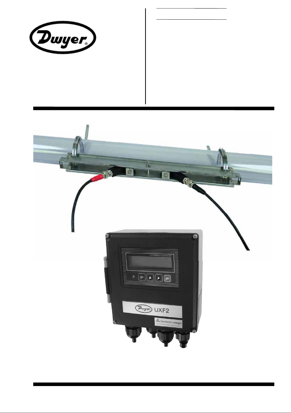
Instruction Manual
ULTRASONIC FLOWMETER
TYPE: UXF2 (Flow transmitter)
SX2 (Detector)
SX3C (Signal cable)
Dwyer Instruments, Inc.
Bulletin F-70
Page 2

Page 3

B
ULLETIN F-7
0
PREFACE
Thank you for purchasing Dwyer Instruments ultrasonic flowmeter Model UXF2.
The instruction manual covers the installation, operation, checkup and maintenance of the flow transmitter (UXF2) and
Detector set (SX3). Review the manual prior to operation.
Before operation, review this instruction manual to ensure correct installation, operation and maintenance
z
of the flowmeter system. Note that incorrect operation may lead to malfunction or personal injury.
The specifications of this flowmeter are subject to change for product improvement without prior notice.
z
Do not attempt to modify the flowmeter without permission. Manufacturer is not responsible for equipment
z
operation or safety compromised as a result of modification without explicit permission. If it is necessary
to modify the flowmeter, contact manufacturer in advance.
z
This instruction manual shall be maintained for reference.
z
After reading the manual, be sure to store it in an accessible location.
z
Manual should be delivered to appropriate operational or technical staff responsible for the flowmeter.
z
If the instruction manual has been lost, request a replacement from the manufacturer.
z
Manufacturer: Dwyer Instruments, Inc.
Type: Described on company nameplate on main frame
Date of manufacture: Desribed on company nameplate on main frame
Product nationality: Japan
Dwyer Instruments, Inc.
Copy of contents of this manual in part or whole is not authorized
z
without written permission.
Contents of this manual are subject to change without prior notice.
z
NOTICE
Issued in June 2007
-i-
Page 4
B
ULLETIN F-70
SAFETY PRECAUTION
Before use, read the following safety precaution to ensure correct operation of the flowmeter.
Ɣ
The following items are important for safe operation and must be fully observed. These items are classified
as "DANGER" and "CAUTION".
Warning & Symbol Meaning
Incorrect handling may lead to a risk of death or severe injury.
Incorrect handling may lead to a risk of medium or light injury, or to a risk of
physical damage.
Ɣ
The items noted under "
Ɣ
All the items are important and must be fully observed.
" may also result in serious trouble depending on circumst ances.
Caution on Installation and Piping
z
This product is not an explosion-proof structure. Do not use it in a place
with explosive gases, otherwise, this may result in serious accident such as
explosion, fire, etc.
z
The unit should be installed in a place conforming with the installation
requirements noted in this instruction manual. Installation in an improper
location may lead to a risk of electric shocks, fire, malfunction, etc.
z
The unit should be installed as noted in the manual. Improper installation
will cause failure, trouble or malfunction of the unit.
z
During installation, make sure that the inside of the unit is free from cable
chips and other foreign objects to prevent fire, trouble, malfunction, etc.
z
The items under "Caution on Installation" noted in the manual must be fully
observed; careless installation may result in trouble or malfunction of the
unit.
Caution on Wiring
z
When performing wiring termination to prevent output trouble caused by
moisture, dew condensation or water leak, follow “Section 3.3 Flow
transmitter wiring” described in this manual
z
Before performing the wiring work, be sure to turn OFF the main power to
prevent electric shocks.
z
Do not perform wiring work outdoors on rainy days to prevent insulation
deterioration and dew condensation; otherwise, it can result in trouble,
malfunction, etc.
z
Be sure to connect a power source of correct rating. Connection of a
power source of incorrect rating may lead to a risk of fire and injury.
z
The unit must be grounded as specified to prevent electric shocks or
malfunction.
z
The analog output signal cable should be wired as far away as possible
from high-voltage lines to prevent electrical interference as it will cause
malfunction of the unit.
z
To prevent malfunction of the unit, the analog output signal cable and
power cable should be wired through separate conduits.
- ii -
Page 5

B
ULLETIN F-7
0
Caution on Maintenance/Inspection
z
The unit should be inspected daily to verify proper measurement
results.
z
When measuring the insulation resistance between the power/output
terminal and the case, follow “Section 5.2.3 How to measure the
insulation resistance” described in this manual.
z
If the fuse is blown, detect and eliminate the cause, and then replace the
fuse with a spare. If there are no spares, replace the fuse with equivalent
specified in this manual (may be procured locally). Use of a
fuse other than specified or its short-circuit may cause an electric shock or
fire. The fuse should be replaced according to “Section 5.3 How to
replace the fuse” described in this manual.
- iii -
Page 6
B
ULLETIN F-70
CAUTION ON INSTALLATION LOCATION
(1) Sufficient space is required for daily inspection, proper wiring, etc.
(2) A location not exposed to direct sunshine nor weathering.
(3) Isolation from excess vibration, dust and moisture.
(4) A location not subjected to radiated heat from a heating furnace etc.
(5) A location not subjected to corrosive atmosphere
(6) A location not to be flooded
(7) A place remote from electrical devices (motor, transformer, etc.) which generate electromagnetic
induction noise, electrostatic noise, etc.
(8) A location not subject to excessive fluid pulsation (near pump discharge side)
(9) A location that provides sufficient flow conditioning with the length of the straight pipe.
(10)A place where ambient temperature and humidity are • 20 to +50qC and 90% RH or less for flow
transmitter, and • 20 to +60
C and 90% RH or less for detector set.
q
- iv -
Page 7

B
ULLETIN F-7
0
CONTENTS
PREFACE ·········································································································································· i
SAFETY PRECAUTION ················································································································· ii
CAUTION ON INSTALLATION LOCATION··············································································· iv
CONTENTS·······································································································································v
1. OUTLINE OF PRODUCT·············································································································1
1.1. Outline·····································································································································1
1.1.1. Measuring principle·················································································································1
1.2. Checking the received products······························································································2
1.3. Checking the type and specifications······················································································3
1.4. Names and functions of each part···························································································6
1.4.1. Flow transmitter ······················································································································6
1.4.2. Detector ··································································································································7
2. SELECTION OF INSTALLATION PLACE·················································································8
2.1. Flow transmitter······················································································································8
2.2. Detector···································································································································9
2.2.1. Length of straight pipe·············································································································9
2.2.2. Mounting position ················································································································· 11
3. INSTALLATION AND PROCEDURE PRIOR TO OPERATION·············································12
3.1. Outline of installation procedure···························································································12
3.2. Installation of flow transmitter······························································································13
3.2.1. Wall mounting ·······················································································································13
3.2.2. 2B pipe stand mounting ·········································································································13
3.3. Flow transmitter wiring·········································································································14
3.3.1. Precautions in wiring ·············································································································14
3.3.2. Applied w iring·······················································································································14
3.3.3. Tre atm ent of wiring ports·······································································································14
3.3.4. Wir ing to each terminal·········································································································· 15
3.4. Setting the piping parameters and calculating the sensor unit spacing·································16
3.5. Installation of detector ······ ··································································································18
3.5.1. Outline of detector installation procedure···············································································18
3.5.2. How to treat the mounting surface ·························································································18
3.5.3. How to mount the frame ········································································································18
3.5.4. How to mount the sensor unit ································································································21
3.6. Installation of detector ······································································································23
3.6.1. Outline of detector installation procedure···············································································23
3.6.2. Selection of mounting method ·······························································································23
3.6.3. Processing of detect or mounting surface················································································23
3.6.4. Determination of mounting position
(with Z method for small type)
·············································24
-v-
Page 8

B
ULLETIN F-70
3.6.5. Cable end treatment ···············································································································25
3.6.6. Connection of cable to small detector ····················································································26
3.6.7. Mounting of small detector on pipe························································································29
3.6.7.1. Mounting of detector (SX3-C0) <V method>····························································29
3.6.7.2. Mounting of detector (SX3-D0) <Z method>···························································· 31
3.7. Confirmation of received signal··························································································· 33
3.8. How to remove the sensor unit (SX3-A0/B0)····································································· 34
3.9. Setting the range and total pulse output ··············································································· 35
3.10. How to calibrate zero ········································································································· 38
4. PARAMETERS···························································································································39
4.1. Description on display/setting section·················································································· 39
4.2. Configuration of keys··········································································································· 40
4.3. Initial values of parameters ·································································································· 43
4.4. Parameter protection ············································································································ 45
4.4.1. Parameter protection ON/OFF·······························································································45
4.5. Output setup mode ··············································································································· 46
4.5.1. Adjusting zero point···············································································································46
4.5.2. Setting the da mping ···············································································································47
4.5.3. Setting the low flow rate cutting····························································································48
4.5.4. Setting the LCD indication·····································································································49
4.5.5. Setting the flow rate a n d flow velocity range·········································································50
4.5.5.1. Setting the flow rate range (single range FLOW SPAN-1)········································· 50
4.5.5.2. Setting forward automatic 2 ranges··········································································· 51
4.5.5.3. Setting forward/reverse automatic 2 ranges······························································· 53
4.5.5.4. How to set analog output at error (BURNOUT) ························································55
4.5.6. Setting the total······················································································································ 57
4.5.6.1. Setting the total pulse (pulse value, pulse width)·······················································57
4.5.6.2. Setting the preset value·····························································································60
4.5.6.3. TOTAL mode (total reset, start, stop) ········································································61
4.5.6.4. Determining how to handle the total at error (BURNOUT) ·······································62
4.5.7. Setting the DO o u tput ············································································································ 64
4.5.7.1. Invalidati ng the DO output························································································65
4.5.7.2. How to validate the total pulse output ·······································································66
4.5.7.3. How to validate outputting the FLOW SPAN-2·························································67
4.5.7.4. How to validate the alarm output···············································································68
4.5.7.5. How to validate the flow switch················································································69
4.5.7.6. How to validate the total switch················································································ 71
4.5.8. How to compensate the measurement value···········································································73
4.6. Measure setup mode·············································································································74
4.6.1. How to set the unit system·····································································································74
4.6.2. How to set the flow rate unit·································································································· 75
4.6.3. How to set the total unit········································································································· 76
4.6.4. How to set the piping parameters···························································································77
4.7. Maintenance mode ··············································································································· 79
4.7.1. How to calibrate the analog output·························································································79
4.7.2. How to set the constant current outp ut···················································································80
4.7.3. How to check the action of total pulses··················································································81
4.7.4. How to check the s tatus output·······························································································82
4.7.5. How to validate the test mode (simulated flow ra te output)····················································83
- vi -
Page 9

B
ULLETIN F-7
0
4.7.6. How to validate a serial transmission (RS-232C/RS-485)······················································85
4.7.7. How to validate the synchronization······················································································87
4.7.8. How to select the language ····································································································88
4.7.9. How to set the ID No.············································································································89
4.7.10. How to confirm the software version···················································································90
5. MAINTENANCE AND CHECKUP···························································································91
5.1. Routine checkup····················································································································91
5.2. Periodic checkup···················································································································91
5.2.1. Checking the zero point ·········································································································91
5.2.2. Reapplying silicon-free grease ······························································································· 91
5.2.3. How to measure the insulation resistance···············································································92
5.3. How to replace the fuse·········································································································93
5.4. How to replace the relay ·······································································································94
5.5. How to replace the LCD ·······································································································95
5.6. Selecting the detector············································································································96
5.7. Troubleshooting····················································································································97
5.7.1. If indication is abnormal········································································································97
5.7.1.1. Checking the LCD/LED····························································································97
5.7.1.2. Checking the LED lit in red······················································································98
5.7.1.3. Displaying the data in maintenance mode ·································································99
5.7.2. If keying is abnormal···········································································································100
5.7.3. If measureme nt value is abnormal························································································100
5.7.4. If analog output is abnormal·································································································103
5.7.5. How to check the received waveform··················································································104
5.7.5.1. How to connect the oscilloscope············································································· 104
5.7.5.2. Checking the received waveform ············································································ 105
5.7.6. Remedying a hardware fault ································································································ 106
6. APPENDICES ···························································································································107
6.1. External communication specifications ··············································································107
6.1.1. Communication specifications·····························································································107
6.1.2. Message configuration········································································································· 108
6.1.2.1. Reception················································································································ 108
6.1.2.2. Acknowledge ·········································································································· 108
6.1.2.3. Error acknowledge··································································································108
6.1.3. Error check·························································································································· 108
6.1.4. Function code table·············································································································· 109
6.1.5. Error code table ··················································································································· 109
6.1.6. Cable connection specifications (RS-232C)········································································· 109
6.2. How to make gauge paper···································································································111
6.3. Piping Data··························································································································112
-vii-
Page 10

Page 11
B
ULLETIN F-7
0
1. OUTLINE OF PRODUCT
1.1. Outline
This flowmeter is a clamp-on type ultrasonic flowmeter for permanent use based on transit time measuring methods. The
UXF2 is ideal for clean liquids containing no air bubbles such as pure water. The easy-to-use compact and
lightweight design is intended for integration into mechanical devices.
The flowmeter is applicable to small and medium size pipes of diameter range from 25mm to 600mm providing superior cost
performance.
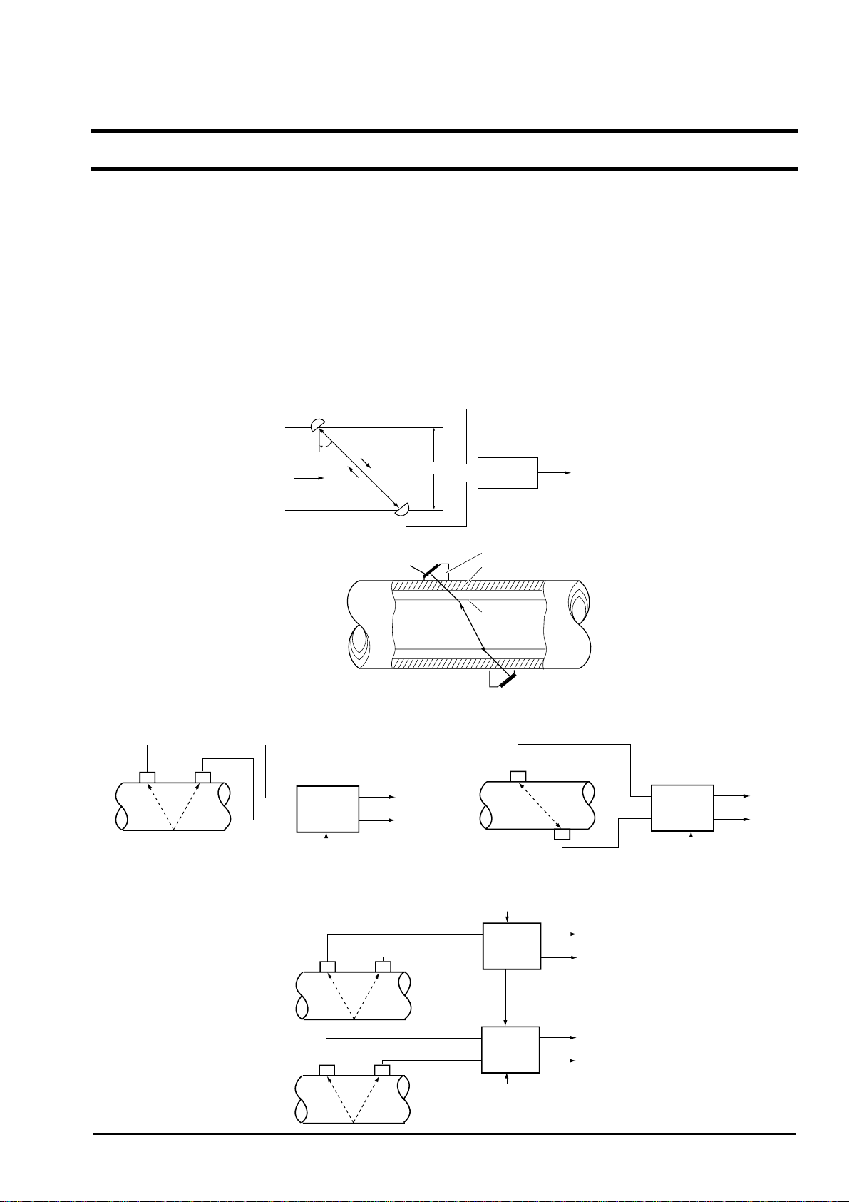
1.1.1. Measuring principle
Measuring principle
Ultrasonic pulses are propagated diagonally from the upstream and downstream sides, and the time difference caused by the
flow is detected to provide the flow rate measurement.
Detector
Upstream sensor
Mounting the detector
Configuration diagram
(1) Single-path system (V method)
Signal cable
Detector
θ
t
2
t
Flow velocity
Downstream sensor
Ultrasonic transducer Pipe
Flow
transmitter
Power supply
1
4 to 20mA
DC
Contact
D
Flow
transmitter
Plastic wedge
Lining
Output signal
(2) Single-path system (Z method)
Signal cable
Detector
Flow
transmitter
4 to 20mA
DC
Contact
Power supply
(3) When synchronizing
Detector
Detector
Signal cable
Signal cable
Power supply
Flow
transmitter
(master)
Synchronizing
signal wiring
Flow
transmitter
Power supply
(slave)
4 to 20mA
DC
Contact
4 to 20mA
DC
Contact
-1-
Page 12
B
ULLETIN F-70
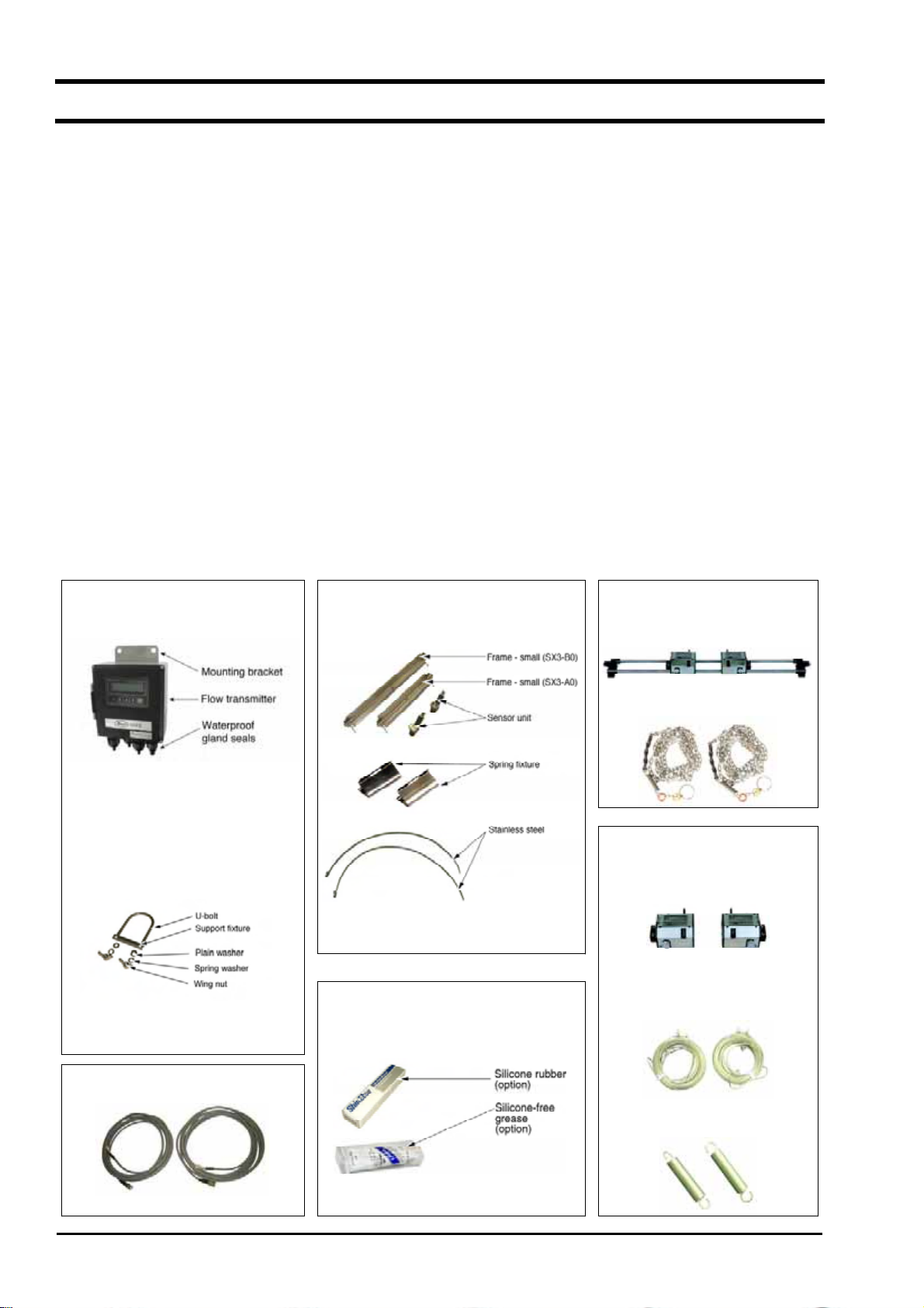
1.2. Checking the received products
Flow transmitter (UXF2)
x
Flow transmitter unit······································································1 set
W aterproof gland ············································································1 set (mounted on main unit)
W all mounting fixture ····································································1 set (mounted on main unit)
Pipe mounting fixture (option) ·······················································1 set
(U bolt, support fixture, 2 wing nuts, 2 spring washers, 2 plain washers)
Detector (SX3-A0/B0)
x
Frame ···························································································1 pc
Sensor unit ······················································································1 set (2 pcs)
Stainless steel belt ···········································································1 set (SX3-A0: 2 pcs. SX3-B0: 4 pcs.)
Spring fixture···················································································2 pcs
Silicone rubber or silicone-free compound (option) ······················1 pc
Detector (SX3-C0)
x
Small detector ················································································1 set (2 pcs)
Chain······························································································1 set (2 pcs)
Detector (SX3-D0)
x
Small detector ·················································································1 set
Wire rope ······················································································1 set (2 pcs)
Mounting spring··············································································1 set (2 pcs)
Signal cable (for SX3-A0/B0) (SX3C: length designated) ·········· 1 set (2 pcs)
x
Signal cable (for SX3-C0/D0) (SX3C: length designated) ·········· 1 set (2 pcs)
x
Instruction manual ··········································································1 copy
x
Belt tightening tool (option) ························································· As ordered
x
Flow transmitter (UXF2)
Piping mounting fixture Detector (SX3-D0)
Detector (SX3-A0, SX3-B0) Detector (SX3-C0)
Small size detector
Chain
Small size detector
Option
Wire rope
Signal cable (SX3C)
Mounting spring
- 2 -
Page 13
B
ULLETIN F-7
0
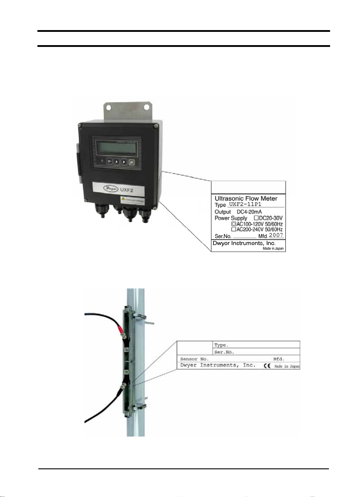
1.3. Checking the type and specifications
The type and specifications of product are indicated on the specifications plate mounted on the flow transmitter and
detector frame. Make sure the models are as ordered referring to the type diagrams given below.
<Flow transmitter (UXF2)>
<Detector (SX3-A0/B0)>
-3-
Page 14

B
ULLETIN F-70
<Detector (SX3-C0/D0)>
- 4 -
Page 15

1021 345678 1191213
B
0
3YYSVLF-
Enclosure (4th digit code)
S
1
4
2
1
0
Y
Y
T
E
F
PAGE BLANK
(Reserved for future use)
Outdoor immersion-proof case
Power supply (5th digit code)
100 to 240V AC±10%, 50/60Hz
20 to 30V DC
Transistor output (6th digit code)
2 Points
Analog output (7th digit code)
1 system
Synchronism (9th digit code)
None
Conduit connections (10th digit code)
G1/2(Female screw)
with water-proof connection
Option (11th digit code)
None
Tag name plate
Use for explosion-proof sensors
Use for explosion-proof sensors with Tag
name plate
ULLETIN F-7
Description
-5-
Page 16
B
ULLETIN F-70
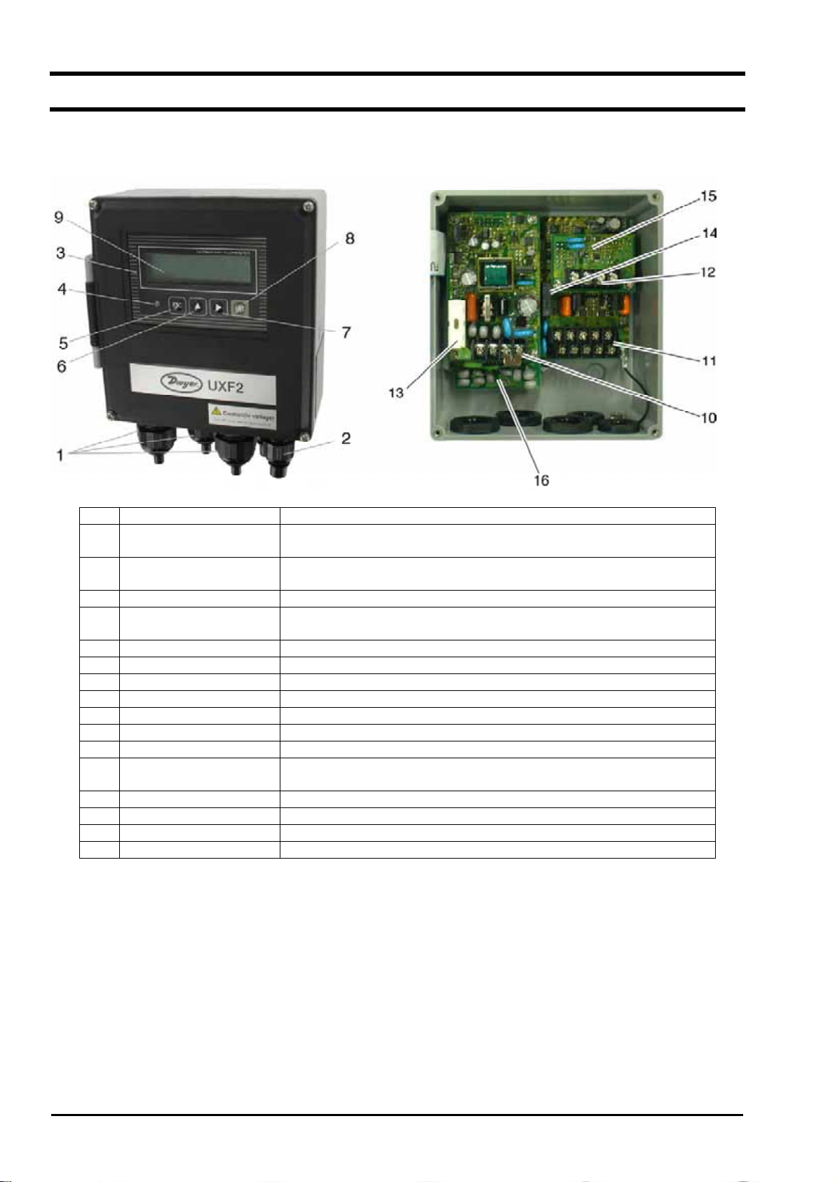
1.4. Names and functions of each part
1.4.1. Flow transmitter (UXF2)
No. Name Description
1 Wiring connection port,
large
2 Wiring connection port,
small
3 Indication and setting unit Indicates and sets the flow rate, etc.
4 Received wave diagnostic
indication
5 Escape key Return to the next-higher layer or cancels the set status.
6 UP key Selects items, numeric values and symbols.
7 Shift key Moves the cursor and selects decimal place.
8 Entry key Enters a selection or registers a setting.
9 LCD indication Indicates the flow rate or setting.
10 Power terminals Power cables are connected.
11 Input/output terminals Signal cable, analog output and DO output cables are connected.
12 Communication board
terminals
13 Fuse holder Houses a fuse.
14 Relay For DO2 output
15 Communication board Mounted if communication synchronization is optionally designated.
16 Arrester board Board for output mounted if arrester is optionally designated.
For power cable, output cable
Wiring connection port for signal cable only
Indicates whether received wave is normal (green) or abnormal (red).
Communication cable is connected (communication board is optional).
- 6 -
Page 17
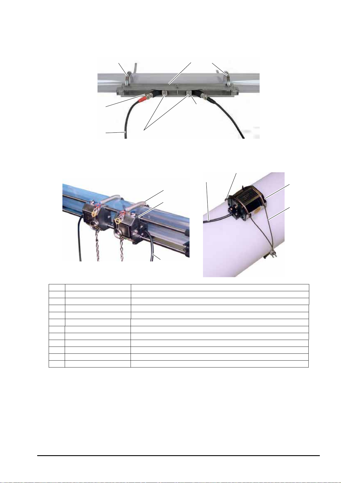
1.4.2. Detector (SX3 Series)
S
B
0
SX3-A0/B0
ULLETIN F-7
3
13
X3-C0/D0
6
7
2
9
8
7
5
11
7
8
10
No. Name Description
1 Frame for small size Fastens the sensor unit on pipe.
2 Sensor unit Sends and receives an ultrasonic wave.
3 Stainless steel belt Fastens the frame on pipe.
4 Spring fixture Removes the play of stainless steel belt.
5 Scale For reading the sensor mounting spacing
6 Fastening hole For positioning and fastening the sensor units
7 Signal cable Transmits send/receive signals.
8 Small size detector Sends and receives an ultrasonic wave.
9 Chain Fastens the detector on pipe.
10 Wire rope Fastens the detector on pipe.
11 Mounting spring Removes the play of wire rope.
-7-
Page 18
B
ULLETIN F-70
2. SELECTION OF INSTALLATION PLACE
Select an installation place taking into account the following factors from the viewpoint of ease of maintenance and
checkup, instrument life, and reliability.
(1) A place where ambient temperature and humidity are –20 to +50qC and 90% RH or less for flow
transmitter (UXF2), and –20 to +60qC and 90% RH or less for detector SX3.
(2) A place not exposed to direct sunshine nor effects of weather.
(3) Sufficient space for daily inspection, wiring, etc.
(4) A location not subject to radiated heat from a heating furnace, etc.
(5) A location not subjected to corrosive atmosphere.
(6) A location not subject to flooding.
(7) A location free from excessive vibration, dust, dirt and moisture.
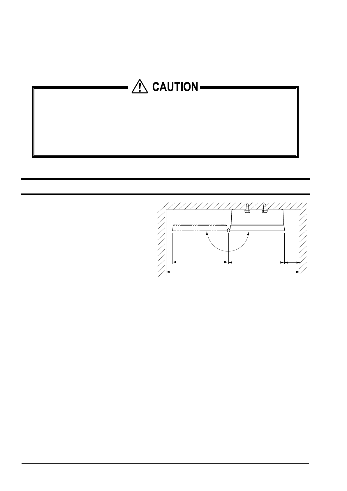
2.1. Flow transmitter
Secure at least 100 mm of space between the flow
transmitter and nearby wall. Also secure a space for
opening the front cover for maintenance.
Secure a cable wiring space under the enclosure.
N
E
P
O
133 100133
370 min.
Top view of mounting
min.
- 8 -
Page 19
B
ULLETIN F-7
0
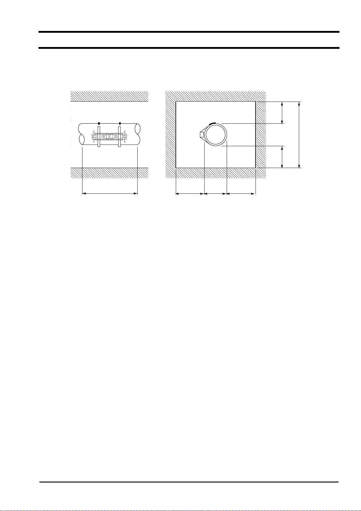
2.2. Detector
The measuring accuracy is considerably affected by the detector mounting place, i.e., status of piping for measuring a flow
rate. Select a place which meets the condition in section 2.2.1. (Length of straight pipe). Also, sufficiently secure a
space for installation and maintenance in accordance with the following diagram.
2000min.
Note
200min. 200min.
D + 1200 min. 600min. D 600min.
D: Pipe diameter
Necessary space for detector mounting place
2.2.1. Length of straight pipe
The length of upstream and downstream straight pipe of the ultrasonic detector should be long enough to ensure accurate
measurements.
-9-
Page 20
B
ULLETIN F-70
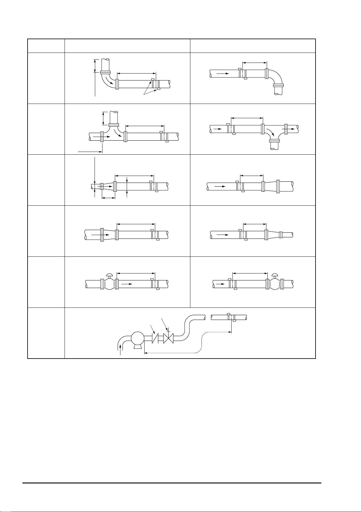
(D: Nominal diameter of pipe)
Name Straight length of upstream piping Straight length of downstream piping
L≥5D
L≥10D
90° bend
Tee
Diffuser
Reducer
10D min.
0.5D min.
10D min.
10D min.
1.5D min.
Detector
L≥50D
L≥30D
D
L≥10D
L≥10D
L≥5D
L≥5D
Valve
Pump
Note: Quoted from JEMIS-032
L≥30D
Flow controlled upstream
Check valve
Stop valve
P
L≥10D
Flow controlled downstream
L≥50D
- 10 -
Page 21
2.2.2. Mounting position
B
0
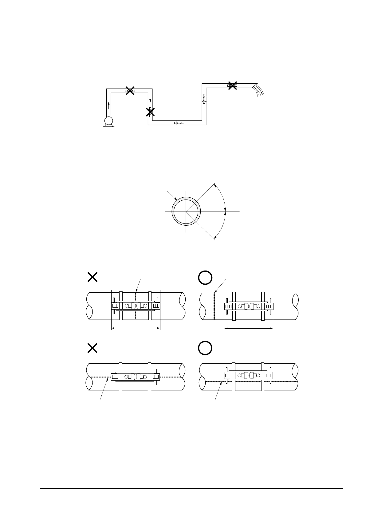
The detector can be installed vertically, horizontally or in any position provided the following:
(1) The piping must completely be filled with fluid when it flows.
ULLETIN F-7
Air tends to accumulate.
May not
completely be
filled with liquid.
Pump
May not completely be filled with liquid.
Good
Good
(2) In case of horizontal piping, mount the detector within r45q from the horizontal plane. Otherwise, the measurement
could be impossible if bubbles stay in the upper part of piping or if deposits are accumulated in the lower part of
piping. In case of vertical piping, the detector may be mounted at any position on its periphery provided that the
flow is upward.
Pipe
45°
Horizontal
45°
(3) Do not mount the detector on a distorted part, flange or welding.
Weldment
Welding is included.
Welding is partly involved.
Avoid Welding.
Weldment
Off the Welding.
-11-
Page 22

B
ULLETIN F-70
3. INSTALLATION AND PROCEDURES PRIOR
TO OPERATION
3.1. Outline of installation procedure
(1) Select the flow transmitter and detector installation places.
(2) Install and wire the flow transmitter.
(3) Turn on powe r.
(4) Set the piping parameters, and calculate the sensor unit spacing (if already programmed, check the sensor unit
spacing).
(5) Mount the frame on the piping to measure on.
(6) Mount the sensor unit.
(7) Set the measurement range.
(8) Adjust zero point.
(9) Start a measurement.
- 12 -
Page 23
3.2. Installation of flow transmitter
3.2. Installation of flow transmitter
The flow transmitter may be mounted on a wall or 2B pipe stand (option).
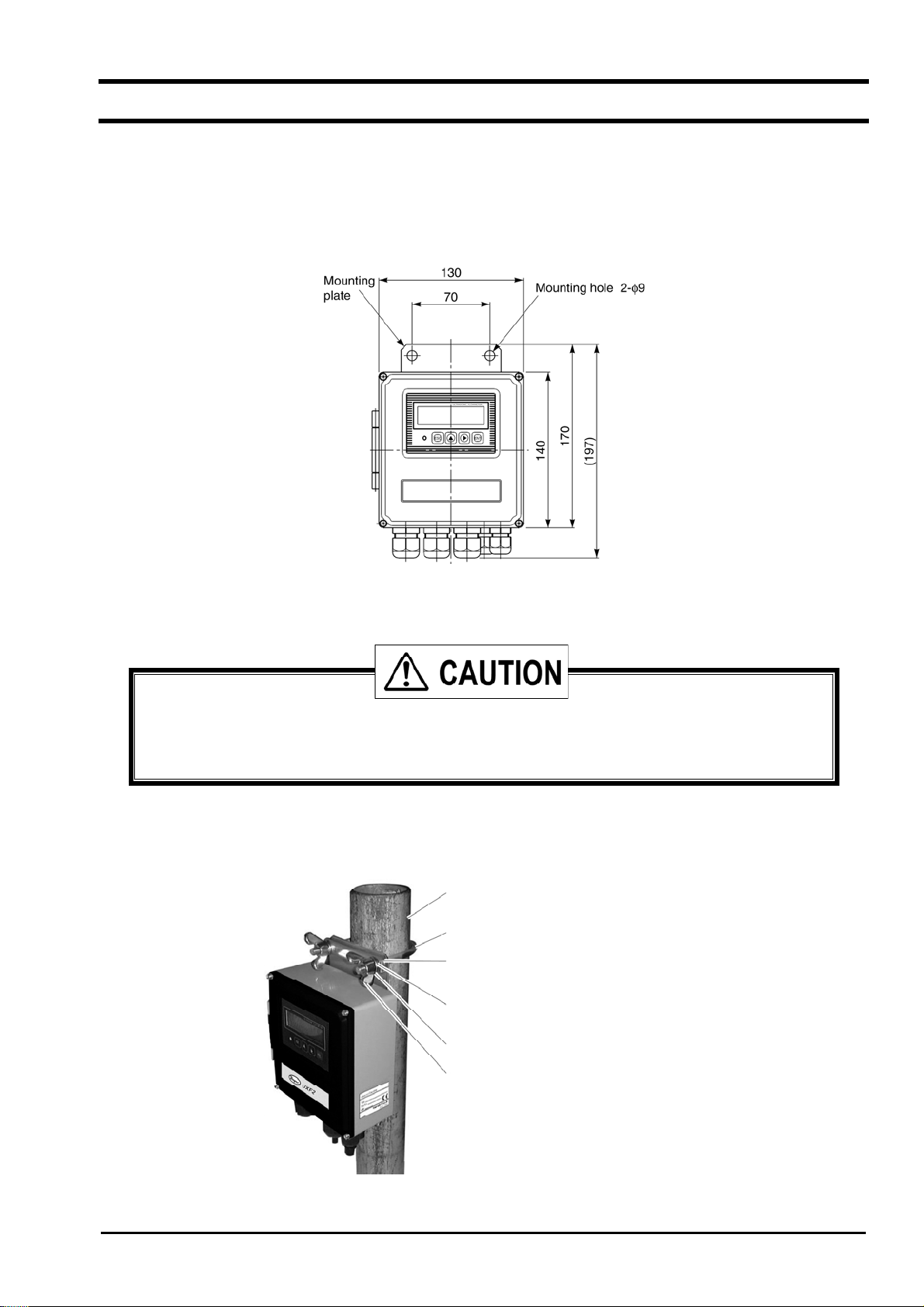
3.2.1. Wall mounting
For wall mounting, use two M8 bolts.
According to the mounting hole dimensions shown below, drill holes on the wall, and tighten M8 bolts.
3.2.2. 2B pipe stand mounting
When mounting on 2B pipe, be sure to use the complete set of fixtures (U bolt, support fixture, plain washer,
spring washer, wing nut) that are provided. Tighten the wing nut by hand. Assemble pipe mounting
components as shown in the figure below and do not overtighten. Overtightening may warp or damage the
plastic enclosure.
Mount the instrument on 2B pipe stand as illustrated below.
2B Pipe stand
U - bolt
Fixture assembly
Plain washer
Spring washer
Wing nut
-13-
Page 24
B
ULLETIN F-70
3.3. Flow transmitter wiring
3.3.1. Precautions in wiring
(1) Use a special coaxial cable (SX3C) as a signal cable between the detector (SX3) and flow
transmitter (UXF2). Continuous lengths are required. Signal cables may not be spliced or joined.
(2) Be sure to pass the signal cables through a metal conduit between the detector and flow transmitter.
Upstream and downstream signal cables may be put in the same conduit but, to avoid an interference, do
not put the power cable together.
(3) For output signal, use a shielded cable, where possible.
(4) To avoid noise interference, do not run cables through conduits carrying heavy duty or high voltage
lines.
(5) If a ground wire is included in the power cable, connect it to ground as it is.
(6) A power switch is not provided on the instrument and must be mounted separately if required.
(7) Cover unused wiring glands and protect from moisture intrusion.
3.3.2. Applied wiring
Use the following cables.
Power cable : 3 or 2 core cabtyre cable.
z
Nominal cross-sectional area 0.75 mm
Finished outer diameter 11 mm.
Output signal cable : 2 or, as required, multiple core cabtyre cable.
z
Finished outer diameter 11 mm.
Detector-flow transmitter cable : Signal cable by type designation (heat-resisting high-frequency coaxial cable having
z
50: of characteristic impedance. In case SX3-A0/B0, provided with oneside waterproof BNC connector).
Finished outer diameter 5 mm.
2
min.
3.3.3. Treatment of wiring ports
The outer case of flow transmitter is waterproof (IP65). However, if installed in a humid place, the wiring ports must be
made airtight to avoid ingress of moisture, condensation, etc. Be sure to use the waterproof glands furnished with the
instrument in order to ensure the waterproof seal. Hermetically seal unused glands with caps provided.
Do not install the instrument where there is a risk of flooding.
- 14 -
Page 25
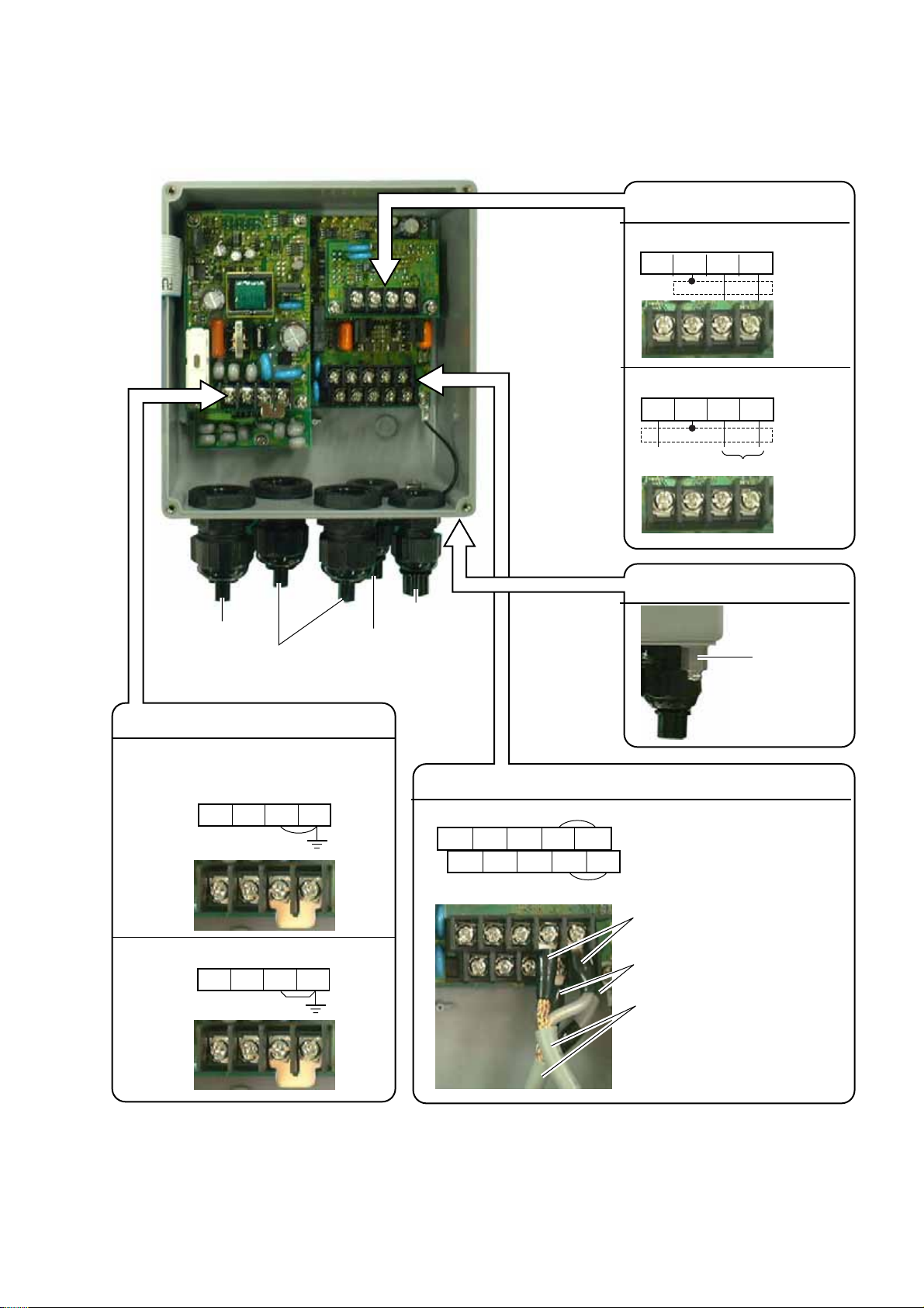
3.3.4. Wiring to each terminal
B
0
Refer to the following diagram for carrying out wiring.
ULLETIN F-7
Communication board terminal block (option)
RS-232C
NC
GND RXD TXD
RS-485 and synchronization
SYNC
SHILD TXDR2 TXDR1
Power cable
Output signal cable
(analog output, DO1, DO2,
communication synchronization)
Downstream
sensor cable
Power board terminal block
AC power source: 100 to 120 or 200 to 240 V AC,
50/60 Hz
LN
GND GND
Upstream
sensor cable
Main board terminal block
Iout(+) DO1(+) DO2(+)
Iout(-) DO1(-) DO2(-)
Upstream sensor
GND HF1
GND HF2
Downstream sensor
Synchronization
RS-485
External ground terminal
Ground terminal
Red (upstream sensor)
DC power source: 20 to 30V DC
+−
GND GND
Black (downstream sensor)
Special signal cable (SX3C)
Iout : Analog output
DO1 : Transistor open collector
DO2 : Relay contact
Notes
1. All screws are M3 on the terminal block. Use crimp-style terminals for M3 and whose outer diameter is 5.8 or
smaller.
2. Be sure to connect to ground the power board terminal block or external ground term in al (class D ground).
3. For output signal, use multiple core cable as required.
-15-
Page 26
B
ULLETIN F-70
3.4. Setting the piping parameters and calculating the
sensor unit spacing
After installation and wiring of the flow transmitter (sensor unit may not be wired), turn on power, input the piping
parameters below, and calculate the sensor unit installation spacing. (If the unit is already programmed, the
following parameters have already been input. Check the installation spacing in this case.)
Item Input
method
Pipe outer diameter Value 10 to 650mm
Pipe material Menu PVC, PVDF, PEEK, PP, CARBON STEEL, STAINLESS STEEL, COPPER,
PIPE S.V (Note 1)
Pipe wall thickness Value 0.1 to 100mm
Lining presence and
material selection
Lining thickness Value 0.1 to 10mm
Fluid type Selection Water, Sea water, FLUID S.V (Note 1)
Kinematic viscosity Value 0.00E–6m2/s to 999.999E–6 m2/s (Note 1)
Detector mounting
method
Detector type Selection SX3 A0, SX3 B0, SX3 C0, SX3 D0
Note 1: In case of material or fluid not included in menus, input its sound velocity and kinematic viscosity of the
fluid. The sound velocity can be entered within the range of 1000 to 3700 m/s for piping or lining
material, or 500 to 2500m/s for fluid. (Refer to section 6.6.)
The operating procedure is as follows (from measurement mode).
Note 2: If the parameter protection is set at "PROTECTION ON", change it to "PROTECTION OFF". If ID NO.
is set at this time, ID NO. must be entered.
Keying
key pressed 3 times.
Menu NO LINING, TA R EPOXY, MORTAR, RUBBER, TEFLON, PYREXGLASS,
LINING S.V (Note 1)
Selection V method, Z method
1st line: [MEASURE SETUP].
Range or menu
LCD indication/comment
ENT
key pressed.
key pressed 3 times.
ENT
key pressed.
ENT
key pressed.
and key pressed.
ENT
pressed to enter.
key pressed.
ENT
key pressed.
key pressed to select.
ENT
key pressed to enter.
key pressed.
ENT
key pressed.
1st line: [SYSTEM UNIT].
1st line: [PIPE PARAMETER].
1st line: [OUTER DIAMETER]. 2nd line: [60.00 mm]. * As selected currently.
Cursor blinks on 2nd line.
Input the outer diameter of a measurement pipe. As necessary, check the piping data
in section 6.6.
: Selects a numeric. : Shifts the place.
Registered after [**COMPLETE**] is indicated about 1 second on 2nd line.
1st line: [PIPE MATERIAL]. 2nd line: [PVC] * As selected currently.
Cursor blinks on 2nd line.
Select the pipe material from menus. If there is no corresponding menu, input the
sound velocity of pipe material on sound velocity input screen
If necessary, refer to piping data in section 6.6.
Registered after [**COMPLETE**] is indicated about 1 second on 2nd line.
1st line: [WALL THICKNESS]. 2nd line: [4.50mm] * As selected currently.
Cursor blinks on 2nd line.
.
- 16 -
Page 27
B
ULLETIN F-7
0
Keying
and key pressed.
ENT
key pressed to enter.
key pressed.
ENT
key pressed.
key pressed to select.
ENT
key pressed to enter.
key pressed.
ENT
key pressed.
and
ENT
key pressed to enter.
key pressed.
LCD indication/comment
Input the wall thickness of the measurement pipe. As necessary, check the piping data
in section 6.6.
: Selects a numeric. : Shifts the place.
Registered after [**COMPLETE**] is indicated about 1 second on 2nd line.
1st line: [LINING MATERIAL]. 2nd line: [NO LINING]. * As selected currently.
If pipe is not lined, press
key to go to selection of next fluid to be measured.
Cursor blinks on 2nd line.
Select the lining material from menus. If there is no corresponding menu, input the
sound velocity of lining material on sound velocity input screen
.
If necessary, see lining data in section 6.6.
Registered after [**COMPLETE**] is indicated about 1 second on 2nd line.
1st line: [LINING THICKNESS]. 2nd line: [2.00 mm]. * As selected currently.
Note: Not indicated if lining material is set at [NO LINING].
Cursor blinks on 2nd line.
Input the lining thickness.
: Selects a numeric.
: Shifts the place.
Registered after [**COMPLETE**] is indicated about 1 second on 2nd line.
key pressed.
ENT
key pressed.
key pressed to select.
ENT
key pressed to enter.
key pressed.
ENT
key pressed.
and
ENT
key pressed to enter.
key pressed.
key pressed twice.
ENT
key pressed.
key pressed.
ENT
key pressed to enter.
1st line: [KIND OF FLUID]. 2nd line: [WATER]. * As selected currently.
Cursor blinks on 2nd line.
Select [WATER] or [SEA WATER]. In case of other fluid, input the sound velocity of
fluid on sound velocity input screen
.
If necessary, see piping data in section 6.6.
Registered after [**COMPLETE**] is indicated about 1 second on 2nd line.
1st line: [KINEMATIC VISCO]. 2nd line: [1.0038E–6m2/s]. * As selected
currently. Kinematic viscosity of water is factory set. If fluid to be measured is
other than water, input the kinematic viscosity referring to piping data in section 6.6.
Cursor blinks on 2nd line.
Input the kinematic viscosity.
: Selects a numeric.
: Shifts the place.
Registered after [**COMPLETE**] is indicated about 1 second on 2nd line.
1st line: [SENSOR TYPE]. 2nd line: [SX3-A0/B0]. * As selected currently.
Cursor blinks on 2nd line.
Select [SX3-A0/B0] or [SX3-C0/D0].
Registered after [**COMPLETE**] is indicated about 1 second on 2nd line.
ESC
key pressed.
ESC
key pressed.
key pressed twice.
1st line: [PIPE PARAMETER]. 2nd line: [S= 16 ( 48mm)] in case SX3-A/B
Note Sensor unit spacing calculated by above settings is indicated for sensor unit
spacing at detector installation.
1st line: [MEASURE SETUP]
Measurement mode is resumed.
-17-
Page 28
B
ULLETIN F-70
3.5. Installation of detector (SX3-A0, SX3-B0)
3.5.1. Outline of detector installation procedure
(1) Treat the surface to mount on the detector.
(2) Mount the frame.
(3) Mount the sensor unit.
3.5.2. How to treat the mounting surface
By thinner, sandpaper, etc., eliminate rust, pitch, convex and concave from the pipe surface to mount on the detector by the
frame length to occupy.
Note: 1. If jute is wound on the pipe, peel off the jute over the entire periphery by frame length (L) + 200 mm
beforehand.
Jute winding
Pipe
L+200mm
Fig. 3-1 L: Frame length (SX3-A0: 228 mm, SX3-B0 348 mm)
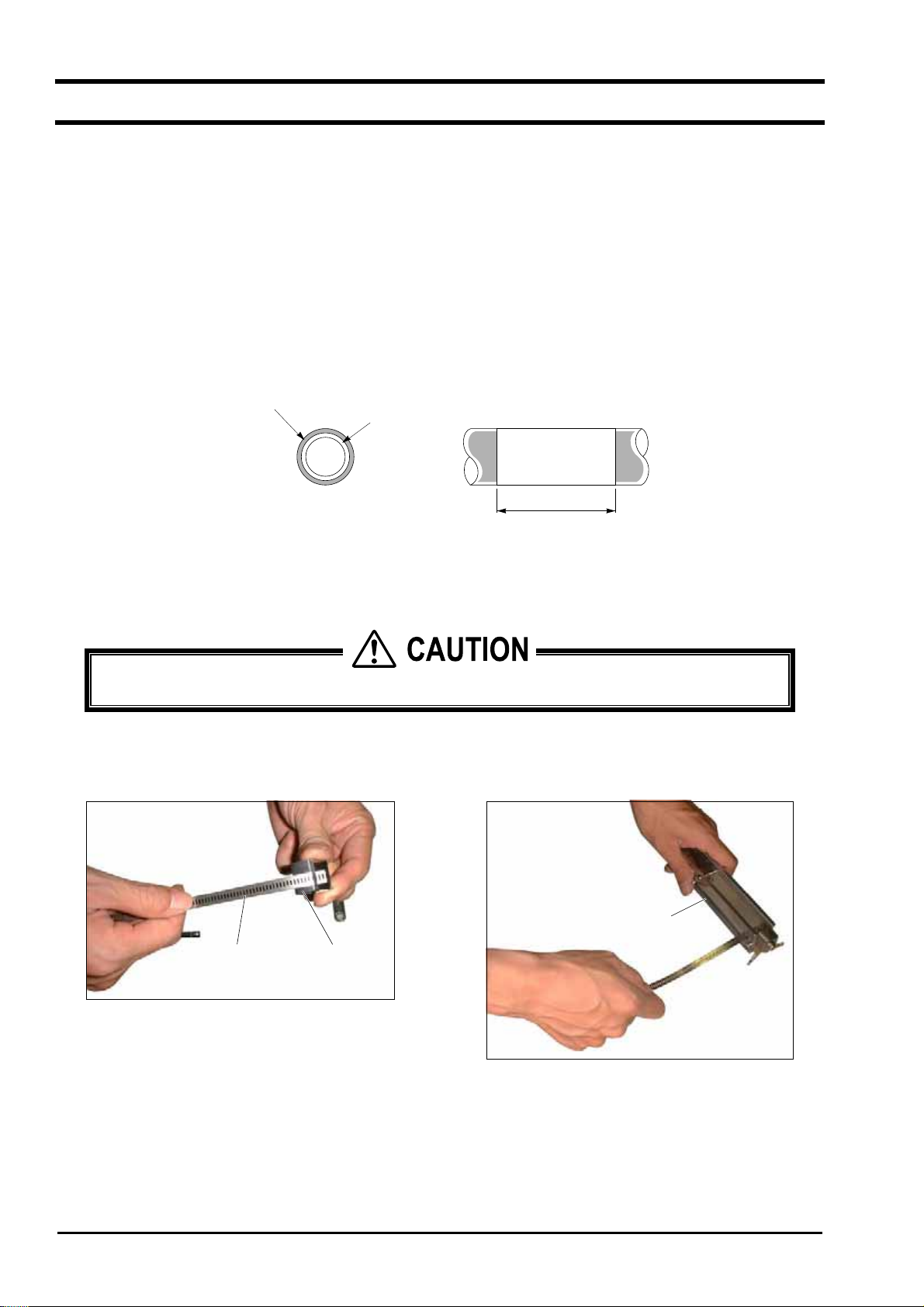
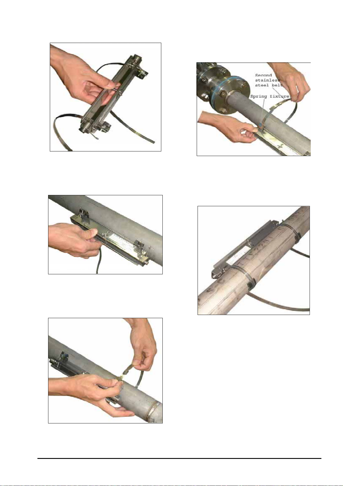
3.5.3. How to mount the frame
Mount the frame carefully not to cut your fingers with stainless steel belt.
z
(1) Pass the spring fixture on the stainless steel belt as
shown in Fig. 3-2.
Stainless steel belt
Spring fixture
(2) Pass the stainless steel belt through 2 belt holes on
the frame as shown in Fig. 3-3.
Frame
Fig. 3-2
Fig. 3-3
- 18 -
Page 29
B
ULLETIN F-7
0
(3) Make sure the obtained status is as shown in Fig. 3-4.
Fig. 3-4
(4) As shown in Fig. 3-5, apply the frame on the pipe
section subjected to a surface treatment.
(6) Adjust the frame so as to be in parallel with the pipe,
put the spring fixture to the side of the frame as
shown in Fig. 3-7, and tighten the stainless steel belt
so that the frame will tightly be fitted.
Fig. 3-7
(7) After tightening both stainless steel belts, slide the
spring fixture to the opposite to the frame as shown in
Fig. 3-8.
Fig. 3-5
(5) Temporarily tighten the first stainless steel belt on the
pipe as shown in Fig. 3-6.
Fig. 3-6
Fig. 3-8
Note: When removing the frame set to the piping and
set it to a different position, use new stainless
steel belts.
- 19 -
Page 30
B
ULLETIN F-70
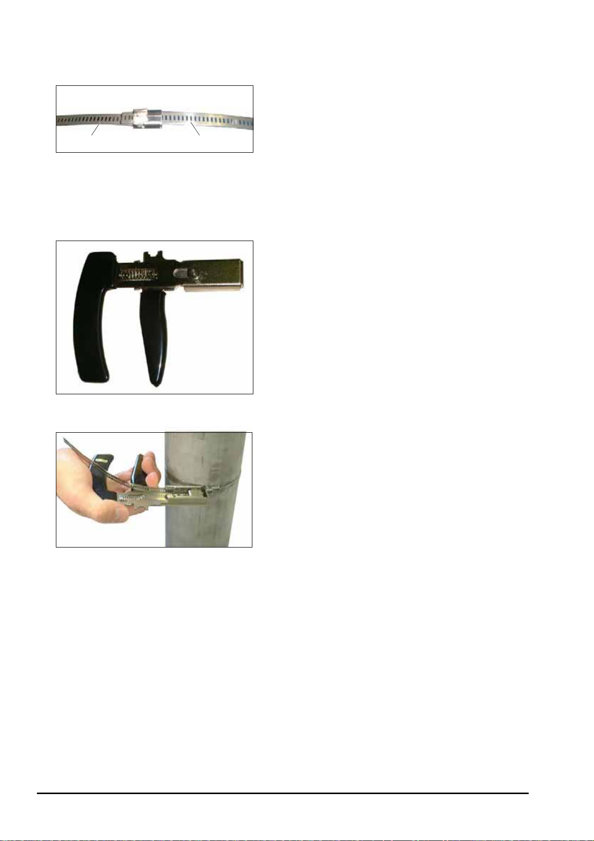
Mounting on pipe whose diameter is 150 mm or larger
As shown in Fig. 3-9, connect 2 stainless steel belts.
First steel belt
Fig. 3-9
Tightening tool
Use of an optional tool (Fig. 3-10) facilitates tightening
the stainless steel belt (Fig. 3-11).
Fig. 3-10
Second steel belt
Fig. 3-11
- 20 -
Page 31
B
ULLETIN F-7
0
3.5.4. How to mount the sensor unit
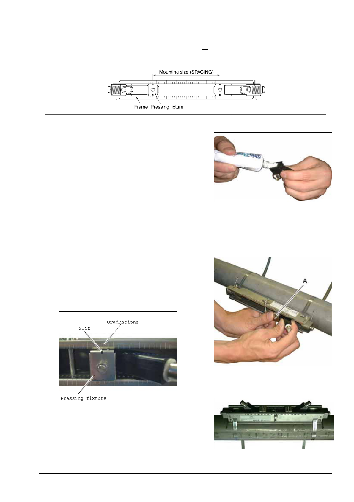
(1) Mount both sensor units spaced at the SPACING value [S= **] (number of graduations on frame) indicated after
setting the piping parameters.
Fig. 3-12
(2) Before mounting the sensor unit into the frame, sufficiently
apply silicone filler (or silicone-free grease
entire transmission surface of the sensor unit, taking care not
to introduce bubbles (Fig. 3-13).
Note) When using silicone-free grease, pay attention to the
fluid temperature range. The fluid temperature range is
shown below.
Silicone rubber: 20 to 100qC
Silicone-free grease: 0 to 60qC
When using silicone-free grease, reapply it on the
transmission surface of the sensor unit approximately
once every 6 months. (Silicone rubber need not be
reapplied.)
(3) Then insert the sensor unit into the frame, align the slit
provided on the pressing fixture of the sensor unit with
graduations located on the frame top surface (see Fig. 3-14),
and press the sensor unit until the fixture claws are engaged
with the frame side square holes. Mount both sensor units
so as to be roughly symmetrical with respect to the frame
(see Fig. 3-15).
Note
) over the
Fig. 3-13
Fig. 3-14
Position of the slit and the graduation
(Magnified view of section A)
Fig. 3-15
- 21 -
Page 32

B
ULLETIN F-70
Mount the sensor units so that their BNC connectors face outward (Fig. 3-16a). If at least one is mounted
opposite, measurement is not possible (Fig. 3-16b, c). The pressing fixture claws must be completely
engaged with square holes provided on sides of the frame. Otherwise, the sensor and pipe will not correctly
get in contact with each other, and measurement error will occur..
Fig. 3-16a
Fig. 3-16b
Fig. 3-16c
(4) Connect the signal lines with BNC connectors of the sensor units. At this time, do not mistake the upstream and
downstream sides for each other. Connect the red BNC connector upstream, and the black BNC connector
downstream (see Fig. 3-17).
Fig. 3-17
- 22 -
Page 33

3.6. Installation of detector (SX3-C0, SX3-D0)
B
0
3.6.1. Outline of detector installation procedure
(1) Selection of detector mounting method
(2) Processing of detector mounting surface
(3) Determination of mounting position (with Z method for small type)
(4) Cable end treatment
(5) Connection of cable to small detector
(6) Mounting of small detector on pipe
3.6.2. Selection of mounting method
There are two ways for mounting the detector, the V method and the Z method (See Fig. 3-18).
ULLETIN F-7
Approx. D
Detector
D
V method
D
Approx. D/2
Detector
Z method
Fig. 3-18
The Z method should be used in the following cases.
Ɣ
Where a mounting space is not available. (As shown in the figure above, the mounting dimension with
the Z method is about half of that with the V method).
Ɣ
When measuring fluid of high turbidity such as sewage.
Ɣ
When the pipe has a mortar lining.
Ɣ
When the pipe is old and has a thick accumulation of scale on its inner wall.
Selection standard
For an inside diameter of more than 300 mm, the Z method is recommended for mounting.
Detector
Small type
detector
SX3-C0, SX3-D0
Z
method
V
method
:Range noted in specifications
13 25 50 100
:Range specified with piping material
(FRP,PVC or other plastic materials)
200 300 600
250
Inside diameter (mm)
3.6.3. Processing of detector mounting surface
Using thinner and/or sandpaper, remove pitch, rust and unevenness over a width of (L) + 200mm on the pipe
circumference where the detector is mounted.
Note) If there is a jute winding on the pipe circumference, remove it and carry out the above processing.
Jute winding
Pipe
L+200mm
-23-
Page 34

B
ULLETIN F-70
3.6.4. Determination of mounting position
(with Z method for small type)
Carry out the following to determine the mounting position.
Gauge paper is necessary for this work. (Refer to 6.5. “How to make gauge paper”.)
(1) Align the edge of gauge paper with a point about 100mm from
one end of the processed section, and wrap the paper around
the pipe so that the line drawn on the paper is parallel with the
pipe shaft. (The paper should be taped to prevent slipping.)
At this time, make sure that the paper edge is even.
(2) Extended the line drawn on the paper and mark a straight line A
on the pipe.
(3) Mark a line along on edge of the paper. Assume the intersection of
0
the line and the straight line A is A
.
100mm
Edge should be even.
Straight line A
A
0
V method
Example) L = 200mm
A
2
200mm
A
0
(4) Remove the gauge paper and measure
the mounting dimension from A
.
0
Then , draw a line which crosses the
straight line A (determine the position
).
A
2
A0 and A2 are the mounting position.
Z method
A
0
Straight line B
0
1
A
B
1
B
B0, B
1
A
0
,
A
(4) Measure the circumference of the pipe from the
point A
between the point B
, and mark a line (straight line B)
0
and B1 obtained at 1/2 of
0
the circumference.
Example) L = 100mm
100mm
B2B
0
A
0
B
B
0
2
1
- 24 -
(5) Put a mark at point B
0
and remove the gauge
paper.
Measure the mounting dimension from B
mark a line crossing the straight line B (determine
the position B
).
2
In this way, the mounting position is determined.
A0 and B2 are the mounting position.
and
0
Page 35

B
ULLETIN F-7
0
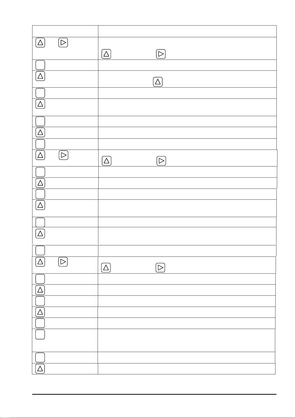
3.6.5. Cable end treatment
The end of coaxial cable is treated at the factory prior to delivery. If the cable needs to be cut
before use, the conductor and the shielding wires should be treated using clamp terminals.
Shielding wire (black, G)Conductor (white, +)
Clamp terminal
Note) When cutting the coaxial cable, make sure that the upstream side and the downstream side are the
same
length.
-25-
Page 36

B
ULLETIN F-70
3.6.6. Connection of cable to small detector
(1) Loosen the retaining knobs on the detector using a
screwdriver, then remove the cover from the
detector.
(2) Mount the sensors so that the upstream and
downstream sensors can be distinguished from
each other. Remove the cable clamp.
Note) In case of removing the cable clamp, be
careful not to lose the nut.
Fig. 3-19
Fig. 3-20
- 26 -
Page 37

B
ULLETIN F-7
0
(3) Insert the coaxial cable through the cable lead-in port
and loosen the terminal screws (G, +).
Note) At this time, temporarily remove the resistor.
(5) Secure the coaxial cable with the cable clamp. Note:
resistor not shown.
Fig. 3-23
Fig. 3-21
(4) Connect the cable to the teminal (black to G terminal,
red to + terminal). Then tighten the cable together
along with with the resistor.
(6) Remove any foreign matter from the terminals, and
seal the terminal block with silicone filler. Resistor
is not shown.
• Cut off the tip of the silicone filler tube.
Apply silicone to the terminal block while pressing
the head of the tube against the bottom of terminals.
At this time, care should be taken to prevent entry
of air bubbles.
Fig. 3-22
Fig. 3-24
- 27-
Page 38

B
ULLETIN F-70
(7) Reinstall the cover onto the detector.
Fig. 3-25
- 28 -
Page 39

B
ULLETIN F-7
0
3.6.7. Mounting of small detector on pipe
The small type detector is mounted on pipe with a diameter of ø50 to 300 (V method) or ø300 to 600 (Z method) for
measurements.
3.6.7.1. Mounting of detector (SX3-C0) <V method>
Mount the detector using the following procedure.
For mounting, have a ruler, scale, or caliper handy for measurement.
(1) Loosen the retaining knob A (4 places), slide the
detectors to match the mounting dimension, place a
scale on the mounting dimension reference surface C
and adjust the separation distance (dimension). Then
tighten the retaining knobs “A”.
(2) Spread silicone filler over the whole transmitting side
of the detector. Ensure enough silicone is applied
smoothly without bubbles and thoroughly to prevent
air gaps.
Clean the surface of the pipe as required and mount
the detector.
Fig. 3-26
Fig. 3-27
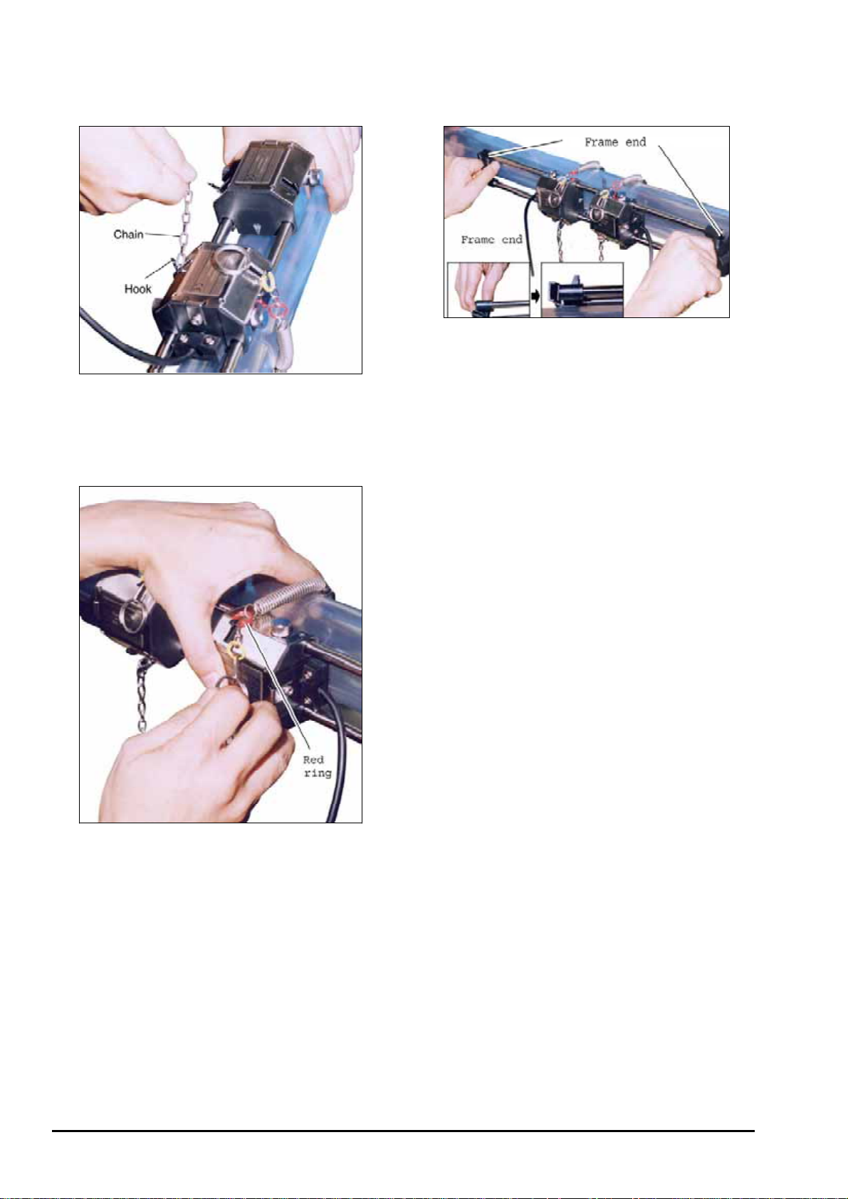
(3) Raise the end of the pipe fitted with the detector, and
attach the yellow ring (on the chain) to the hook.
Fig. 3-28
-29-
Page 40
B
ULLETIN F-70
(4) Attach the other chain end to the other hook of
detector, and secure it loosely in place.
Fig. 3-29
(5) Pull the red ring and attach it to the hook.
Use the same procedure for the other sensor.
(6) Turn over the frame end so that the sensor makes
flush contact with the pipe.
Fig. 3-31
(7) Press the sensor firmly and uniformly against the pipe.
Ensure that the sensor makes a flush contact with the
pipe.
Fig. 3-30
- 30 -
Page 41

3.6.7.2. Mounting of detector (SX3-D0) <Z method>
B
0
Mount the detector using the following procedure:
ULLETIN F-7
(1) Provide wire rope for the upstream and the
downstream detectors. Make sure that the length of
the wire rope is longer than the circumference of the
pipe.
Fig. 3-32
(2) Lay the wire rope around the pipe at the position of
the upstream detector. Then hook the mounting
spring onto the wire rope ends.
(4) Clean the surface of the pipe, then mount the detector.
Fig. 3-35
(5) Press the detector against the pipe. Align the center of
the detector using the intersection of the marking
line and the mounting dimension as a guide.
Fig. 3-33
(3) Spread silicone filler over the whole transmitting side
of the detector smoothly without bubbles. Ensure
there are no air gaps or bubbles.
Fig. 3-36
(6) Make sure that the center mark on the detector is
aligned with the marking line. Then, connect the
coaxial cable to the transmitter.
Note) Do not pull the coaxial cable. If it is pulled,
the detector is shifted which results in
incorrect measurements due to poor contact.
Fig. 3-34
Fig. 3-37
-31-
Page 42

B
ULLETIN F-70
(7) After mounting the upstream sensor, mount the
downstream sensor in the same way.
!
Cable side
Upstream
sensor
Transmitting mark side
Downstream
sensor
Cable sideTransmitting mark side
- 32 -
Page 43

B
ULLETIN F-7
0
3.7. Confirmation of received signal
After connecting the signal line, make sure the red LED on the flow transmitter has turned green. It takes about
10 to 20 seconds until the color changes to green.
The green color indicates the received signal is normal. The red color indicates the received signal is abnormal. If the
LED remains red and does not turn green, examine the
engagement, etc.) and
parameter settings, and check whether the piping is filled with fluid
sensor installation status
(sensor spacing, sensor orientation, claw
.
Fig. 3-38
-33-
Page 44

B
ULLETIN F-70
3.8. How to remove the sensor unit (SX3-A0, SX3-B0)
If the sensor unit has to be detached from the frame such as for changing the spacing between the sensor units, proceed as
follows:
(1) Loosen the wing nut located at the middle of the
frame with 3 to 4 turns (Fig. 3-39).
Note 1: Do not loosen the wing nut completely.
Fig. 3-39
(2) By hand, hold the frame close to the pressing fixture
for a sensor unit to release.
Press the plastic section which extends from the
frame of the sensor unit just enough to open the
frame a little (about 1 mm). At this time, the claws
of the sensor unit fixture are disengaged from the
frame (Fig. 3-40).
(3) Disengage the opposite claws of the sensor unit
pressing fixture from the frame (Fig. 3-41).
Fig. 3-41
(4) Ensure the claws are disengaged from both sides, and
remove the sensor unit from the frame (Fig. 3-42).
Note 2: Do not open the frame excessively. Otherwise,
it may bend, so reinstalling the sensor may be
difficult or the frame may become deformed.
Fig. 3-40
Fig. 3-42
(5) Repeat this procedure for the other sensor.
Note 3: After removing both sensor units, retighten the
loosened wing nut.
- 34 -
Page 45
3.9. Setting the range and total pulse output
B
0
The range is set by the following procedure.
According to a selected range value, an analog output (4-20 mA DC) is set.
A pulse is outputted every time the integrated value reaches a pulse value.
(Note: Must be completed after setting the piping parameters in Section 3.4.)
(1) Selecting a unit system: Metric or inch system
Note: Factory set at "Metric system". For metric units, skip to step (2) below.
Proceed to the following menu from the measurement mode.
Keying LCD indication/comment
key pressed 3 times.
ENT
key pressed.
ENT
key pressed.
1st line: [MEASURE SETUP].
1st line: [SYSTEM UNIT]. 2nd line: [METRIC]. * As selected currently.
2nd line blinks.
ULLETIN F-7
key pressed.
ENT
key pressed.
(2) Selecting a flow rate unit: L/s, m3/h or other flow rate unit.
Follows the operation from (1) above.
Keying LCD indication/comment
key pressed 1 times.
ENT
key pressed.
key pressed.
ENT
key pressed.
Select a unit system out of metric system: [METRIC] and inch system:
[ENGLISH].
Registered after [**COMPLETE**] is displayed about 1 sec on 2nd line.
1st line: [FLOW UNIT], 2nd line: [L/s] * As selected currently.
2nd line blinks.
Repeatedly until a desired flow rate unit is selected.
Registered after [**COMPLETE**] is displayed about 1 sec on 2nd line.
(3) Selecting a total unit: mL, L, m3, or other total unit.
* Must be selected when total indication or total pulse output is used.
Follows the operation from (2) above.
Keying LCD indication/comment
key pressed 1 times.
1st line: [TOTAL UNIT], 2nd line: [mL] * As selected currently.
ENT
key pressed.
key pressed.
ENT
key pressed.
ESC
key pressed.
key pressed twice.
* Carrying out the operation in (1) to (3) above completes setting of the unit system, flow rate unit and total unit.
2nd line blinks.
Repeatedly until a desired total unit is selected.
Registered after [**COMPLETE**] is displayed about 1 sec on 2nd line.
1st line: [MEASURE SETUP]
Resumes the measurement mode.
-35-
Page 46

B
ULLETIN F-70
(4) Setting the range: to full scale.
Proceed to the following from the measurement mode.
Keying LCD indication/comment
key pressed twice.
ENT
key pressed.
1st line: [OUTPUT SETUP].
1st line: [ZERO ADJUST].
key pressed 4 times.
ENT
key pressed.
ENT
key pressed to enter.
ENT
key pressed.
and key
pressed.
ENT
key pressed.
ESC
key pressed 3 times.
key pressed 3 times.
1st line: [RANGE]. 2nd line: [FLOW RATE].
2nd line blinks.
1st line: [FLOW SPAN-1]. 2nd line: [10.0 L/s]. * As selected currently.
Cursor blinks on 2nd line.
Until the range is set to a desired value. Setting is available from 0.3 to 10 m/s
in terms of velocity.
Operate
to select a numeric or point, and to shift the place.
Registered after [**COMPLETE**] is displayed about 1 sec on 2nd line.
1st line [OUTPUT SETUP].
Resumes the measurement mode.
- 36 -
Page 47

(5) Setting the total pulse and preset value, and starting the total
B
0
Set the pulse value, pulse width and preset value.
Then, reset the total value to a preset value (factory set at 0), and start a total.
Proceed to the following from the measurement mode.
Keying LCD indication/comment
key pressed twice.
ENT
key pressed.
1st line: [OUTPUT SETUP]
1st line: [ZERO ADJUST]
ULLETIN F-7
key pressed 4 times
ENT
key pressed.
key pressed.
ENT
key pressed.
key pressed.
ENT
key pressed.
and key
pressed for composing a
pulse value.
ENT
key pressed.
key pressed.
ENT
key pressed.
key pressed.
ENT
key pressed.
key pressed.
1st line: [RANGE], 2nd line: [FLOW RATE]
2nd line blinks
2nd line: [TOTAL]
1st line: [TOTAL MODE], 2nd line [START]
3
1st line: [PULSE VALUE], 2nd line: [1m
] * As selected currently.
Cursor blinks on 2nd line.
Compose a desired pulse value. (See 4.5.6.1)
: Selects a numeric or decimal point. : Shifts the place.
[**COMPLETE**] appears about 1 second on 2nd line, and then pulse value is
registered.
1st line: [PULSE WIDTH]. 2nd line: [5.0 ms]. * As selected currently.
Cursor blinks on 2nd line.
Select 5.0 ms, 10 ms, 50 ms, 100 ms or 200 ms. (See 4.5.6.1)
[**COMPLETE**] appears about 1 second on 2nd line, and then pulse width is
registered.
3
1st line: [TOTAL PRESET]. 2nd line: [0 m
]. * As selected currently.
ENT
key pressed.
and
pressed.
ENT
key pressed.
key pressed 3 times.
ENT
key pressed.
key pressed.
ENT
key pressed.
ENT
key pressed.
key pressed twice.
ENT
key pressed.
ESC
key pressed 3 times.
key pressed 3 times.
key
Cursor blinks.
Compose a desired preset value.
: Selects a numeric or decimal point.
: Shifts the place.
[**COMPLETE**] appears about 1 second on 2nd line, and then preset value is
registered.
1st line: [TOTAL MODE]. 2nd line: [START]. * As selected currently.
2nd line blinks.
2nd line: [RESET]. * Make sure beforehand total value can be reset.
[**COMPLETE**] appears about 1 second on 2nd line, and then total value is
reset.
2nd line: [STOP]. * Total stops.
Cursor blinks on 2nd line.
2nd line: [START].
[**COMPLETE**] appears about 1 second on 2nd line.
2nd line: [START]. * Total starts.
1st line: [OUTPUT SETUP].
Measurement mode is resumed.
-37-
Page 48

B
ULLETIN F-70
3.10. How to calibrate zero
Completely close the valves upstream and downstream of the flow meter before calibrating zero.
Notes
1. If there is no valve or if the fluid flow cannot be stopped, select "CLEAR" when "ZERO ADJUST". In this
case, the zero point may slightly be off and manual zero point cannot be set.
2. If parameters are set at "PROTECTION ON", select "PROTECTION OFF" beforehand.
3. SET ZERO: Saves the current flow status as zero. CLEAR: Sets the calibration value for zero point to "0".
The following is the zero point adjustment procedure from measurement mode.
Keying LCD indication/comment
key pressed twice.
ENT
key pressed.
ENT
key pressed.
1st line: [OUTPUT SETUP]
1st line: [ZERO ADJUST]. 2nd line: [CLEAR]. * As selected currently.
2nd line blinks.
key pressed.
ENT
key pressed to register.
key pressed.
ESC
key pressed 3 times.
Note: 4. If [CLEAR] has been selected and executed at this time, any saved manual zero calibration
value will be cleared
2nd line: [SET ZERO].
On 2nd line about 1 sec, [**COMPLETE**] is displayed, and zero calibration is
performed (Note 4).
1st line: [OUTPUT SETUP]
Measurement mode is resumed.
.
- 38 -
Page 49

4. PARAMETERS
B
0
4.1. Description on display/setting section
The display/setting section is illustrated below.
LED
ULLETIN F-7
ż LED display: Indicates whether the received wave is normal or
(Green) : Received wave is normal.
(Red) : Received wave is abnormal.
Parameter display and settings are selected through front panel keypad entries.
ESC
Escape key : Returns to a higher menu level or cancels the current item setting operation.
UP key : Selects an item, value or symbol.
SHIFT key : Moves the cursor, decimal point, etc.
ENT
Entry key : Enters a selection or registers a setting.
abnormal.
-39-
Page 50
B
ULLETIN F-70
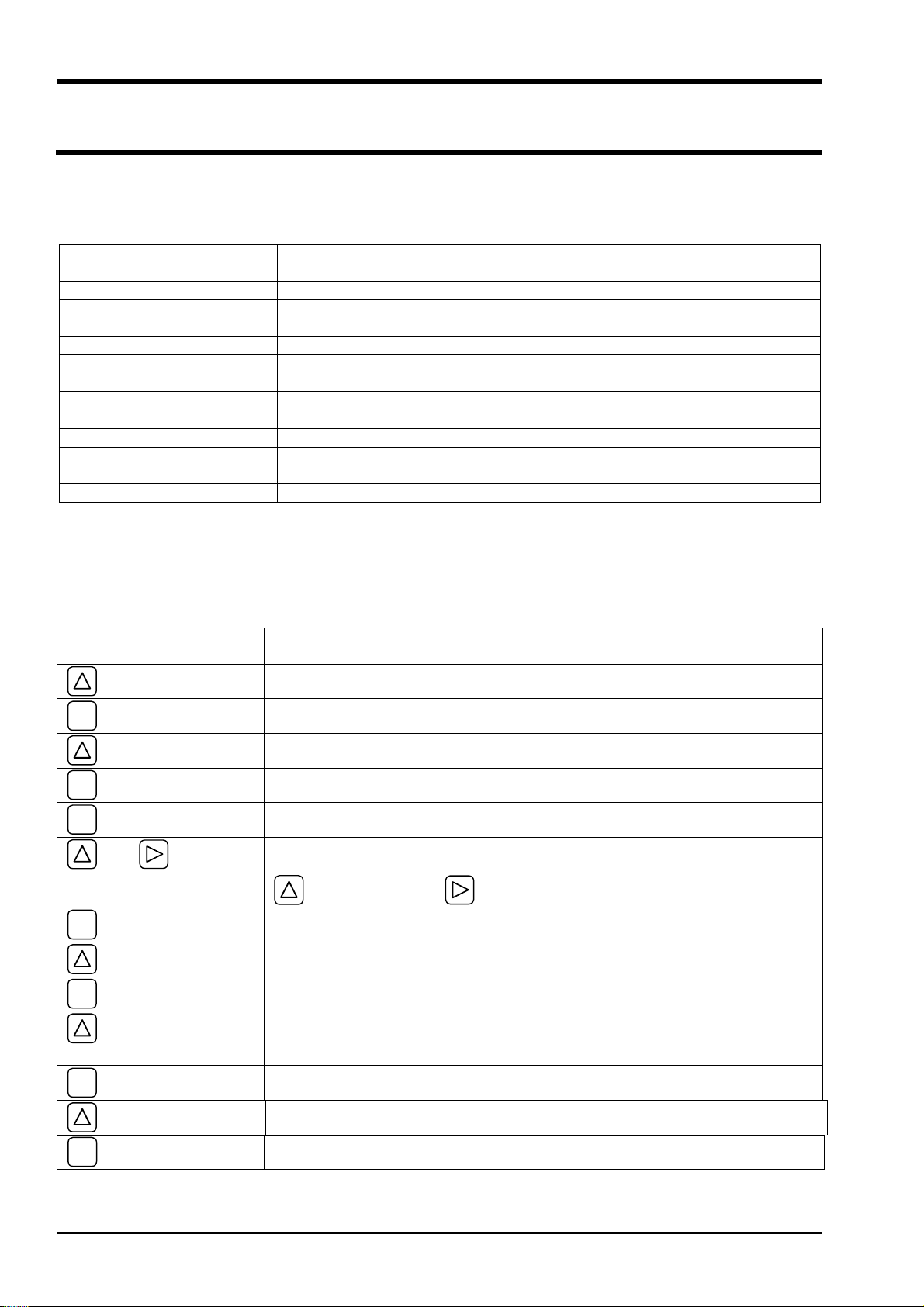
4.2. Configuration of keys
key: key for:
Measurement Mode
Par.
Protection
OUTPUT SETTING
(Section 4.4.1.)
ENT
ESC
key for
Protection ON
Protection OFF
ZERO ADJUST CLEAR
(Section 4.5.1.) SET ZERO
DAMPING (Section 4.5.2.)
CUTOFF (Section 4.5.3.)
DISPLAY
(Section 4.5.4.)
INPUT ID NO
1st.ROW VELOCITY
2nd.ROW VELOCITY
FLOW RATE
FLOW RATE(%)
+TOTAL(ACTUAL)
+TOTAL(PULSE)
–
TOTAL(ACTUAL)
–
TOTAL(PULSE)
FLOW RATE
FLOW RATE(%)
+TOTAL(ACTUAL)
+TOTAL(PULSE)
–
TOTAL(ACTUAL)
–
TOTAL(PULSE)
RANGE
FLOW RATE
(Section 4.5.5.)
TOTAL
(Section 4.5.6.)
FLOW SPAN-1
FLOW SPAN-2
HYSTERESIS
BURNOUT
(CURRENT) HOLD
BURNOUT TIMER
TOTAL MODE
PULSE VALUE
PULSE WIDTH
TOTAL PRESET
OVER SCALE
UNDER SCALE
ZERO
START
STOP
RESET
5.0ms
10.0ms
50.0ms
100.0ms
200.0ms
- 40 -
Page 51

B
ULLETIN F-7
0
DO1 OUT
(Section 4.5.7.)
NOT USED
+TOTAL PULSE
–
FLOW SPAN-2
ALARM
FLOW SWITCH
TOTAL SWITCH
DO2 OUT
(Section 4.5.7.)
OUTPUT COMPENSATION
(Section 4.5.8.)
NOT USED
+TOTAL PULSE
–
FLOW SPAN-2
ALARM
FLOW SWITCH
TOTAL SWITCH
TOTAL PULSE
TOTAL PULSE
BURNOUT(TOTAL)
BURNOUT TIMER
ALL
HARDWARE FAULT
PROCESS ERROR
UPPER SWITCH
LOWER SWITCH
ALL
HARDWARE FAULT
PROCESS ERROR
UPPER SWITCH
LOWER SWITCH
HOLD
COUNT
CONTACT ACTION
CONTACT ACTION
ACTIVE ON
ACTIVE OFF
ACTIVE ON
ACTIVE OFF
MEASURE SETUP
SYSTEM UNIT
(Section 4.6.1.)
FLOW UNIT
(Section 4.6.2.)
TOTAL UNIT
(Section 4.6.3.)
(Section 4.6.4.)
PIPE PARAMETER
(S= )
METRIC
ENGLISH
L/S
L/min
L/h
ML/d
m3/s
etc.
mL
L
m3
km3
Mm3
etc.
OUTER DIAMETER
PIPE MATERIAL
WALL THICKNESS
PVC
PVDF
PEEK
PP
CARBON STEEL
STAINLESS STEEL
COPPER
PIPE S.V
-41-
Page 52

B
ULLETIN F-70
MAINTENANCE
MODE
LINING MATERIAL
For NO LINING
LINING THICKNESS
KIND OF FLUID
KINEMATIC VISCO
SENSOR MOUNTING
SENSOR TYPE
CURRENT
CALIBRATION
CURRENT OUPUT SETTING (Section 4.7.2.)
TOTAL PULSE (Section 4.7.3.)
STATUS OUTPUT
(Section 4.7.4.)
TEST MODE
(Section 4.7.5.)
COMMUNICATION
(Section 4.7.6.)
(Section 4.7.1.)
4mA
20mA
ON
OFF
NOT USED
SETTING
COM.MODE
COM.BAUD RATE
COM.PARITY
COM.STOP BIT
COM.SLAVE NO.
NO LINING
TAR EPOXY
MORTAR
RUBBER
TEFLON
PYREXGLASS
LINING S.V
WATER
SEA WATER
FLUID S.V
V
Z
SX3A/SX3B
SX3C/SX3D
INPUT DATA
TRACKING TIME
RS-232C
RS-485
2400BPS
4800BPS
9600BPS
19200BPS
NON.
ODD
EVEN
1BIT
2BITS
- 42 -
SYNCHRONIZATION
(Section 4.7.7.)
LANGUAGE
(Section 4.7.8.)
REGISTER ID No.
(Section 4.7.9.)
VER. No. (Section 4.7.10.)
EEPROM INITIAL
LCD/LED CHECK
(Section 5.7.1.)
DATA DISPLAY
(Section 5.7.1.)
MASTER
SLAVE
ENGLISH
JAPANESE
GERMAN
FRENCH
SPANISH
Page 53

B
ULLETIN F-7
0
4.3. Initial values of parameters
The following provides factory set values.
No. Setting item Settable range Initial value Settable value
1 Parameter protection 2 menus PROTECTION ONPROTECTION ON,
PROTECTION OFF
2 ID No. 0000 to 9999 0000
3 Unit system 2 menus Metric Metric (metric system),
English (inch system)
4 Flow rate unit
12 menus
m3/h
(Metric system)
12 menus
(Inch system)
5 Total unit
8 menus
3
m
(Metric system)
10 menus
(Inch system)
6 Pipe outer diameter 10.00 to 650mm 60.00mm [mm, in]
7 Pipe material 10 menus
PVC PVC, PVDF, PEEK, PP, CARBON STEEL,
Sound velocity: 1000
to 3700 m/s.
8 Wall thickness 0.1 to 50.00mm 4.50mm [mm, in]
9 Lining material 7 menus
No lining No lining, tar epoxy, mortar, rubber, Teflon,
Sound velocity: 1000
Measurement conditions
to 3700m/s
10 Lining thickness 0.01 to 50.00 ––– [mm, in]
11 Fluid type 3 menus
Water Water, sea water,
Sound velocity:
500 to 2500m/s
12 Kinematic
viscosity
13 Sensor mounting
0.0001 to 999.9999
×10–6m
2
1.0038
/s
×10–6m2/s
2 menus V V, Z
method
14
Sensor type 2 menus Specified by the
12th digit of
type code.
15 Zero adjustment 2 menus Clear
(unadjusted)
16 Damping 0 to 100sec 5sec sec
17 Low flow rate
cutting
18 Display 1st line
contents
19 Display 1st line
decimal point
Output conditions
0 to 5 m/s in terms of
0.150 m3/h [The unit selected at No. 4]
flow velocity
7 menus Flow velocity
(m/s)
00000.000
position
20
Display 2nd line
7 menus Flow rate (m3/h) Flow velocity, flow rate (ACTUAL),
contents
L/s L/min L/h ML/d m3/s m3/min
3
m
/h Mm3/d BBL/s BBL/min
BBL/h MBBL/d
gal/s gal/min gal/h Mgal/d ft
3
ft
/min ft3/h Mft3/d BBL/s BBL/min
BBL/h MBBL/d
mL L m3 km3 Mm3 mBBL BBL
kBBL
gal kgal ft3 kft3 Mft3 mBBL BBL
kBBL ACRE-in ACRE-ft
STAINLESS STEEL, COPPER,
other (sound velocity: ____ [m/s, ft/s])
Pyrexglass,
other (sound velocity: ____ [m/s, ft/s])
other (Sound velocity: [m/s, ft/s])
2
[×10–6m
/s, ft2/s]
SX3A/B, SX3C/D
Set zero, clear (factory set at clear)
Flow velocity, flow rate (ACTUAL),
flow rate (%), forward total,
reverse total, forward total pulse,
reverse total pulse
(move to desired decimal position)
flow rate (%), forward total,
reverse total, forward total pulse,
reverse total pulse
3
/s
-43-
Page 54

B
ULLETIN F-70
No. Setting item Settable range Initial value Settable value
21 Display 2nd line
decimal point
position
00000.000
(move to desired decimal position)
22 Flow span-1 0.3 to 10 m/s in
terms of flow
velocity
23 Flow span-2 0.3 to 10 m/s in
terms of flow
velocity
24 Hysteresis 0 to 10% 5.00% %
25 Burnout 4 menus Hold Hold, upper limit, lower limit, zero
26
27 Total action 3 menus Start Start, stop, reset
28 Pulse value 0.00001 to 9999999 1m3 [The unit selected at No. 5]
29 Total pulse
30 Burnout 2 menus Hold Hold, count
31
32 DO1 output type ż 5 output contents
33 DO1 output action 2 menus ––– ON, OFF
34 DO2 output type ż 5 output contents
35 DO output action 2 menus ––– ON, OFF
36
Analog output
Burnout timer 0 to 100sec 10sec sec
5 menus 5msec 5, 10, 50, 100, 200msec
width
Total output
Burnout timer 0 to 100sec 10sec sec
menus.
ż 3 alarm menus.
ż Flow switch
range 0 to 10 m/s
Output conditions
Span calibration 0 to 200% 100.0% %
in terms of flow
velocity.
ż T otal switch range
0.000001 to
99999999
menus.
ż 3 alarm menus.
ż Flow switch
range 0 to 10 m/s
in terms of flow
velocity.
ż T otal switch range
0.000001 to
99999999
15.0000m3/h [The unit selected at No. 4]
0.0000m3/h [The unit selected at No. 4]
NOT USED
NOT USED
NOT USED
Flow direction
Alarm [all, hard, process]
Flow switches
Upper limit
[ [The unit selected at No. 4]]
Lower limit
[ [The unit selected at No. 4]]
To tal switch
[ [The unit selected at No. 5]]
Unused
Flow direction
Alarm [all, hard, process]
Flow switches
Upper limit
[ [The unit selected at No. 4]]
Lower limit
[ [The unit selected at No. 4]]
Total switch
[ [The unit selected at No. 5]]
- 44 -
Page 55

4.4. Parameter protection
B
0
4.4.1. Parameter protection ON/OFF
Description
Parameters can be protected so that the flow meter settings will not carelessly by mistake.
z
Parameters can be protected by setting the "ID No." (Note) in the maintenance mode.
z
Note: 4 digits are factory set at "0000" (see Section 4.7.9).
Settable range : PROTECTION ON : Parameters cannot be changed.
PROTECTION OFF : Parameters can be changed.
For actual keying, refer to the following examples.
Typical operation Change the parameter protection from ON to OFF (suppose ID No. is "2234").
Keying order Description Indication
Pressed in the measurement mode to indicate [PAR.
PROTECTION].
ź
PAR. PROTECTION
PROTECTION ON
ULLETIN F-7
ENT
ź
ź
ENT
ź
ź
ź
ENT
ź
ź
ź
ENT
--- Parameter protection canceled.---
Pressed to blink the 2nd line.
Pressed to indicate "PROTECTION OFF".
Pressed to indicate “INPUT ID NO.”.
Pressed to indicate "0000" and blink the cursor.
Note: If ID No. is "0000" (as factory set), press
key to release the parameter protection.
Pressed until ID No. [2234] is composed.
Pressed.
* If ID No. does not coincide, "INPUT ERROR!"
appears, and the input screen is resumed.
ENT
PAR. PROTECTION
PROTECTION ON
PAR. PROTECTION
PROTECTION OFF
PAR. PROTECTION
½½
COMPLETE
Ļ
INPUT ID NO
½½½½
INPUT ID NO
0000
INPUT ID NO
2234
ID NO INPUT
½½
COMPLETE
Ļ
PAR. PROTECTION
PROTECTION OFF
½½
½½
-45-
Page 56

B
ULLETIN F-70
4.5. Output setup mode
4.5.1. Adjusting zero point
Description
Zero point is calibrated.
z
Settable range
CLEAR: Clears the zero point calibration value to "0". Used in case the flow cannot be stopped when
calibrating the zero point.
Note: 1. When possible, stop the flow and carry out "SET ZERO" stated below. Otherwise, an
error may occur in the zero point.
SET ZERO: A point where "SET ZERO" is carried out is regarded as zero. Used for calibrating the zero point
upon stopping the flow.
Note: 2. The flow must completely be stopped. Otherwise, the flowing status is regarded as zero,
thereby causing an error.
For actual keying, refer to the typical operation indicated below. Set the parameter protection to OFF beforehand
(Section 4.4.1).
Typical operation Completely fill the piping, close the upstream and downstream valves, and proceed to zero point
calibration.
Keying order Description Indication
Pressed twice to indicate "OUTPUT SETUP".
OUTPUT SETUP
ESC
ź
ENT
ź
ź
ENT
ź
ź
ź
ź
Press
Pressed twice to indicate "ZERO ADJUST" and blink the
cursor.
Pressed to select "SET ZERO".
Pressed to execute "SET ZERO".
* Be sure to completely stop the flow beforehand.
--- Zero point calibrated.---
ESC
key once, and
the measurement mode.
key 3 times to resume
ZERO ADJUST
CLEAR
ZERO ADJUST
SET ZERO
ZERO ADJUST
½½
COMPLETE
Ļ
ZERO ADJUST
SET ZERO
0.000 m/s
0.000 m3/h
½½
- 46 -
Page 57

B
ULLETIN F-7
0
4.5.2. Setting the damping
Description
Used for smoothing the variation of measured value.
z
A time constant is set (response time of about 63%).
Settable range: 0 to 100 sec in 1 sec steps.
Note: In case 0 sec. is set, response time becomes:
• System cycle: 0.2 sec
• Dead time: less than 0.2 sec
• Time constant: 0.1 sec
For actual keying, refer to the typical operation indicated below. Set the parameter protection to OFF beforehand
(Section 4.4.1).
Typical operation Change the damping from 5 to 20 sec.
Keying order Description Indication
Pressed twice to indicate "OUTPUT SETUP".
ź
OUTPUT SETUP
ESC
ENT
ź
ź
ENT
ź
ź
ENT
ź
ź
ź
ź
Pressed to indicate "ZERO ADJUST".
Pressed to indicate "DAMPING".
Pressed to blink the cursor.
Operated to select "20".
Pressed to register it.
--- Damping registered.---
Press
ESC
key once, and
the measurement mode.
key 3 times to resume
ZERO ADJUST
SET ZERO
DAMPING
5 sec
DAMPING
005 sec
DAMPING
020 sec
DAMPING
½½
COMPLETE
Ļ
DAMPING
20 sec
0.000 m/s
0.000 m3/h
½½
-47-
Page 58

B
ULLETIN F-70
4.5.3. Setting the low flow rate cutting
Description
The output can be cut when the flow rate is too
z
Effective for indication, analog output (4-20 mA) and total
z
low.
Output
operation.
Settable range: 0 to 5 [m/s] in terms of flow velocity
(factory set at 0.150 [m
3
/h]).
Notes
1. As required, set the low flow rate cut because the flow meter
may read a flow rate when the fluid in the piping is moving
on account of convection, etc. even if the valves are closed.
2. The flow rate unit is as selected by "FLOW UNIT" in
"MEASURE SETUP" (see Section 4.6.2).
actual keying, refer to the typical operation indicated below. Set the parameter protection to OFF beforehand
For
Low flow rate cut setting value
(Section 4.4.1).
3
Typical operation Set the low flow rate cut point to 0.5 [m
/h].
Keying order Description Indication
Pressed twice to indicate "OUTPUT SETUP".
OUTPUT SETUP
ź
ENT
Pressed to indicate "ZERO ADJUST".
ZERO ADJUST
SET ZERO
ź
Flow rate
ESC
ź
ENT
ź
ź
ENT
ź
ź
ź
ź
Press
Pressed twice to indicate "CUTOFF".
Pressed to blink the cursor.
Operated to compose "0.5".
Pressed to register it.
--- CUTOFF registered.---
ESC
key once, and
key 3 times to resume
the measurement mode.
CUTOFF
0.0010 m3/h
CUTOFF
0000.0010 m3/h
CUTOFF
0000.5000 m3/h
CUTOFF
½½
COMPLETE
Ļ
CUTOFF
0.500 m3/h
0.000 m/s
0.000 m3/h
½½
- 48 -
Page 59

B
ULLETIN F-7
0
4.5.4. Setting the LCD indication
Description
Flow velocity indication
z
Selectable flow velocity units : m/s (if SYSTEM UNIT was set to METRIC)
: ft/s (if SYSTEM UNIT was set to ENGLISH) (Section 4.6.1).
Note: 1. The decimal point position is fixed.
Flow rate indication
z
Selectable flow rate indications: Actual value reading, % reading.
Note: 2. The indication unit is as selected by FLOW UNIT (Section 4.6.2).
Total indication
z
Selectable total indications: Actual total value reading (forward/reverse flow), total pulse count (forward/reverse
flow).
Note: 3. When total unit is changed, perform “RESET”. (Refer to item 4.5.6)
Conversion of totalizer memory contents due to unit change is not automatic.
How to verify the indication
z
Set the DISPLAY setting mode to 1st. ROW (for indication on 1st line) or 2nd. ROW (for indication on 2nd line),
and then select indication contents.
For actual keying, refer to the typical operation indicated below. Set the parameter protection to OFF beforehand
(Section 4.4.1).
Typical operation Set the LCD indication on 1st line to % reading.
Keying order Description Indication
Pressed twice to indicate "OUTPUT SETUP".
OUTPUT SETUP
ź
ENT
ź
ź
ENT
ź
ENT
ź
ź
ENT
ź
ź
ENT
ź
ź
ź
ź
Pressed to indicate "ZERO ADJUST".
Pressed 3 times to indicate "DISPLAY".
Pressed to blink the cursor.
Pressed again to select "1st. ROW".
Pressed twice to select "FLOW RATE (%)".
Pressed to enter "FLOW RATE (%)" and indicate "1st.
ROW DIGIT".
Pressed to shift the decimal point position to next place.
Pressed to register it.
--- FLOW RATE (%) indication validated.---
ZERO ADJUST
CLEAR
DISPLAY
1ST. ROW
DISPLAY
1ST. ROW
1ST. ROW
VELOCITY
1ST. ROW
FLOW RATE (%)
1ST. ROW DIGIT
½½½½.½½
1ST. ROW DIGIT
½½½½½.½
1ST. ROW DIGIT
½½
COMPLETE
½½
Ļ
1ST. ROW
FLOW RATE (%)
ESC
Press
ESC
key 2 times, and
resume the measurement mode
key 3 times to
0.0 %
0.000 m3/h
-49-
Page 60

B
ULLETIN F-70
4.5.5. Setting the flow rate and flow velocity range
4.5.5.1. Setting the flow rate range (single range FLOW SPAN-1)
Description
The range (full scale) of flow rate to measure is set.
z
* The analog output (4-20 mA) corresponds to the range setting.
After changing the range, adjust zero point (see Section 4.5.1.).
z
Settable range: 0.3 to 10 [m/s] in terms of flow velocity in piping.
z
20mA
SPAN-1
* Piping parameters and FLOW UNIT must be set beforehand.
* If a value beyond the settable range is inputted, "INPUT ERROR" appears
and then last setting is resumed.
* If "piping parameters" or "FLOW UNIT" has been changed after setting
the range, recommence the range setting.
4mA
0 100%
Flow rate
Note: 1. The flow rate unit is as selected by "FLOW UNIT" in the "MEASURE SETUP" mode (see Section 4.6.2.).
For concrete keying, refer to the typical operation indicated below. Set the parameter protection to OFF beforehand
(Section 4.4.1).
Typical operation Set the "FLOW SPAN-1" to 60 m3/h.
* Set the piping parameters and "FLOW UNIT" beforehand.
Keying order Description Indication
Pressed twice to indicate "OUTPUT SETUP".
OUTPUT SETUP
ź
ENT
Pressed to select the ZERO ADJUST mode.
ZERO ADJUST
CLEAR
ź
ź
ENT
ź
ENT
ź
ENT
ź
ź
ź
ENT
ź
ź
ź
ź
Pressed 4 times to indicate "RANGE".
Pressed to blink the cursor.
Pressed to indicate "FLOW SPAN-1".
Pressed to blink the cursor.
Pressed repeatedly until the cursor is positioned at "1".
Pressed 5 times to select "6".
Note: To change the decimal point position, align the
cursor
to desired position and then press the
key.
Pressed to register it.
--- SPAN-1 registered.---
RANGE
FLOW RATE
RANGE
FLOW RATE
FLOW SPAN-1
0000010.0 m3/h
FLOW SPAN-1
0000010.0 m3/h
FLOW SPAN-1
0000010.0 m3/h
FLOW SPAN-1
0000060.0 m3/h
FLOW SPAN-1
½½
COMPLETE
Ļ
FLOW SPAN-1
60.0 m3/h
½½
ESC
- 50 -
Press
ESC
key 3 times and press
resume the measurement mode.
key 3 times to
0.000 m/s
0.000 m3/h
Page 61

4.5.5.2. Setting forward automatic 2 ranges
B
0
ULLETIN F-7
Description
The function carries out a measurement while changing over
z
20mA
the range according to the flow rate.
The current output changes with the action range as
z
illustrated on the right.
The hysteresis can be set to between 0 and 10% of the
z
SPAN-1
SPAN-2
smaller range.
Upon setting DO1 or DO2 to "FLOW SPAN-2", a contact
z
outputs "SPAN-2" action. Select [ACTIVE ON] or
[ACTIVE OFF] separately
(see Section 4.5.7.3.).
After changing the range value, adjust zero point
z
4mA
Hysteresis
(see Section 4.5.1.).
Settable range: 0.3 to 10 [m/s] in terms of flow velocity in piping for any of SPAN-1 and SPAN-2.
z
* The piping parameters
and FLOW UNIT
must be set beforehand.
* If a value beyond the settable range is inputted, "INPUT ERROR" appears and then last setting is resumed.
* If "FLOW UNIT" has been changed after setting the range, set the range setting again.
* When FLOW SPAN-2 is not used (in the case of single range), set “0” for FLOW SPAN-2.
Note: 1. The flow rate unit is as selected by "FLOW UNIT". Before setting range, set the "FLOW UNIT"
(see Section 4.6.2.).
For actual keying, refer to the typical operation indicated below. Set the parameter protection to OFF beforehand
(Section 4.4.1).
3
Typical operation Set "FLOW SPAN-1" to 10 [m
/h], "FLOW SPAN-2" to 60 [m3/h], and "HYSTERESIS" to 7%.
* Set the piping parameters and "FLOW UNIT" beforehand.
Keying order Description Indication
Pressed twice to indicate "OUTPUT SETUP".
OUTPUT SETUP
ź
ENT
ź
ź
ENT
ź
ENT
ź
ENT
ź
ź
ź
Pressed to indicate "ZERO ADJUST".
Pressed 4 times to indicate "RANGE".
Pressed to blink the cursor.
Pressed to indicate "FLOW SPAN-1".
Pressed to blink the cursor on 2nd line.
Pressed repeatedly until the cursor is positioned at "2".
Pressed repeatedly until "1" appears.
Note: To change the decimal point position, align the
cursor with a place to change to, and press
key likewise.
ZERO ADJUST
CLEAR
RANGE
FLOW RATE
RANGE
FLOW RATE
FLOW SPAN-1
20.0000 m3/h
FLOW SPAN-1
0020.0000 m3/h
FLOW SPAN-1
0020.0000 m3/h
FLOW SPAN-1
0010.0000 m3/h
ENT
ź
Pressed to register it.
FLOW SPAN-1
½½
COMPLETE
½½
Ļ
-51-
Page 62

B
ULLETIN F-70
ź
ź
ź
ź
ENT
ź
ź
ź
ENT
ź
ź
ź
ź
ź
--- FLOW SPAN-1 registered.---
Pressed to indicate "FLOW SPAN-2".
Pressed to blink the cursor.
Pressed twice to move the cursor.
Pressed 6 times to select "6".
Pressed to register it.
--- FLOW SPAN-2 registered.---
Pressed to indicate "HYSTERESIS".
FLOW SPAN-1
10.0000 m3/h
FLOW S
PAN-2
0.0000 m3/h
FLOW SPAN-2
0000.0000 m3/h
FLOW SPAN-2
0000.0000 m3/h
FLOW SPAN-2
0060.0000 m3/h
FLOW SPAN-2
½½
COMPLETE
Ļ
FLOW SPAN-2
60.0000 m3/h
HYSTERESIS
5.00 %
½½
ESC
ENT
ź
ź
ź
ENT
ź
ź
ź
ź
Press
Pressed to blink the cursor.
Pressed to move the cursor.
Pressed twice to select "7".
Pressed to register it.
--- HYSTERESIS registered.---
ESC
key 3 times, and press
resume the measurement mode.
key 3 times to
HYSTERESIS
05.00 %
HYSTERESIS
05.00 %
HYSTE
RESIS
07.00 %
HYSTERESIS
½½
COMPLETE
Ļ
HYSTERESIS
7.00 %
0.000 m/s
0.000 m3/h
½½
- 52 -
Page 63

4.5.5.3. Setting forward/reverse automatic 2 ranges
B
0
ULLETIN F-7
Description
The function measures the flow rate of either forward or reverse
z
20mA
flow while changing over the range corresponding to th e flow
direction.
The current output changes with the action range as illustrated on
z
the right.
The hysteresis can be set to between 0 and 10% of the action
z
4mA
range.
Upon setting DO1 or DO2 to "FLOW SPAN-2", a contact outputs
z
"SPAN-2" action. Select [ACTIVE ON] or [ACTIVE OFF]
separately (see Section 4.5.7.3.).
After changing the range value, adjust zero point (see Section 4.5.1.).
z
Settable range: r0.3 to 10 [m/s] in terms of flow velocity in piping for any of SPAN-1 and SPAN-2.
z
* The piping parameters
and FLOW UNIT must be set beforehand.
* If a value beyond the settable range is inputted, "INPUT ERROR" appears and then last setting is resumed.
* If "FLOW UNIT" has been changed after setting the range,
* When FLOW SPAN-2 is not used (in the case of single range), set “0”
set the range setting again.
for FLOW SPAN-2.
Note: 1. The flow rate unit is as selected by "FLOW UNIT in the "MEASUREMENT SETUP" mode. Before
range setting, set the "FLOW UNIT" (see Section 4.6.2.).
For
actual keying, refer to the typical operation indicated below. Set the parameter protection to OFF beforehand
(Section 4.4.1).
3
Typical operation Set "FLOW SPAN-1" to 20 [m
/h], "FLOW SPAN-2" to -10 [m3/h], and "HYSTERESIS" to 7%.
* Set the piping parameters and "FLOW UNIT" beforehand.
Keying order Description Indication
Pressed twice to indicate "OUTPUT SETUP".
OUTPUT SETUP
Hysteresis
ź
ENT
ź
ź
ENT
ź
ENT
ź
ENT
ź
ź
ź
Pressed to indicate "ZERO ADJUST".
Pressed 4 times to indicate "RANGE".
Pressed to blink the cursor.
Pressed to indicate "FLOW SPAN-1".
Pressed to blink the cursor.
Pressed repeatedly until the cursor is positioned at "5".
Pressed repeatedly until "2" appears.
Note: To change the decimal point position, align the
cursor with a place to change to, and press
key likewise
ZERO ADJUST
CLEAR
RANGE
FLOW RATE
RANGE
FLOW RATE
FLOW SPAN-1
50.0000 m3/h
FLOW SPAN-1
0050.0000 m3/h
FLOW SPAN-1
0050.0000 m3/h
FLOW SPAN-1
0020.0000 m3/h
ENT
ź
Pressed to register it.
FLOW SPAN-1
½½
COMPLETE
½½
Ļ
-53-
Page 64

B
ULLETIN F-70
ź
ź
ź
ź
ENT
ź
ź
ź
ź
ENT
ź
ź
ź
ź
--- FLOW SPAN-1 registered.---
Pressed to indicate "FLOW SPAN-2".
Pressed to blink the cursor.
Pressed repeatedly until "–" appears on 1st place.
Pressed twice to move the cursor.
Pressed to select "1".
Pressed to register it.
--- FLOW SPAN-2 registered.---
FLOW SPAN-1
20.0000 m3/h
FLOW SPAN-2
0.0000 m3/h
FLOW SPAN-2
0000.0000 m3/h
FLOW SPAN-2
–000.0000 m3/h
FLOW SPAN-2
–000.0000 m3/h
FLOW SPAN-2
–010.0000 m3/h
FLOW SPAN-2
½½
COMPLETE
Ļ
FLOW SPAN-2
–10.0000 m3/h
½½
ESC
ź
ENT
ź
ź
ź
ENT
ź
ź
ź
ź
Press
Pressed to indicate "HYSTERESIS".
Pressed to blink the cursor.
Pressed to move the cursor.
Pressed twice to select "7".
Pressed to register it.
--- HYSTERESIS registered.---
ESC
key 3 times, and press
resume the measurement mode.
key 3 times to
HYSTERESIS
5.00 %
HYSTERESIS
05.00 %
HYSTERESIS
05.00 %
HYSTER
ESIS
07.00 %
HYSTERESIS
½½
COMPLETE
Ļ
HYSTERESIS
7.00 %
0.000 m/s
0.000 m3/h
½½
- 54 -
Page 65

B
ULLETIN F-7
0
4.5.5.4. How to set analog output at error (BURNOUT)
Description
Determine how to set the analog output when received wave error, etc. due to device error, accidental drain of
z
piping or ingress of bubbles.
Settable ranges
z
(1) Analog output (4-20 mA) at error
HOLD (factory set): Outputs a current intensity preceding the error.
OVER SCALE: Outputs 23.2 mA.
UNDER SCALE: Outputs 0.8 mA.
ZERO: Outputs 4 mA.
(2) BURNOUT TIMER (time from error detection to BURNOUT processing) 0 to 100 seconds (factory set at 10
sec).
For actual keying, refer to the typical operation indicated below. Set the parameter protection to OFF beforehand
(Section 4.4.1).
Typical operation Set the BURNOUT to "OVER SCALE".
Set the BURNOUT TIMER to "20 sec".
* Set the piping parameters and "FLOW UNIT" beforehand.
Keying order Description Indication
Pressed twice to indicate "OUTPUT SETUP".
OUTPUT SETUP
ź
ENT
ź
ź
ENT
ź
ENT
ź
ź
ENT
ź
ź
Pressed to indicate "ZERO ADJUST".
Pressed 4 times to indicate "RANGE".
Pressed to blink the cursor.
Pressed to indicate "FLOW SPAN-1".
Pressed 3 times to indicate the BURNOUT (CURRENT).
Pressed to blink the 2nd line.
Pressed to indicate "OVER SCALE".
ZERO ADJUST
CLEAR
RANGE
FLOW RATE
RANGE
FLOW RATE
FLOW SPAN-1
20.0000 m3/h
BURNOUT (CURRENT)
HOLD
BURNOUT (CURRENT)
HOLD
BURNOUT (CURRENT)
OVER SCALE
ENT
ź
Pressed to register it.
BURNOUT (CURRENT)
½½
COMPLETE
Ļ
½½
ź
ź
ź
--- “OVER SCALE” registered.---
Pressed to indicate "BURNOUT TIMER".
BURNOUT (CURRENT)
OVER SCALE
BURNOUT TIMER
10 s
ź
ENT
Pressed to blink the cursor.
BURNOUT TIMER
010 s
ź
-55-
Page 66

B
ULLETIN F-70
ESC
ź
ź
ENT
ź
ź
ź
ź
Press
Pressed to align the cursor with "1".
Pressed to select "2".
Pressed to register it.
--- “BURNOUT TIMER” registered.---
ESC
key 3 times and press
resume the measurement mode.
key 3 times to
BURNOUT TIMER
010 s
BURNOUT TIMER
020 s
BURNOUT TIMER
½½
COMPLETE
Ļ
BURNOUT TIMER
20 s
0.000 m/s
0.000 m3/h
½½
- 56 -
Page 67

B
ULLETIN F-7
0
4.5.6. Setting the total
4.5.6.1. Setting the total pulse (pulse value, pulse width)
Description
Set for totalizing a process variable (flow rate) by total meter, etc. according to total pulse output.
z
Pulse value: Total amount (volume) per pulse.
z
A pulse is outputted when the total volume has attained an amount set by the pulse value, and adds to the total pulse
count (in case of total pulse indication).
Settable range: 0.000001 to 99999999.
* Set the total unit before setting the pulse value (see Section 4.6.3.).
Pulse width: Width of total pulse output.
z
Select a pulse width according to a corresponding total meter out of menus.
Settable range: 5 ms, 10 ms, 50 ms, 100 ms, 200 ms.
Note: If the output is through DO2 (relay contact), select 50 ms or longer (see Section 4.5.7.).
Restrictions in the setup
z
Output of total pulses involves the following restrictions depending on the DO output port (DO1, DO2).
DO output port
DO1: Transistor open collector
DO2: Relay contact 1 pulse per day to 1 pulse per second 50ms, 100ms, 200ms
The maximum output frequency is restricted by the setup of the pulse width.
Therefore, set the pulse width and pulse value so that both condition 1 and condition 2 indicated below are
satisfied.
Correct results may not occur if the setup does not satisfy both condition 1 and condition 2.
Condition 1:
1 FLOW SPAN-1
86400
[Hz]
Condition 2:
FLOW SPAN-1
PULSE VALUE [m
Note 1: The range of FLOW SPAN-1 or FLOW SPAN-2, whichever is larger, is the object in the case of 2-range setup.
Note 2: Restrictions in the maximum output frequency of each output port will occur when the flow rate exceeds
the set range. If the unit is programmed such that the maximum frequency occurs at 100% of flow rate,
totalizer function pulses may be incapable of following the flow rate's required pulsing action for correct
totalizer indication and process measurement. Solution:
can accomodate the expected process 100% flow rate scale resulting pulsing action.
PULSE VALUE [m
Note 1) [m3
3
]
Pulse output frequency range
(at the time of full scale flow rate)
1 pulse per day to 100 pulses per
second
Note 1) [m3
/s] 1000
2u PULSE WIDTH [ms]
/s] 100 [Hz] (case of DO1)
3
]
1 [Hz] (case of DO2)
ensure the user programmed DO output pulse rate
Pulse width
5ms, 10ms, 50ms, 100ms, 200ms
-57-
Page 68

B
ULLETIN F-70
Typical calculation
Calculate the range that permits setup of the pulse value under the range (FLOW SPAN-1) and pulse width indicated
below.
When set values of the range (FLOW SPAN-1) and pulse width are as follows;
FLOW SPAN-1: 36 [m
i) Case of DO1 output
From condition 1,
3
/h] (=0.01 [m3/s]), PULSE WIDTH: 50 [ms]
3
/s] 0.01 [m3/s]
=
100 [Hz]
= 0.0001 [m3] = 0.1[L]
PULSE VALUE
PULSE VALUE
FLOW SPAN-1 [m
100 [Hz]
FLOW SPAN-1[m3/s]u 86400 [s] = 0.01 [m3/s]u 86400 [s] = 864 [m3]
From the above:
0.1 [L]
PULSE VALUE
864 [m3]·····················A
From condition 2,
PULSE VALUE
FLOW SPAN-1 [m3/s]
2u PULSE WIDTH [ms] 2 u 50 [ms]
u
1000
= 0.01 [m
3
/s]
u
= 0.001 [m3] = 1 [L]··········································B
The settable range of the pulse value that satisfies both condition 1 and condition 2 is as follows from results
of calculation A and B:
1 [L]
PULSE VALUE
864 [m3]
ii) Case of DO2 output
From condition 1,
3
/s] 0.01 [m3/s]
=
1 [Hz]
= 0.01 [m3] = 10 [L] ······················C
PULSE VALUE
FLOW SPAN-1 [m
1 [Hz]
1000
Condition 2 is same as that of the case of DO1 output indicated above.
Therefore, the settable range of the pulse value is as follows from results of calculation B and C:
10 [L]
For
actual keying, refer to the typical operation indicated in the next page. Set the parameter protection to OFF
PULSE VALUE
864 [m3]
beforehand (Section 4.4.1).
- 58 -
Page 69

B
ULLETIN F-7
0
Typical operation Set the pulse value to 0.1 m
3
/pulse, and the pulse width to 50 ms.
* Set the total unit beforehand.
Keying order Description Indication
Pressed twice to indicate "OUTPUT SETUP".
OUTPUT SETUP
ź
ENT
Pressed to indicate "ZERO ADJUST".
ZERO ADJUST
CLEAR
ź
Pressed 4 times to indicate "RANGE".
RANGE
FLOW RATE
ź
ENT
Pressed to blink the cursor.
RANGE
FLOW RATE
ź
Pressed to indicate "TOTAL" on 2nd line.
RANGE
TOTAL
ź
ENT
Pressed to indicate "TOTAL MODE".
TOTAL MODE
START
ź
Pressed to indicate "PULSE VALUE".
PULSE VALUE
1 m3
ź
ENT
ź
ź
ź
ENT
ź
ź
ź
ź
ź
ENT
ź
ź
Pressed to indicate the cursor.
Pressed 7 times to move the cursor.
Pressed 9 times to indicate the decimal point.
Pressed to register.
--- “PULSE VALUE” registered.---
Pressed to indicate the PULSE WIDTH.
Pressed to blink the cursor.
Pressed twice to select "50.0 msec".
PULSE VALUE
000000001 m3
PULSE VALUE
000000001 m3
PULSE VALUE
0000000.1 m3
PULSE VALUE
½½
COMPLETE
Ļ
PULSE VALUE
0.1 m3
PULSE WIDTH
5.0 msec
PULSE WIDTH
5.0 msec
PULSE WIDTH
50.0 msec
½½
ENT
ź
Pressed to register it.
PULSE WIDTH
½½
COMPLETE
½½
Ļ
ź
ESC
ź
ź
Press
--- “PULSE WIDTH” registered.---
ESC
key 3 times, and
key 3 times to
PULSE WIDTH
50.0 msec
0.000 m/s
0.000 m3/h
resume the measurement mode.
-59-
Page 70

B
ULLETIN F-70
4.5.6.2. Setting the preset value
Description
Preset value: Value which appears on the total counter when the total value has been reset.
z
Settable range: 0 to 99999999
Notes
1. A resetting action simultaneously resets both forward total memory and reverse total memory.
2. Set the total unit beforehand in the MEASURE SETUP mode (see Section 4.6.3.).
Total value
Reset
For
actual keying, refer to the typical operation indicated below. Set the parameter protection to OFF beforehand
(Section 4.4.1)
Typical operation Set the preset value to 100 m
* Set the total unit beforehand.
Keying order Description Indication
Pressed twice to indicate "OUTPUT SETUP".
Reset
3
.
Reset
Preset value
Time
OUTPUT SETUP
ESC
ź
ENT
ź
ź
ENT
ź
ź
ENT
ź
ź
ENT
ź
ź
ź
ENT
ź
ź
ź
ź
Pressed to indicate "ZERO ADJUST".
Pressed 4 times to indicate "RANGE".
Pressed to blink the cursor.
Pressed to indicate "TOTAL" on 2nd line.
Pressed to indicate "TOTAL MODE".
Pressed 3 times to indicate "TOTAL PRESET".
Pressed to indicate the cursor.
Pressed 6 times to move the cursor.
* Note that input cannot be entered on the firsr digit (the
leftmost digit).
Pressed to select "1".
Pressed to register it.
--- PRESET value registered.---
Press
ESC
key 3 times, and
key 3 times to
resume the measurement mode.
ZERO ADJUST
CLEAR
RANGE
FLOW RATE
RANGE
FLOW RATE
RANGE
TOTAL
TOTAL MODE
START
TOTAL PRESET
0 m3
TOTAL PRESET
000000000 m3
TOTAL PRESET
000000000 m3
TOTAL PRESET
000000100 m3
TOTAL PRESET
½½
COMPLETE
Ļ
TOTAL PRESET
100 m3
0.000 m/s
0.000 m3/h
½½
- 60 -
Page 71

B
ULLETIN F-7
0
4.5.6.3. TOTAL mode (total reset, start, stop)
Description
The total is started, stopped or reset.
z
Settable range: START, STOP, RESET.
z
START: Carried out the total.
STOP: Stops the total.
RESET: Reset the total memory to the preset value.
Notes
1. A resetting action simultaneously resets both forward total memory and reverse total memory.
2. To start a total after resetting a total value, be sure to set the "START"
For actual keying, refer to the typical operation indicated below. Set the parameter protection to OFF beforehand
(Section 4.4.1).
Typical operation Reset the total value (preset value 0 m3), and restart a total.
Keying order Description Indication
.
0.00 m3/h
+ 127.26 m3
ź
ENT
ź
ź
ENT
ź
ź
ENT
ź
ENT
ź
ź
Pressed twice to indicate "OUTPUT SETUP".
Pressed to indicate "ZERO ADJUST".
Pressed 4 times to indicate "RANGE".
Pressed to blink the cursor.
Pressed to indicate "TOTAL" on 2nd line.
Pressed to indicate "TOTAL MODE".
Pressed to blink the cursor.
Pressed twice to indicate "RESET".
OUTPUT SETUP
ZERO ADJUST
CLEAR
RANGE
FLOW RATE
RANGE
FLOW RATE
RANGE
TOTAL
TOTAL MODE
START
TOTAL MODE
START
TOTAL MODE
RESET
ENT
ź
Pressed to execute "RESET".
Note: After resetting,
. To resume a total, execute "START".
stops
the total operation automatically
TOTAL MODE
½½
COMPLETE
½½
Ļ
ź
ź
ź
ENT
--- RESET has ended.---
Pressed to blink the cursor.
TOTAL MODE
STOP
TOTAL MODE
STOP
ź
Pressed twice to indicate "START".
TOTAL MODE
START
ź
-61-
Page 72

B
ULLETIN F-70
ENT
Pressed to start a total operation.
TOTAL MODE
½½
COMPLETE
ź
ź
ESC
ź
ź
Press
--- Total operation has started.---
ESC
key 3 times, and
key 3 times to
TOTAL MODE
START
0.00 m3/h
+ 0.00 m3
resume the measurement mode.
4.5.6.4. Determining how to handle total at error (BURNOUT)
Description
BURNOUT(TOTAL)
Determines how to
z
interior or bubbles mixed in fluid (common to total indication and total pulse output).
Settable range
z
HOLD: Stops the total (
COUNT: Continues the total according to
BURNOUT TIMER
Sets the time from error occurrence
z
Settable range: 0 to 100 sec (factory set at 10 sec).
z
The total continues until the burnout timer is actuated.
handle the total function when the measurement status is abnormal on account of an empty pipe
default seting).
the flow rate prior to abnormal status indication.
(abnormal condition - LED red) to error processing.
½½
Ļ
For
actual keying, refer to the typical operation indicated below. Set the parameter protection to OFF beforehand
(Section 4.4.1).
Typical operation Change the processing from "COUNT" to "HOLD", and change the burnout timer setting from 10
seconds to 15 seconds.
Keying order Description Indication
Pressed twice to indicate "OUTPUT SETUP".
OUTPUT SETUP
ź
ENT
Pressed to indicate "ZERO ADJUST".
ZERO ADJUST
CLEAR
ź
Pressed 4 times to indicate "RANGE".
RANGE
FLOW RATE
ź
ENT
Pressed to blink the cursor.
RANGE
FLOW RATE
ź
Pressed to indicate "TOTAL" on 2nd line.
RANGE
TOTAL
ź
ENT
Pressed to indicate "TOTAL MODE".
TOTAL MODE
START
ź
- 62 -
ź
ENT
ź
Pressed 4 times to indicate "BURNOUT (TOTAL)".
Pressed to blink the cursor.
BURNOUT (TOTAL)
COUNT
BURNOUT (TOTAL)
COUNT
Page 73

B
ULLETIN F-7
0
ź
ENT
ź
ź
ź
ź
ź
ENT
ź
ź
ź
ENT
ź
ź
ź
ź
Pressed to indicate "HOLD".
Pressed to register "HOLD".
--- "HOLD" registered.---
Pressed to indicate "BURNOUT TIMER".
Pressed to blink the cursor.
Pressed twice to move the cursor.
Pressed 5 times to select "5".
Pressed to register it.
--- “BURNOUT TIMER” registered.---
BURNOUT (TOTAL)
HOLD
BURNOUT (TOTAL)
½½
COMPLETE
Ļ
BURNOUT (TOTAL)
HOLD
BURNOUT TIMER
10 s
BURNOUT TIMER
010 s
BURNOUT TIMER
010 s
BURNOUT TIMER
015 s
BURNOUT TIMER
½½
COMPLETE
Ļ
BURNOUT TIMER
015 s
½½
½½
ESC
Press
ESC
key 3 times, and
resume the measurement mode.
key 3 times to
0.00 m3/h
+ 0.00 m3
-63-
Page 74

B
ULLETIN F-70
4.5.7. Setting the DO output
Description
Selects the output of total pulses and statuses (alarm, flow switch, total switch, etc.).
Settable ranges (common to DO1 and DO2)
NOT USED : Do not use the contact output.
+TOTAL PULSE : Output the forward total pulses.
–TOTAL PULSE : Output the reverse total pulses.
FLOW SPAN-2 : Select a contact output at SPAN-2 measurement status (forward automatic 2 ranges,
forward/reverse automatic 2 ranges).
ALARM
HARDWARE : Select a contact output at EEPROM error.
PROCESS : Select a contact output when wave is not received or is unstable.
FLOW SWITCH
UPPER SWITCH : Select a contact output when flow rate is above the setting.
LOWER SWITCH : Select a contact output when flow rate is below the setting.
TOTAL SWITCH : Select a contact output when total value exceeds the setting.
CONT ACT ACTION
ACTIVE ON : Normally OFF (DO1) or normally open (DO2).
ACTIVE OFF : Normally ON (DO1) or normally closed (DO2).
Note: DO output specifications
DO1 : Open collector, contact capacity 30 V DC, 0.1 A.
When total pulse output is selected (See 4.5.6.1)
1 pulse/day to 100 pulses/s (at full scale flow rate).
Pulse width: 5, 10, 50, 100 or 200 ms.
DO2 : Relay contact, contact capacity 220 V AC/30 V DC, 1 A.
Life ... 200,000 operations (under rated load), replaceable with socket.
When total pulse output is selected (See 4.5.6.1)
1 pulse/day to 1 pulse/s (at full scale flow rate).
Pulse width: 50, 100 or 200 ms.
For actual keying, refer to the typical operation indicated below. Set the parameter protection to OFF beforehand
(Section 4.4.1).
- 64 -
Page 75
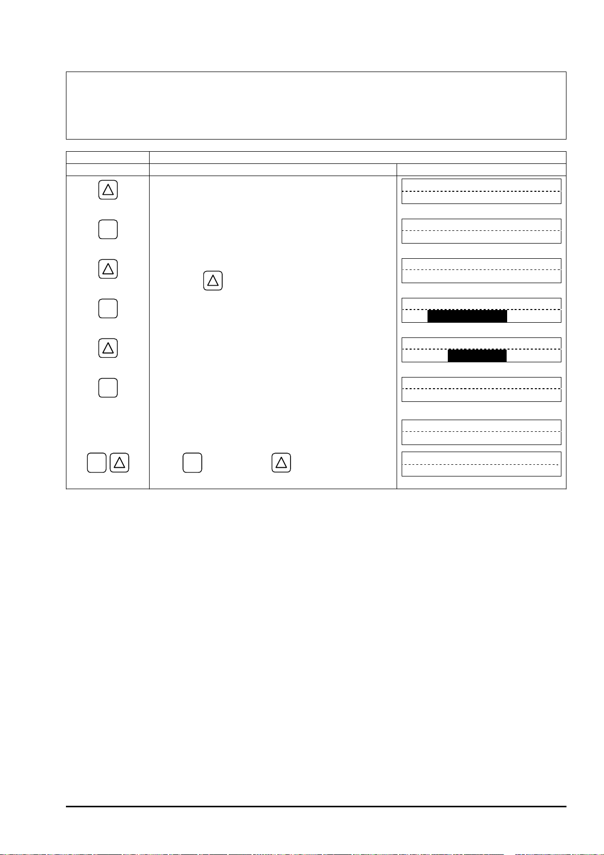
B
ULLETIN F-7
0
4.5.7.1. Invalidating the DO output
Description
Cancels the DO1 OUT and/or DO2 OUT contact output function .
z
For actual keying, refer to the typical operation indicated below. Set the parameter protection to OFF beforehand
(Section 4.4.1).
Typical operation Change the setting of DO1 from "+TOTAL PULSE" to "NOT USED".
Keying order Description Indication
Pressed twice to select the OUTPUT SETUP mode.
ź
OUTPUT SETUP
ESC
ENT
ź
ź
ENT
ź
ź
ENT
ź
ź
ź
ź
Pressed to indicate ZERO ADJUST.
Pressed 5 times to indicate "DO1 OUT".
* Pressing
Pressed to blink the cursor.
Pressed 6 times to indicate "NOT USED" on 2nd line.
Pressed to register "NOT USED".
Press
ESC
the measurement mode.
key again will select "DO2".
--- "NOT USED" registered.---
key once, and
key 3 times to resume
ZERO ADJUST
CLEAR
DO1 OUT
+TOTAL PULSE
DO1 OUT
+TOTAL PULSE
DO1 OUT
NOT USED
DO1 OUT
½½
COMPLETE
Ļ
DO1 OUT
NOT USED
0.000 m/s
0.000 m3/h
½½
-65-
Page 76

B
ULLETIN F-70
4.5.7.2. How to validate the total pulse output
Description
Sets the total pulse output for DO1 OUT and/or DO2 OUT function.
z
+TOTAL PULSE: Forward flow rate total pulse output.
–TOTAL PULSE: Reverse flow rate total pulse output.
Note: Referring to Section 4.5.6.1., set the pulse value, pulse width, etc.
For actual keying, refer to the typical operation indicated below. Set the parameter protection to OFF beforehand
(Section 4.4.1).
Typical operation Set the DO1 output to "+TOTAL PULSE", and the contact to Normally OFF.
Keying order Description Indication
Pressed twice to select the OUTPUT SETUP mode.
ź
OUTPUT SETUP
ENT
ź
ź
ENT
ź
ź
ENT
ź
ź
ź
ź
ENT
ź
ENT
ź
ź
ź
ź
Pressed to indicate ZERO ADJUST.
Pressed 5 times to indicate "DO1 OUT".
* Pressing
key again will select "DO2".
Pressed to blink the cursor.
Pressed to indicate "+TOTAL PULSE" on 2nd line. Or,
to select "–TOTAL PULSE", press
key again.
Pressed to register "+TOTAL PULSE".
--- “+TOTAL PULSE” registered.---
Pressed to indicate "CONTACT ACTION".
Pressed to register "ACTIVE ON" (normally OFF).
* If it is desired to select Normally ON, press
key.
--- "ACTIVE ON" registered.---
ZERO ADJUST
CLEAR
DO1 OUT
NOT USED
DO1 OUT
NOT USED
DO1 OUT
+TOTAL PULSE
DO1 OUT
½½
COMPLETE
Ļ
STATUS OUT
CONTACT ACTION
CONTACT ACTION
ACTIVE ON
CONTACT ACTION
½½
COMPLETE
Ļ
STATUS OUT
CONTACT ACTION
½½
½½
ESC
- 66 -
Press
ESC
the measurement mode.
key twice, and
key 3 times to resume
0.000 m/s
0.000 m3/h
Page 77

B
ULLETIN F-7
0
4.5.7.3. How to validate outputting the FLOW SPAN-2
Description
Select a contact output as DO1 and/or DO2 at FLOW SPAN-2 measurement status.
z
For actual keying, refer to the typical operation indicated below. Set the parameter protection to OFF beforehand
(Section 4.4.1).
Typical operation Set the DO1 output to "FLOW SPAN-2". Also set the contact to Normally OFF.
Keying order Description Indication
Pressed twice to select the OUTPUT SETUP mode.
ź
OUTPUT SETUP
ENT
ź
ź
ENT
ź
ź
ENT
ź
ź
ź
ź
ENT
ź
ENT
ź
ź
ź
ź
Pressed to indicate ZERO ADJUST.
Pressed 5 times to indicate "DO1 OUT".
* Pressing
key again will select "DO2".
Pressed to blink the cursor.
Pressed 3 times to indicate "FLOW SPAN-2" on 2nd line.
Pressed to register "FLOW SPAN-2".
--- "FLOW SPAN-2" registered.---
Pressed to indicate "CONTACT ACTION".
Pressed to register "ACTIVE ON" (normally OFF).
* If it is desired to select Normally ON, press
key.
--- "ACTIVE ON" registered.---
ZERO ADJUST
CLEAR
DO1 OUT
NOT USED
DO1 OUT
NOT USED
DO1 OUT
FLOW SPAN-2
DO1 OUT
½½
COMPLETE
Ļ
STATUS OUT
CONTACT ACTION
CONTACT ACTION
ACTIVE ON
CONTACT ACTION
½½
COMPLETE
Ļ
STATUS OUT
CONTACT ACTION
½½
½½
ESC
Press
ESC
key twice, and
key 3 times to resume
0.000 m/s
0.000 m3/h
the measurement mode.
-67-
Page 78

B
ULLETIN F-70
4.5.7.4. How to validate the alarm output
Description
Select a contact output as DO1 and/or DO2 when received wave or EEPROM is abnormal.
z
Settable range
ALL : Select a contact output when EEPROM and received wave (none or unstable) are
abnormal.
HARDWARE FAULT : Select a contact output when EEPROM is abnormal.
PROCESS ERROR : Select a contact output when received wave is abnormal.
For actual keying, refer to the typical operation indicated below. Set the parameter protection to OFF beforehand
(Section 4.4.1).
Typical operation Set the DO1 output to "PROCESS ERROR". Also set the contact to Normally OFF.
Keying order Description Indication
Pressed twice to select the OUTPUT SETUP mode.
ź
OUTPUT SETUP
ENT
ź
ź
ENT
ź
ź
ENT
ź
ź
ENT
ź
ź
ź
ź
Pressed to indicate ZERO ADJUST.
Pressed 5 times to indicate "DO1 OUT".
* Pressing
key again will select "DO2".
Pressed to blink the cursor.
Pressed 4 times to indicate "ALARM" on 2nd line.
Pressed to indicate the ALARM selection screen.
Pressed twice to indicate "PROCESS ERROR".
Pressed to register it.
--- "PROCESS ERROR" registered.---
ZERO ADJUST
CLEAR
DO1 OUT
NOT USED
DO1 OUT
NOT USED
DO1 OUT
ALARM
ALARM
ALL
ALARM
PROCESS ERROR
ALARM
½½
COMPLETE
Ļ
STATUS OUT
CONTACT ACTION
½½
ESC
- 68 -
ENT
ź
ENT
ź
ź
ź
ź
Press
Pressed to indicate "CONTACT ACTION".
Pressed to register "ACTIVE ON" (normally OFF).
* If it is desired to select Normally ON, press
key.
--- "ACTIVE ON" registered.---
ESC
key twice, and
key 3 times to resume
the measurement mode.
CONTACT ACTION
ACTIVE ON
CONTACT ACTION
½½
COMPLETE
Ļ
STATUS OUT
CONTACT ACTION
0.000 m/s
0.000 m3/h
½½
Page 79

4.5.7.5. How to validate the flow switch
B
0
Description
Select a contact output as DO1 and/or DO2 when the flow rate has exceeded a set value.
z
ULLETIN F-7
Flow rate For UPPER SWITCH
Settable ranges
z
Hysteresis
Time
ON or OFF
Flow rate For LOWER SWITCH
Hysteresis
Time
ON or OFF
Flow rate : 0 to 10 m/s in terms of flow velocity.
Action : UPPER SWITCH or LOWER SWITCH.
Contact action : ACTIVE ON ... DO1 normally OFF, DO2 normally open.
ACTIVE OFF ... DO1 normally ON, DO2 normally closed.
Note: The hysteresis value set in Section 4.5.5 "Setting the flow rate and flow velocity range” is applied to the
switch action range.
actual keying, refer to the typical operation indicated below. Set the parameter protection to OFF beforehand
For
(Section 4.4.1).
3
Typical operation Set the DO1 output to "UPPER SWITCH", and upper limit flow rate to 12 [m
/h]. Also, set the
contact to Normally OFF.
Keying order Description Indication
Pressed twice to select the "OUTPUT SETUP" mode.
OUTPUT SETUP
ź
ENT
ź
ź
ENT
ź
ź
ENT
ź
ENT
ź
ź
Pressed to indicate "ZERO ADJUST".
Pressed 5 times to indicate "DO1 OUT".
* Pressing
key again will select "DO2".
Pressed to blink the cursor.
Pressed 5 times to select "FLOW SWITCH" on 2nd line.
Pressed to indicate the flow rate setting screen for the
"UPPER SWITCH".
* Pressing
key will select the flow rate setting
screen for the "LOWER SWITCH".
Pressed to blink the cursor.
Pressed 3 times to move the cursor.
ZERO ADJUST
CLEAR
DO1 OUT
NOT USED
DO1 OUT
NOT USED
DO1 OUT
FLOW SWITCH
UPPER SWITCH
10.0000 m3/h
UPPER SWITCH
0010.0000 m3/h
UPPER SWITCH
0010.0000 m3/h
-69-
Page 80
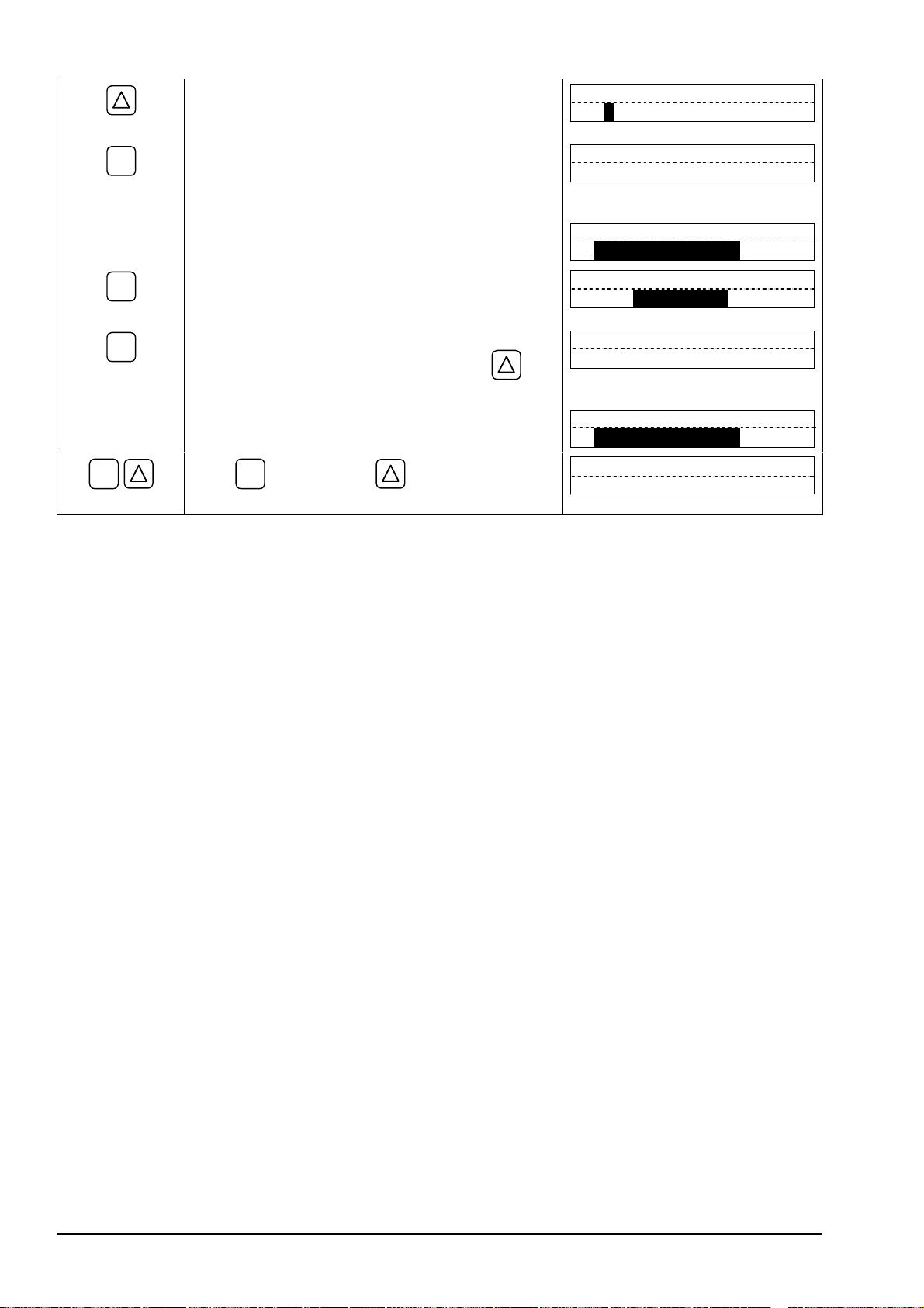
B
ULLETIN F-70
ESC
ź
ENT
ź
ź
ź
ź
ENT
ź
ENT
ź
ź
ź
ź
Press
Pressed twice to select "2".
Pressed to register it.
--- "UPPER SWITCH" registered.---
Pressed to indicate "CONTACT ACTION".
Pressed to register "ACTIVE ON" (normally OFF).
* If it is desired to select Normally ON, press
key.
--- "ACTIVE ON" registered.---
ESC
key twice, and
key 3 times to resume
the measurement mode.
UPPER SWITCH
0012.0000 m3/h
UPPER SWITCH
½½
COMPLETE
Ļ
STATUS OUT
CONTACT ACTION
CONTACT ACTION
ACTIVE ON
CONTACT ACTION
½½
COMPLETE
Ļ
STATUS OUT
CONTACT ACTION
0.000 m/s
0.000 m3/h
½½
½½
- 70 -
Page 81

4.5.7.6. How to validate the total switch
B
0
ULLETIN F-7
Description
Select a contact output as DO1 and/or DO2 when the total value
z
Total value
exceeds a set value.
Settable range: 0.000001 to 99999999
Contact action:
ACTIVE ON ..... DO1 normally OFF, DO2 normally open.
Setting
value
ACTIVE OFF ... DO1 normally ON, DO2 normally closed.
Note: Different values can be assigned to DO1 and DO2.
actual keying, refer to the typical operation indicated below.
For
Time
Set the parameter protection to OFF beforehand (Section 4.4.1).
ON or OFF
Typical operation Set the DO1 output to “TOTAL SWITCH”, and change the setting from 10000 [m3] to 100 [m3].
Also, set the contact to Normally OFF.
Keying order Description Indication
Pressed twice to select the OUTPUT SETUP mode.
OUTPUT SETUP
ź
ENT
Pressed to indicate ZERO ADJUST.
ZERO ADJUST
CLEAR
ź
ź
Pressed 5 times to indicate "DO1 OUT".
* Pressing
key again will select "DO2".
DO1 OUT
NOT USED
ENT
ź
ź
ENT
ź
ENT
ź
ź
ź
ź
ź
Pressed to blink the cursor.
Pressed 6 times to select "TOTAL SWITCH" on 2nd line.
Pressed to indicate the setting screen for "TOTAL
SWITCH".
Pressed to blink the cursor.
Pressed 3 times to move the cursor.
Pressed 10 times to select "0".
Pressed twice to move the cursor
Pressed to select "1".
DO1 OUT
NOT USED
DO1 OUT
TOTAL SWITCH
TOTAL SWITCH
10000 m3
TOTAL SWITCH
00010000 m3
TOTAL SWITCH
00010000 m3
TOTAL SWITCH
00000000 m3
TOTAL SWITCH
00000000 m3
TOTAL SWITCH
00000100 m3
ENT
ź
Pressed to register it.
TOTAL SWITCH
½½
COMPLETE
½½
Ļ
ź
ź
ź
--- "TOTAL SWITCH" registered.---
STATUS OUT
CONTACT ACTION
-71-
Page 82

B
ULLETIN F-70
ESC
ENT
ź
ENT
ź
ź
ź
ź
Press
Pressed to indicate "CONTACT ACTION".
Pressed to register "ACTIVE ON" (normally OFF).
* If it is desired to select Normally ON, press
key.
--- "ACTIVE ON" registered.---
ESC
key twice, and
key 3 times to resume
the measurement mode.
CONTACT ACTION
ACTIVE ON
CONTACT ACTION
½½
COMPLETE
Ļ
STATUS OUT
CONTACT ACTION
0.000 m/s
0.000 m3/h
½½
- 72 -
Page 83

4.5.8. How to compensate the measurement value
B
0
ULLETIN F-7
Description
Used for compensating the measurement value.
z
The span can be compensated
by a preset reading percentage.
Compensatable range: ±200%
Output
100%
The output value (reading, analog output and total output) is
computed by the following expression.
measurement value u [compensation value %]
Output =
actual keying, refer to the typical operation indicated below. Set the parameter protection to OFF beforehand
For
100
(Section 4.4.1).
Typical operation Compensate the measurement value by 1 %.
Keying order Description Indication
Pressed twice to select the OUTPUT SETUP mode.
OUTPUT SETUP
ź
ENT
Pressed to indicate ZERO ADJUST.
ZERO ADJUST
CLEAR
ź
Pressed 7 times to indicate "CALIBRATION SPAN".
CALIBRATION SPAN
100.0 %
ź
Flow rate
ESC
ENT
ź
ź
ź
ENT
ź
ź
ź
ź
Press
Pressed to blink the cursor.
Pressed twice to move the cursor.
Pressed to select "1".
Pressed to register it.
--- Compensation value registered.---
ESC
key once, and
the measurement mode.
key 3 times to resume
CALIBRATION SPAN
100.0 %
CALIBRATION SPAN
100.0 %
CALIBRATION SPAN
101.0 %
CALIBRATION SPAN
½½
COMPLETE
Ļ
CALIBRATION SPAN
101.0 %
0.000 m/s
0.000 m3/h
½½
-73-
Page 84

B
ULLETIN F-70
4.6. Measure setup mode
4.6.1. How to set the unit system
Description
Select a measurement unit system.
z
Metric system (factory set)
z
Length································ mm
Flow velocity ····················· m/s
Flow rate···························· L/s, L/min, L/h, ML/d, m
Inch system
z
MBBL/d
Total··································· mL, L, m
3
, km3, Mm3, mBBL, BBL, kBBL
Length································ inch
Flow velocity ····················· ft/s
Flow rate···························· gal/s, gal/min, gal/h, Mgal/d, ft
MBBL/d
Total··································· gal, kgal, ft
3
, kft3, Mft3, mBBL, BBL, kBBL, ACRE-in, ACRE-ft
For actual keying, refer to the typical operation indicated below. Set the parameter protection to OFF beforehand
(Section 4.4.1).
3
/s, m3/min, m3/h, Mm3/d, BBL/s, BBL/min, BBL/h,
3
/s, ft3/min, ft3/h, Mft3/d, BBL/s, BBL/min, BBL/h,
Typical operation Change the unit system from inch system to metric system.
Keying order Description Indication
Pressed 3 times to indicate "MEASURE SETUP".
MEASURE SETUP
ź
ENT
Pressed to indicate "SYSTEM UNIT".
SYSTEM UNIT
ENGLISH
ź
ENT
Pressed to blink the cursor.
SYSTEM UNIT
ENGLISH
ź
Pressed to indicate "METRIC".
SYSTEM UNIT
METRIC
ź
ENT
Pressed to register it.
SYSTEM UNIT
½½
COMPLETE
ź
ź
ESC
ź
ź
Press
--- "METRIC" registered.---
ESC
key once, and
key twice to resume
SYSTEM UNIT
METRIC
0.000 m/s
0.000 m3/h
the measurement mode.
½½
Ļ
- 74 -
Page 85

B
ULLETIN F-7
0
4.6.2. How to set the flow rate unit
Description
Select the unit of flow rate.
z
Metric system
z
Flow rate···················· L/s (factory set), L/min, L/h, ML/d, m
BBL/h, MBBL/d
Inch system
z
Flow rate···················· gal/s, gal/min, gal/h, Mgal/d, ft
MBBL/d
<Caution> First, set the unit system (metric or inch) according to Section 4.6.1.
For actual keying, refer to the typical operation indicated below. Set the parameter protection to OFF beforehand
(Section 4.4.1).
Typical operation Set the flow rate unit to [m3/h].
Keying order Description Indication
Pressed 3 times to indicate "MEASURE SETUP".
ź
3
/s, m3/min, m3/h, Mm3/d, BBL/s, BBL/min,
3
/s, ft3/min, ft3/h, Mft3/d, BBL/s, BBL/min, BBL/h,
MEASURE SETUP
ESC
ENT
ź
ź
ENT
ź
ź
ENT
ź
ź
ź
ź
Pressed to indicate "SYSTEM UNIT".
Pressed to indicate "FLOW UNIT".
Pressed to blink.
Pressed 6 times to select "m
Pressed to register it.
3
--- "m
/h" registered.---
Press
ESC
key once, and
the measurement mode.
3
/h".
key twice to resume
SYSTEM UNIT
METRIC
FLOW UNIT
L/S
FLOW UNIT
L/S
FLOW UNIT
m3/h
FLOW UNIT
½½
COMPLETE
Ļ
FLOW UNIT
m3/h
0.000 m/s
0.000 m3/h
½½
-75-
Page 86
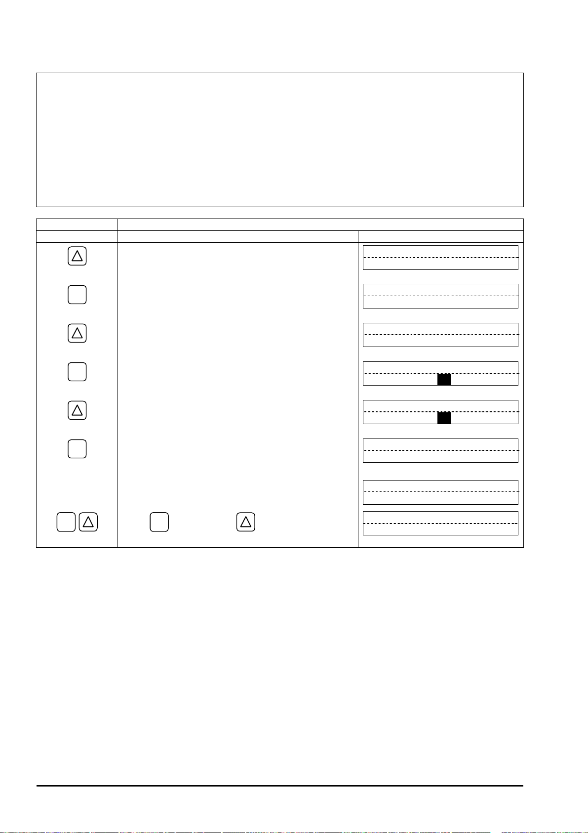
B
ULLETIN F-70
4.6.3. How to set the total unit
Description
Select the totalizer unit of volume.
z
Metric system
z
Total··························· mL (factory set), L, m
Inch system
z
Total··························· gal, kgal, ft
3
, kft3, Mft3, mBBL, BBL, kBBL, ACRE-in, ACRE-ft
<Caution> First, set the unit system (metric or inch) according to Section 4.6.1.
For actual keying, refer to the typical operation indicated below. Set the parameter protection to OFF beforehand
(Section 4.4.1).
Typical operation Set the total unit to [m3].
Keying order Description Indication
Pressed 3 times to indicate "MEASURE SETUP".
ź
3
, km3, Mm3, mBBL, BBL, kBBL
MEASURE SETUP
ESC
ENT
ź
ź
ENT
ź
ź
ENT
ź
ź
ź
ź
Press
Pressed to indicate "SYSTEM UNIT".
Pressed twice to indicate "TOTAL UNIT".
Pressed to blink.
3
Pressed twice to select "m
".
Pressed to register it.
3
--- "m
" registered.---
ESC
key once, and
key twice to resume
the measurement mode.
SYSTEM UNIT
METRIC
TOTAL UNIT
mL
TOTAL UNIT
mL
TOTAL UNIT
m3
TOTAL UNIT
½½
COMPLETE
Ļ
TOTAL UNIT
m3
0.00 m3/h
+ 0.00 m3
½½
- 76 -
Page 87

B
ULLETIN F-7
0
4.6.4. How to set the piping parameters
Description
Set the parameters of piping and fluid to be measured to determine the sensor unit spacing.
z
Set the following parameters, calculate the sensor unit spacing value and then, to match the result, install the
sensor units into the frame.
Unless the sensor units are spaced accurately, the measurement may demonstrate excessive error.
z
The received signal waveform may be abnormal as a result of incorrect piping or fluid parameters.
z
Setting item
1. Pipe outer diameter : 10 to 650 [mm] (factory set at 60.00 [mm]).
2. Pipe material : PVC (factory set), PVDF, PEEK, PP, CARBON STEEL, STAINLESS STEEL,
COPPER, others (sound velocity 1000 to 3700 m/s).
3. Wall thickness : 0.1 to 50.00 [mm] (factory set at 4.50 [mm]).
4. Lining material : NO LINING (factory set), TAR EPOXY, MORTAL, RUBBER, TEFLON,
PYREXGLASS, others (sound velocity: 1000 to 3700 [m/s]).
5. Lining material thickness : 0.01 to 50.00 [mm].
6. Fluid to be measured : WATER, SEA WATER, others (sound velocity: 500 to 2500 [m/s])
7. Kinematic viscosity : 0.0001 to 999.9999u10
8. Detector mounting method : V method (factory set), Z method
9. Detector type : SX3A (factory set), SX3B, SX3C, SX3D
-6
[m2/s] (factory set at 1.0038u10-6 [m2/s])
For actual keying, refer to the typical operation indicated below. Set the parameter protection to OFF beforehand
(Section 4.4.1)
Typical operation Carry out setting for measuring the flow rate of water flowing through PVC pipe (for tap water)
having 100 mm of nominal diameter.
Keying order Description Indication
ź
ENT
ź
ź
ENT
ź
ENT
ź
ź
Pressed 3 times to indicate "MEASURE SETUP".
Pressed to indicate "SYSTEM UNIT".
Pressed 3 times to indicate "PIPE PARAMETER".
Pressed to indicate "OUTER DIAMETER".
Pressed to blink the cursor.
Operated to compose "114" because, from piping data in
Section 6.6., the outer diameter of polyvinyl chloride pipe
(tap water size) is 114 mm.
MEASURE SETUP
SYSTEM UNIT
METRIC
PIPE PARAMETER
S= 16 ( 48mm)
OUTER DIAMETER
60.00 mm
OUTER DIAMETER
060.00 mm
OUTER DIAMETER
114.00 mm
ENT
ź
ź
ź
ź
Pressed to register the outer diameter.
--- “OUTER DIAMETER” registered.---
OUTER DIAMETER
½½
COMPLETE
Ļ
OUTER DIAMETER
114.00 mm
½½
-77-
Page 88

B
ULLETIN F-70
ź
ź
ENT
ź
ź
ENT
ź
ź
ź
ź
ź
Pressed to indicate "PIPE MATERIAL". Because PVC
(factory set) is already registered, go to the next step.
Note: If the pipe is made of another material, press
ENT
key, and select a corresponding menu.
Pressed to indicate "WALL THICKNESS".
Pressed to blink the cursor.
Operated to compose "7.0" because, from piping data in
Section 6.6., the wall thickness of polyvinyl chloride pipe
(tap water size) is 7.0 mm.
Pressed to register the wall thickness.
--- “WALL THICKNESS” registered.---
Pressed to indicate "LINING MATERIAL".
"NO LINING" (factory set) is already registered.
Because there is no lining, go to the next step.
ENT
Note: If lining is provided, press
key, and select a
corresponding menu. Or, input a sound velocity.
Next, go to "LINING THICKNESS", and input a
lining thickness. Nothing is indicated in case of
"NO LINING".
PIPE MATERIAL
PVC
WALL THICKNESS
4.50 mm
WALL THICKNESS
004.50 mm
WALL THICKNESS
007.00 mm
WALL THICKNESS
½½
COMPLETE
Ļ
WALL THICKNESS
7.00 mm
LINING MATERIAL
NO LINING
½½
ESC
ź
ź
ESC
ź
Press
Pressed to indicate "KIND OF FLUID". Because
"WATER" (factory set) is already registered, go to the
next step.
Note: If fluid to be measured is other than water, press
ENT
key, and input the sea water or measurement
fluid's sound velocity.
Pressed to indicate "KINEMATIC VISCO". Input the
kinematic viscosity of the fluid to be measured. Because
the kinematic viscosity 1.0038E–6 [m
2
/s] of water at 20qC
is already registered, go to the next step. In case of fluid
other than water, input the kinematic viscosity at a
measurement status of fluid to be measurued referring to
data in Section 6.6., etc.
Pressed to indicate "PIPE PARAMETER". "S= 31" is
indicated on 2nd line. After mounting the frames on
piping, insert into it 2 sensor units spaced at 31 divisions.
ESC
key once, and
key twice to resume
the measurement mode.
KIND OF FLUID
WATER
KINEMATIC VISCO
1.0038 E–6m2/s
PIPE PARAMETER
S= 31 ( 93mm)
0.00 m3/h
+ 0.00 m3
- 78 -
Page 89

B
ULLETIN F-7
0
4.7. Maintenance mode
4.7.1. How to calibrate the analog output
Description
The calibration is performed to output 4 mA and 20 mA when the analog signal (4-20 mA DC) output is 0%
z
and 100%, respectively.
Connect an ammeter to Iout terminals as shown below. In the CURRENT CALIBRATION mode, select 4 mA or
z
20 mA, and operate
key (UP) or key (Down).
Ammeter
+
-
For
actual keying, refer to the typical operation indicated below. Set the parameter protection to OFF beforehand
Iout
DO1+DO2
+
+
-
Iout-DO1-DO2
(Section 4.4.1).
Typical operation Calibrate the output of 4 mA and 20 mA.
Keying order Description Indication
Pressed 4 times to indicate "MAINTENANCE MODE".
MAINTENANCE MODE
ź
ENT
Pressed to indicate "CURRENT CALIBRATION".
CURRENT
CALIBRATION
ź
ENT
ź
Pressed twice to select the calibration mode for 4 mA.
(When the cursor blinks, 4 mA of current is outputted.)
Then, press
(UP) or (Down) key so as to
CURRENT
4 mA
obtain 4 mA, watching the reading on ammeter or other
calibration instruments.
ESC
ENT
ź
ź
ź
ź
ź
ENT
ź
ENT
ź
ź
ź
ź
Pressed to register the calibration result.
--- 4 mA calibration registered.---
Pressed to select 20 mA.
Pressed to select the calibration mode for 20 mA.
(When the cursor blinks, 20 mA of current is outputted.)
Then, press
(UP) or (Down) key so as to
obtain 20 mA.
Pressed to register the calibration result.
--- 20 mA calibration registered.---
Press
ESC
key twice, and
key once to resume
the measurement mode.
CURRENT
½½
COMPLETE
Ļ
CURRENT
4 mA
CURRENT
20 mA
CURRENT
20 mA
CURRENT
½½
COMPLETE
Ļ
CURRENT
20 mA
0.000 m/s
0.000 m3/h
½½
½½
-79-
Page 90

B
ULLETIN F-70
4.7.2. How to set the constant current output
Description
Generates a fixed value output of analog signal.
z
Application example: The operation of a connected ammeter is checked by generating a fixed value output of analog
signal.
In the constant current setting mode (CURRENT OUTPUT SETTING), set the constant current output value.
z
Settable range: -20% (0.8 mA) to +120% (23.2 mA).
For actual keying, refer to the typical operation indicated below. Set the parameter protection to OFF beforehand
(Section 4.4.1).
Typical operation Set the constant current output of 50% (12 mA).
Keying order Description Indication
Pressed 4 times to indicate "MAINTENANCE MODE".
ź
MAINTENANCE MODE
ENT
ź
ź
ENT
ź
ENT
ź
ź
ENT
ź
ź
ź
ź
ESC
ź
Pressed to indicate "CURRENT CALIBRATION".
Pressed to indicate "CURRENT OUTPUT SETTING".
Pressed to select the setting screen.
Pressed to blink the cursor.
Note: A constant current output starts.
Operated to compose [12].
Pressed to output 12 mA.
--- 12 mA is being outputted.---
Pressed to stop the constant current output.
Note: The current output at a measurement status is
resumed.
CURRENT
CALIBRATION
CURRENT
OUTPUT SETTING
CURRENT SETTING
4.0 mA
CURRENT SETTING
04.0 mA
CURRENT SETTING
12.0 mA
CURRENT SETTING
½½
COMPLETE
Ļ
CURRENT SETTING
12.0 mA
CURRENT
OUTPUT SETTING
½½
ESC
- 80 -
Press
ESC
measurement mode.
key and
key to resume the
0.000 m/s
0.000 m3/h
Page 91

B
ULLETIN F-7
0
4.7.3. How to check the action of total pulses
Description
Checks the action of total pulse output.
z
The output action can be verified upon setting the number of pulses to be outputted per second.
Settable range: 1 to 100 pulses/s. (DO1 only)
Note: 1. The output pulse width is as currently set (see Section 4.5.6.1.)
Set the frequency taking the pulse width into account referring to the following expression.
Pulse count setting 1000/(pulse width [ms] u2)
Example: If the pulse width is set at 50 ms, select 10 pulses/s or less.
Note: 2. DO1 (transistor open collector) and DO2 (relay contact) operate simultaneously.
Before checking the action, confirm whether proceeding to an action is all right or not.
Note: 3. DO2 (relay contact) always operates at the rate of 1 pulse/sec.
For actual keying, refer to the typical operation indicated below. Set the parameter protection to OFF beforehand
(Section 4.4.1).
Typical operation Output 5 pulses/s.
Keying order Description Indication
Pressed 4 times to indicate "MAINTENANCE MODE".
ź
MAINTENANCE MODE
ENT
ź
ź
ENT
ź
ź
ź
ENT
ź
ź
ź
ź
ESC
ź
Pressed to indicate "CURRENT CALIBRATION".
Pressed twice to indicate "TOTAL PULSE".
Pressed to blink the cursor.
Note: Outputting simulated pulses starts.
Pressed twice to move the cursor.
Pressed 4 times to select "5".
Pressed to register it.
--- 5 pulses/s registered.---
5 simulated pulses/s are outputted.
Pressed to stop the simulated output after the end of
checking the output.
CURRENT
CALIBRATION
TOTAL PULSE
1 PULSE/s
TOTAL PULSE
001 PULSE/s
TOTAL PULSE
001 PULSE/s
TOTAL PULSE
005 PULSE/s
TOTAL PULSE
½½
COMPLETE
Ļ
TOTAL PULSE
005 PULSE/s
TOTAL PULSE
005 PULSE/s
½½
ESC
Press
ESC
measurement mode.
key once, and
key once to resume the
0.000 m/s
0.000 m3/h
-81-
Page 92
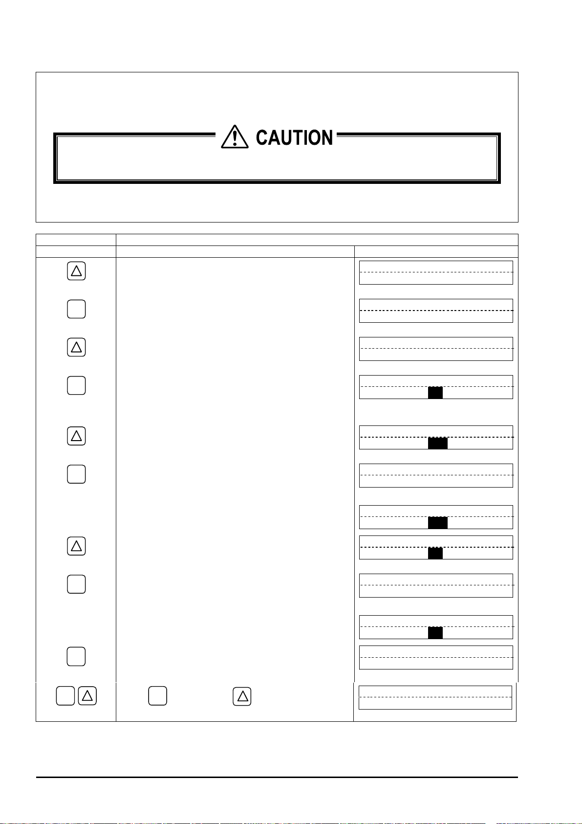
B
ULLETIN F-70
4.7.4. How to check the status output
Description
Check the status output.
z
Settable range: ON ... Short-circuits the contact. OFF ... Open-circuits the contact.
This operation sets DO1 and DO2 with the same contact action.
z
Before operation, check whether process conditions permit changing the DO output.
z
For concrete keying, refer to the typical operation indicated below. Set the parameter protection to OFF beforehand
(Section 4.4.1)
Typical operation Check the contact action.
Keying order Description Indication
Pressed 4 times to indicate "MAINTENANCE MODE".
ź
MAINTENANCE MODE
ENT
ź
ź
ENT
ź
ź
ENT
ź
ź
ź
ź
ź
ENT
ź
ź
ź
ź
Pressed to indicate "CURRENT CALIBRATION".
Pressed 3 times to indicate "STATUS OUTPUT".
Pressed to blink the cursor.
Note: At this time, the contact output is set as indicated.
In the example shown on the right, the contact
output is set as “ON”.
Pressed to select "OFF".
Pressed to register "OFF".
--- "OFF" registered.---
* Make sure the contact output is "OFF".
Pressed to select "ON".
Pressed to register "ON".
--- "ON" registered.---
* Make sure the contact output is "ON".
CURRENT
CALIBRATION
STATUS OUTPUT
ON
STATUS OUTPUT
ON
STATUS OUTPUT
OFF
STATUS OUTPUT
½½
COMPLETE
Ļ
STATUS OUTPUT
OFF
STATUS OUTPUT
ON
STATUS OUTPUT
½½
COMPLETE
Ļ
STATUS OUTPUT
ON
½½
½½
ESC
- 82 -
ESC
ź
Press
Pressed once to stop the blinking of the cursor.
* At this time, the contact output is set at normal
measurement status.
ESC
key once, and
measurement mode.
key once to resume the
STATUS OUTPUT
ON
0.000 m/s
0.000 m3/h
Page 93

B
ULLETIN F-7
0
4.7.5. How to validate the test mode (simulated flow rate output)
Description
Checks different outputs (LCD indication, analog output, DO
z
output) upon simulating flow rate outputs. With the initial output
starting at some value, the output will be changed to the new value
which is the new simulated flow rate output. The tracking time sets
the time for which the new value becomes constant - mathcing the
simulated flow rate output that is programmed. So long as the
test mode is activated, "T" blinks on the left end of the 1st line of LCD
on the measurement mode screen.
Settable contents
Test mode validation : Activates or cancels the test mode.
Input value : Simulated flow rate target value.
Tracking time : Time required to attain the simulated flow rate target value.
Settable ranges
Test mode validation : SETTING (valid), NOT USED (invalid).
Input value : 0 to ±10 [m/s] in terms of flow velocity.
Tracking time : 0 to 999 seconds.
In this mode, the analog output, and DO1 and DO2 outputs are changed. Ensure process measurement
z
conditions permit changes to these outputs.
Be sure to resume "NOT USED" setting after tesing. Otherwise, the input value output status will be
z
held until power is turned off.
If the TOTAL MODE is set at "START", the total value also changes. If total must be maintained during
z
testing with simulating flow rate, set TOTAL MODE to "STOP" in advance.
Flow rate output
Input value
Initial value
Tracking time
Time
For actual keying, refer to the typical operation indicated below. Set the parameter protection to OFF beforehand
(Section 4.4.1).
Typical operation Set the simulated flow rate target to 10 [m3/h], and the tracking time to 100 [s].
Keying order Description Indication
Pressed 4 times to indicate "MAINTENANCE MODE".
MAINTENANCE MODE
ź
ENT
Pressed to indicate "CURRENT CALIBRATION".
CURRENT
CALIBRATION
ź
Pressed 4 times to indicate "TEST MODE".
TEST MODE
NOT USED
ź
ENT
Pressed to blink the cursor.
TEST MODE
NOT USED
ź
Pressed to select "SETTING".
TEST MODE
SETTING
ź
ENT
Pressed to register "SETTING".
INPUT DATA
0 m3/h
ź
ENT
Pressed to blink the cursor on 2nd line.
INPUT DATA
000000000 m3/h
ź
-83-
Page 94

B
ULLETIN F-70
ź
ENT
ź
ź
ź
ź
ź
ENT
ź
ź
ENT
ź
ź
ź
ź
Using
key and key, compose "10".
Pressed to register it.
--- Simulated flow rate target registered.---
Pressed to indicate "TRACKING TIME".
Pressed to blink the cursor on 2nd line.
Pressed to select "100".
Pressed to register it.
--- "TRACKING TIME" registered.---
* At this time, the simulated output action starts.
INPUT DATA
000000010 M3/h
INPUT DATA
½½
COMPLETE
Ļ
INPUT DATA
10 m3/h
TRACKING TIME
0 s
TRACKING TIME
000 s
TRACKING TIME
100 s
TRACKING TIME
½½
COMPLETE
Ļ
TRACKING TIME
100 s
½½
½½
ESC
Press
ESC
key and
key to resume the
measurement mode. "T" blinks on the left end of 1st
line of LCD, and the output changes. In 100 seconds (at
which tracking time is set), the output becomes stable at
3
10 [m
/h] (simulated flow rate target).
Note: Be sure to return the TEST MODE to "NOT
USED" after checking the output.
T 0.068 m/s
0.500 m3/h
Ļ
T 1.359 m/s
10.000 m3/h
- 84 -
Page 95

B
ULLETIN F-7
0
4.7.6. How to validate a serial transmission (RS-232C/RS-485)
Description
Check the serial communication before use.
z
Settable contents
Transmission type, transmission rate, parity, stop bits and slave No.
Settable ranges
Transmission type : RS-232C (factory set) or RS-485.
Transmission rate (baud rate) : 2400 BPS, 4800 BPS, 9600 BPS (factory set), 19200 BPS.
Parity : NON (factory set), ODD, EVEN.
Stop bits : 1 BIT (factory set), 2 BITS.
Slave No. : 0 (factory set) to 63.
Note: For the transmission specifications, refer to "External communication specifications" in Section 6.1.
For actual keying, refer to the typical operation indicated below. Set the parameter protection to OFF beforehand
(Section 4.4.1).
Typical operation Select the RS-485, and set the baud rate to 9600 BPS, the parity to "ODD", the stop bits to "1 BIT",
and the slave No. to "5".
Keying order Description Indication
Pressed 4 times to indicate "MAINTENANCE MODE".
MAINTENANCE MODE
ź
ENT
ź
ź
ENT
ź
ź
ENT
ź
ź
ź
ź
ź
Pressed to indicate "CURRENT CALIBRATION".
Pressed 5 times to indicate "COMMUNICATION".
Pressed to select, and pressed again to blink the 2nd line.
Pressed to indicate "RS-485".
Pressed to register it.
--- RS-485 registered.---
Pressed to indicate "COM. BAUD RATE". Because
"9600 BPS" is already selected, go to the next step. If it
ENT
is desired to select another baud rate, press
key,
CURRENT
CALIBRATION
COMMUNICATION
COM. MODE
RS-232C
COM. MODE
RS-485
COM. MODE
½½
COMPLETE
Ļ
COM. MODE
RS-485
COM. BAUD RATE
9600 BPS
½½
ENT
key
COM. PARITY
NON
COM. PARITY
NON
COM. PARITY
ODD
ź
ENT
ź
ź
operate
to register.
Pressed to indicate "COM. PARITY".
Pressed to blink the 2nd line.
Pressed to indicate "ODD".
key for selecting it, and press
-85-
Page 96

B
ULLETIN F-70
ENT
ź
ź
ź
ź
ź
ź
ENT
ź
ź
ENT
ź
ź
ź
ź
Pressed to register it.
--- ODD registered.---
Pressed to indicate "COM. STOP BIT". Because "1
BIT" is already selected, go to the next step. If it is
ENT
desired to select "2 BITS", press
key for selecting it, and press
key, operate
ENT
key to register
it.
Pressed to indicate "COM. SLAVE NO."
Pressed to blink the cursor.
Using
key and key, compose "5".
Pressed to register it.
--- "SLAVE NO." registered.---
COM. PARITY
½½
COMPLETE
Ļ
COM. PARITY
ODD
COM. STOP BIT
1BIT
COM. SLAVE NO.
00
COM. SLAVE NO.
00
COM. SLAVE NO.
05
COM. SLAVE NO.
½½
COMPLETE
Ļ
COM. SLAVE NO.
05
½½
½½
ESC
Press
ESC
measurement mode.
key and
key to resume the
0.000 m/s
0.000 m3/h
- 86 -
Page 97

B
ULLETIN F-7
0
4.7.7. How to validate the synchronization
Description
Transmits ultrasonic waves according to synchronizing signals from the master flow transmitter.
z
Used to avoid the influence by mutual interference between several flow meters located near each other. Used, for
z
example, when they are installed near the same pipe, signal cables pass through the same conduit or there may
otherwise be signal interference or crosstalk.
Reception of synchronizing signal is checked (on slave flow transmitter).
z
Settable contents
MASTER,SLAVE
For actual keying, refer to the typical operation indicated below. Set the parameter protection to OFF beforehand
(Section 4.4.1).
Typical operation Select a SLAVE.
Keying order Description Indication
Pressed 4 times to indicate "MAINTENANCE MODE".
ź
MAINTENANCE MODE
ENT
ź
ź
ENT
ź
ź
ENT
ź
ź
ź
ź
ź
ź
ź
ESC
ź
Pressed to indicate "CURRENT CALIBRATION".
Pressed 6 times to indicate "SYNCHRONIZATION".
Pressed to blink the 2nd line.
Pressed to indicate "SLAVE".
Pressed to register it.
--- SLAVE registered.---
* The reception of synchronizing signal is checked by
the SLAVE, if registered. "NORMAL" appears if the
synchronizing signal has been received, or "ERROR"
if not received properly.
Note: Nothing appears if "MASTER" was registered.
Pressed to indicate "SLAVE".
CURRENT
CALIBRATION
SYNCHRONIZATION
MASTER
SYNCHRONIZATION
MASTER
SYNCHRONIZATION
SLAVE
SYNCHRONIZATION
½½
COMPLETE
Ļ
SLAVE CHECK
NORMAL
SYNCHRONIZATION
SLAVE
½½
ESC
Using
measurement mode.
ESC
key and
key, resume the
0.000 m/s
0.000 m3/h
-87-
Page 98

B
ULLETIN F-70
4.7.8. How to select the language
Description
Can select an indication language (English, Japanese, German, French, Spanish).
z
Settable contents
ENGLISH (factory set), JAPANESE, GERMAN, FRENCH, SPANISH.
For concrete keying, refer to the typical operation indicated below. Set the parameter protection to OFF beforehand
(Section 4.4.1).
Typical operation Select German as an indication language.
Keying order Description Indication
Pressed 4 times to indicate "MAINTENANCE MODE".
ź
MAINTENANCE MODE
ESC
ENT
ź
ź
ENT
ź
ź
ENT
ź
ź
ź
ź
Using
Pressed to indicate "CURRENT CALIBRATION".
Pressed 7 times to indicate "LANGUAGE".
Pressed to blink the 2nd line.
Pressed twice to indicate "GERMAN".
Pressed to register it.
--- “GERMAN” registered.---
key and
ESC
measurement mode.
key, resume the
CURRENT
CALIBRATION
LANGUAGE
ENGLISH
LANGUAGE
ENGLISH
LANGUAGE
GERMAN
LANGUAGE
½½
COMPLETE
Ļ
SPRACHE
DEUTSCH
0.000 m/s
0.000 m3/h
½½
- 88 -
Page 99

B
ULLETIN F-7
0
4.7.9. How to set the ID No.
Description
Set the ID No. for protection of parameters (Section 4.4.1.).
z
If ID No. is set, the number must be inputted before canceling the parameter protection.
To validate the parameter protection, set the parameter protection to "PROTECTION ON" (see Section 4.4.1.).
z
ID No. settable range: 0000 to 9999 (4 digits).
For actual keying, refer to the typical operation indicated below. Set the parameter protection to OFF beforehand
(Section 4.4.1).
Typical operation Set the ID No. to "1106".
Keying order Description Indication
Pressed 4 times to indicate "MAINTENANCE MODE".
ź
MAINTENANCE MODE
ESC
ENT
ź
ź
ENT
ź
ź
ENT
ź
ź
ź
ź
Pressed to indicate "CURRENT CALIBRATION".
Pressed 8 times to indicate "ID NO."
Pressed 2 times to blink the 2nd line.
Press
Pressed to register it.
Using
measurement mode.
Note: To validate the parameter protection, set the
key and key for composing "1106".
--- ID No. registered.---
ESC
key and
parameter protection to "PROTECTION ON".
key, resume the
CURRENT
CALIBRATION
REGISTER ID NO.
REGISTER ID NO.
0000
REGISTER ID NO.
1106
REGISTER ID NO.
½½
COMPLETE
Ļ
REGISTER ID NO.
0.000 m/s
0.000 m3/h
½½½½
½½
-89-
Page 100

B
ULLETIN F-70
4.7.10. How to confirm the software version
Description
Indicates the software version.
z
For actual keying, refer to the typical operation indicated below.
Typical operation Inquire the software version.
Keying order Description Indication
Pressed 4 times to indicate "MAINTENANCE MODE".
ź
MAINTENANCE MODE
ESC
ENT
ź
ź
Using
Pressed to indicate "CURRENT CALIBRATION".
Pressed 9 times to indicate "Ver. No."
key and
ESC
measurement mode.
key, resume the
CURRENT
CALIBRATION
VER. NO
UXF2 00A
0.000 m/s
0.000 m3/h
- 90 -
 Loading...