

Page 1
Series UT Transmitters
Specifications - Installation and Operating Instructions
Bulletin L-UT
DWYER INSTRUMENTS, INC.
P.O. BOX 373 • MICHIGAN CITY, INDIANA 46360, U.S.A. Fax: 219/872-9057 e-mail: info@dwyer-inst.com
Phone: 219/879-8000 www.dwyer-inst.com
Page 2

able of Contents
T
hapter 1. Introducing Series UT
C
ensor Dimensions . . . . . . . . . . . . . . . . . . . . . . . . . . . . . . . . . . . . . . . . . . . . . . . .2
S
Series UTC Specifications . . . . . . . . . . . . . . . . . . . . . . . . . . . . . . . . . . . . . . . . . . .2
Series UTS Specifications . . . . . . . . . . . . . . . . . . . . . . . . . . . . . . . . . . . . . . . . . . .2
Sensor Recommendations . . . . . . . . . . . . . . . . . . . . . . . . . . . . . . . . . . . . . . . . . .2
ensor Cable Recommendations . . . . . . . . . . . . . . . . . . . . . . . . . . . . . . . . . . . . .2
S
hapter 2. Installing Series UT
C
recautions . . . . . . . . . . . . . . . . . . . . . . . . . . . . . . . . . . . . . . . . . . . . . . . . . . . . . .3
P
Installing the Series UT Sensor . . . . . . . . . . . . . . . . . . . . . . . . . . . . . . . . . . . . . . .3
Threading Options . . . . . . . . . . . . . . . . . . . . . . . . . . . . . . . . . . . . . . . . . . . . . .4
Sensor Positioning . . . . . . . . . . . . . . . . . . . . . . . . . . . . . . . . . . . . . . . . . . . . . .4
nstalling the Sensor via an Extension Pipe . . . . . . . . . . . . . . . . . . . . . . . . . .4
I
iring the Series UT Unit . . . . . . . . . . . . . . . . . . . . . . . . . . . . . . . . . . . . . . . . . . .3
W
iring the Sensor Cable . . . . . . . . . . . . . . . . . . . . . . . . . . . . . . . . . . . . . . . . .4
W
Wiring the Monitoring Cables . . . . . . . . . . . . . . . . . . . . . . . . . . . . . . . . . . . . . .4
Wiring the Relays Cable . . . . . . . . . . . . . . . . . . . . . . . . . . . . . . . . . . . . . . . . .4
Wiring VDC Power Cable . . . . . . . . . . . . . . . . . . . . . . . . . . . . . . . . . . . . . . . . .4
Wiring VAC Power Cable . . . . . . . . . . . . . . . . . . . . . . . . . . . . . . . . . . . . . . . . .4
eries UT Intrinsically Safe Connections . . . . . . . . . . . . . . . . . . . . . . . . . . . . .4
S
hapter 3. Basic Set Up
C
Using the Series UT Function Buttons . . . . . . . . . . . . . . . . . . . . . . . . . . . . . . . . .5
Modifying Numerical Values . . . . . . . . . . . . . . . . . . . . . . . . . . . . . . . . . . . . . . .5
Menu and Version Selection . . . . . . . . . . . . . . . . . . . . . . . . . . . . . . . . . . . . . . . . .6
Accessing the Main Menu . . . . . . . . . . . . . . . . . . . . . . . . . . . . . . . . . . . . . . . . . . .6
sing the Main Menu . . . . . . . . . . . . . . . . . . . . . . . . . . . . . . . . . . . . . . . . . . . .6
U
efault Screen . . . . . . . . . . . . . . . . . . . . . . . . . . . . . . . . . . . . . . . . . . . . . . . . . . . .7
D
etting Main Menu Options . . . . . . . . . . . . . . . . . . . . . . . . . . . . . . . . . . . . . . . . . .7
S
Setting the Indication Mode . . . . . . . . . . . . . . . . . . . . . . . . . . . . . . . . . . . . . .8
Setting the Measurement Mode . . . . . . . . . . . . . . . . . . . . . . . . . . . . . . . . . . .8
Setting the Relay Values for Series UTC . . . . . . . . . . . . . . . . . . . . . . . . . . . . .8
Setting the Relay Values for Series UTS . . . . . . . . . . . . . . . . . . . . . . . . . . . . .9
Setting the 20 mA/4 mA Levels . . . . . . . . . . . . . . . . . . . . . . . . . . . . . . . . . . . .9
Setting the Flow Measurements . . . . . . . . . . . . . . . . . . . . . . . . . . . . . . . . . . .9
Setting the Tank Height . . . . . . . . . . . . . . . . . . . . . . . . . . . . . . . . . . . . . . . . . .9
Setting the Application Type . . . . . . . . . . . . . . . . . . . . . . . . . . . . . . . . . . . . . .10
Setting the Operation Modes . . . . . . . . . . . . . . . . . . . . . . . . . . . . . . . . . . . . . .9
Setting the Sensor Offset . . . . . . . . . . . . . . . . . . . . . . . . . . . . . . . . . . . . . . . . .9
Setting the Scan Distance Values . . . . . . . . . . . . . . . . . . . . . . . . . . . . . . . . . .9
Clearing the Scan Distance Values . . . . . . . . . . . . . . . . . . . . . . . . . . . . . . . .10
Viewing Processor Information . . . . . . . . . . . . . . . . . . . . . . . . . . . . . . . . . . . . . . .7
efining 22 mA/3.7 mA Signal Error Messages . . . . . . . . . . . . . . . . . . . . . .15
D
ntering Factor for Gas Compensation in Series UT . . . . . . . . . . . . . . . . . .15
E
hapter 6. Troubleshooting Series UT
C
Appendix A – Series UT Ranges . . . . . . . . . . . . . . . . . . . . . . . . . . . . . . . . . . . . .16
ppendix B – Gas Factor Table . . . . . . . . . . . . . . . . . . . . . . . . . . . . . . . . . . . . . .16
A
ndex . . . . . . . . . . . . . . . . . . . . . . . . . . . . . . . . . . . . . . . . . . . . . . . . . . . . . . . . . . . .17
I
Table of Figures
Figure 1: Front View of Series UT . . . . . . . . . . . . . . . . . . . . . . . . . . . . . . . . . . . . . . .2
Figure 2: Side View of Series UT . . . . . . . . . . . . . . . . . . . . . . . . . . . . . . . . . . . . . . . .3
igure 3: Wall Mount Plate . . . . . . . . . . . . . . . . . . . . . . . . . . . . . . . . . . . . . . . . . . . .4
F
igure 4: Back View of Series UT with Wall-Mount Plate . . . . . . . . . . . . . . . . . . . . .4
F
igure 5: Panel Mount . . . . . . . . . . . . . . . . . . . . . . . . . . . . . . . . . . . . . . . . . . . . . . . .4
F
Figure 6: Top View of Series UT with Panel-Mount Installation . . . . . . . . . . . . . . . . .4
Figure 7: Series UT Sensor Dimensions . . . . . . . . . . . . . . . . . . . . . . . . . . . . . . . . . .5
Figure 8: Sensor Threading Options . . . . . . . . . . . . . . . . . . . . . . . . . . . . . . . . . . . . .5
Figure 9: Sensor Positioning . . . . . . . . . . . . . . . . . . . . . . . . . . . . . . . . . . . . . . . . . . .6
igure 10: Extension Pipe Installation . . . . . . . . . . . . . . . . . . . . . . . . . . . . . . . . . . . .8
F
igure 11: Electrical Unit . . . . . . . . . . . . . . . . . . . . . . . . . . . . . . . . . . . . . . . . . . . . . .8
F
igure 12: Series UT Main Menu Screen . . . . . . . . . . . . . . . . . . . . . . . . . . . . . . . . . .8
F
Figure 13: Series UT Default Screen . . . . . . . . . . . . . . . . . . . . . . . . . . . . . . . . . . . . .8
Figure 14: Tank Height . . . . . . . . . . . . . . . . . . . . . . . . . . . . . . . . . . . . . . . . . . . . . . . .8
Figure 15: Scan Distance Process . . . . . . . . . . . . . . . . . . . . . . . . . . . . . . . . . . . . . . .8
Figure 16: Rectangular Suppressed Sharp - Crested Weir . . . . . . . . . . . . . . . . . . .11
igure 17: Rectangular Contracted Sharp - Crested Weir . . . . . . . . . . . . . . . . . . . .11
F
igure 18: Trapezoidal (Cipolletti) Sharp - Crested Weir . . . . . . . . . . . . . . . . . . . . .11
F
igure 19: V-Notch (Triangular) Sharp - Crested Weir . . . . . . . . . . . . . . . . . . . . . . .11
F
Figure 20: Khafagi-Venturi Flume . . . . . . . . . . . . . . . . . . . . . . . . . . . . . . . . . . . . . .12
Figure 21: Parshall Flume . . . . . . . . . . . . . . . . . . . . . . . . . . . . . . . . . . . . . . . . . . . .12
Figure 22: Palmer Bowlus Flume Trapezoidal Throat
Figure 23: H Flume . . . . . . . . . . . . . . . . . . . . . . . . . . . . . . . . . . . . . . . . . . . . . . . . .12
Figure 24: Neyrpic Venture Flume . . . . . . . . . . . . . . . . . . . . . . . . . . . . . . . . . . . . . .13
Figure 25: Long-Base Weir . . . . . . . . . . . . . . . . . . . . . . . . . . . . . . . . . . . . . . . . . . .13
Figure 26: Leopold Lagco Flume . . . . . . . . . . . . . . . . . . . . . . . . . . . . . . . . . . . . . . .14
Figure 27: Cone Height . . . . . . . . . . . . . . . . . . . . . . . . . . . . . . . . . . . . . . . . . . . . . .14
Figure 28: Measuring Rolls Diameter . . . . . . . . . . . . . . . . . . . . . . . . . . . . . . . . . . .17
Cross-Selection . . . . . . . . . . . . . . . . . . . . . . . . . . . . . . . . . . . . . . . . . . .12
Chapter 4. Series UT Open Channels
Selecting the Flow Measurement Settings . . . . . . . . . . . . . . . . . . . . . . . . . . . . .10
Open Channel Flow Measurements . . . . . . . . . . . . . . . . . . . . . . . . . . . . . . . . . .10
Flume/Weir Types . . . . . . . . . . . . . . . . . . . . . . . . . . . . . . . . . . . . . . . . . . . . . .11
European Standard . . . . . . . . . . . . . . . . . . . . . . . . . . . . . . . . . . . . . . . . . . . .11
Rectangular Suppressed Sharp - Crested Weir (Type 1) . . . . . . . . . . . . . . .11
Rectangular Contracted Sharp - Crested Weir (Type 2) . . . . . . . . . . . . . . . .11
Trapezoidal (Cipolletti) Sharp - Crested Weir (Type 3) . . . . . . . . . . . . . . . . .11
V-Notch (Triangular) Sharp - Crested Weir (Type 4) . . . . . . . . . . . . . . . . . . .11
Khafagi-Venturi Flume (Type 5) . . . . . . . . . . . . . . . . . . . . . . . . . . . . . . . . . . .12
Parshall Flume (Type 6) . . . . . . . . . . . . . . . . . . . . . . . . . . . . . . . . . . . . . . . . .12
Palmer Bowlus Flume Trapezoidal Throat Cross-Selection (Type 7) . . . . . .12
H Flume (Type 8) . . . . . . . . . . . . . . . . . . . . . . . . . . . . . . . . . . . . . . . . . . . . . .12
Neyrpic Venturi Flume/Long-Base Weir (Type 9) . . . . . . . . . . . . . . . . . . . . .13
American Standard . . . . . . . . . . . . . . . . . . . . . . . . . . . . . . . . . . . . . . . . . . . . .13
Rectangular Suppressed Sharp - Crested Weir (Type 1) . . . . . . . . . . . . . . .13
Rectangular Contracted Sharp - Crested Weir (Type 2) . . . . . . . . . . . . . . .13
Trapezoidal (Cipolletti) Sharp - Crested Weir (Type 3) . . . . . . . . . . . . . . . . .13
V-Notch (Triangular) Sharp - Crested Weir (Type 4) . . . . . . . . . . . . . . . . . . .13
Parshall Flume (Type 5) . . . . . . . . . . . . . . . . . . . . . . . . . . . . . . . . . . . . . . . .14
Palmer Bowlus Flume Trapezoidal Throat Cross-Selection (Type 6) . . . . . .14
H Flume (Type 7) . . . . . . . . . . . . . . . . . . . . . . . . . . . . . . . . . . . . . . . . . . . . . .14
Leopold-Lagco Flume (Type 8) . . . . . . . . . . . . . . . . . . . . . . . . . . . . . . . . . . .14
Chapter 5. Additional Features
Accessing the Additional Menu . . . . . . . . . . . . . . . . . . . . . . . . . . . . . . . . . . . . . .15
Setting Additional Menu Options . . . . . . . . . . . . . . . . . . . . . . . . . . . . . . . . . . . . .15
Selecting an Indication . . . . . . . . . . . . . . . . . . . . . . . . . . . . . . . . . . . . . . . . . .15
Manually Inserting Strapping Table Values . . . . . . . . . . . . . . . . . . . . . . . . . .15
Semi-automatic Inserting of Strapping Table Values . . . . . . . . . . . . . . . . . . .15
Inserting a Coefficient for Readings . . . . . . . . . . . . . . . . . . . . . . . . . . . . . . . .15
Erasing Strapping Table Values . . . . . . . . . . . . . . . . . . . . . . . . . . . . . . . . . . .15
Configuring Height for a Cone . . . . . . . . . . . . . . . . . . . . . . . . . . . . . . . . . . . .15
Page 1
Page 3
hapter 1: Introduction
BACK
NEXT
ENT.
ESC.
S
E
T
9-11/16
[246.06]
7-51/64
[198.04]
3
-11/64
[
80.57]
3-5/16
[84.14]
6-5/32
[156.37]
2-19/64
[58.34]
2-7/8
[73.03]
3-9/32
[83.34]
7-17/32
[191.29]
6-7/64
[155.18]
2-1/64
[51.20]
3-5/32
[80.17]
5/8 NPT
INTERNAL
5-43/64
[144.07]
Ø3-11/32
[84.93]
1
˝ NPT OR BSP
(SEE MODEL
CHART)
2-39/64
[66.28]
4-21/64
[109.93]
2-3/16
[55.56]
2˝ NPT OR BSP
(SEE MODEL
CHART)
1
˝ NPT OR BSP
(
SEE MODEL
CHART)
4-7/8
[124.00]
1˝ NPT OR BSP
(SEE MODEL
CHART)
7/16
[11.00]
2-9/16
[65.00]
2-51/64
[71.00]
C
eries UT is a non contact, ultrasonic, continuous level measurement instrument
S
hat is able to provide accurate measurements for liquids, while automatically
t
ompensating for changes in temperature and other environmental conditions.
c
Series UT is designed for applications such as process tanks, storage vessels,
open air piles, open channels, and so on.
Series UT is a four wire, low voltage device, and is available with a graphic LCD
isplay. Series UT has two major components, the main control unit UTC and the
d
ensor UTS (connected via a cable).
s
Main (electronic) control unit: If required, this component can be optionally wall
•
ounted, using a wall mount plate, or panel mounted. To ensure proper operation,
m
the unit must be installed up to 200 m (656 ft) from the sensor.
• Sensor and data cable: The sensor is supplied with the data cable attached.
• The installation procedure and wiring connections for these components are
escribed in Chapter 2, Installing Series UT .
d
he Series UT product line comprises two families, UTC-1XX-XXX-X or UTS-1XX-
T
XX-X (25 kHz) and UTC-2XX-XXX-X or UTS-2XX-XXX-X, each with its own
X
models (as listed below). A variety of sensors are available for Series UT, suitable
for different ranges.
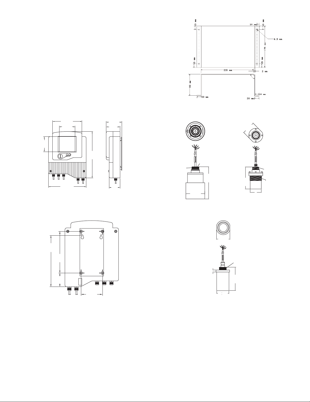
The following diagrams show the front and side views of UT, and its dimensions:
Figure 5: Panel Mount (Contact Factory)
Sensor Dimensions
Figure 1 & 2: Front and Side View
The following schematic diagrams show the wall mount and panel mount options,
with the dimensions:
Figure 3 & 4: Back View of
Series UT with Wall-Mount Plate
Page 2
25 kHz Stand and Range
UTS-12X-XXXX-X
Figure 6: Sensor Dimensions
25 kHz Long Range Sensor
UTS-13X-XXXX-X
50 kHz Sensor
UTS-2XX-XXX-X
Page 4
PECIFICATIONS
S
ERIES UTC
S
ervice: Compatible liquids.
S
Wetted Materials: ECTFE.
Ranges: (Sensor Dependent)
Short Range: 1.3 to 39.4 ft (0.4 to 12 m);
tandard Range: 2 to 82 ft (0.6 to 25 m);
S
ong Range: 2 to 131 ft (0.6 to 40 m).
L
ccuracy:
A
TC-1XX-XXX-X: 0.25% of max range;
U
UTC-2XX-XXX-X: 0.2% of max range.
Resolution: 0.04˝ (1 mm).
Temperature Limits:
TC-XX1-XXX-X: -40 to 140°F (-40 to 60°C);
U
TC-XX2-XXX-X: -4 to 140°F (-20 to 60°C).
U
emperature Compensation: Automatic.
T
Pressure Limits: Atmospheric.
Power Requirement:
UTC-XX1-XXX-X: 18 to 30 VDC 6 W;
UTC-XX2-XXX-X: 100 to 240 VAC 50/60 Hz.
utput Signal: 4 to 20 mA.
O
ax. Loop Resistance: 750 Ω @ 24 VDC.
M
lectrical Connections: Screw terminal.
E
Conduit Connection: 1/2˝ NPT, M20 x 2.5 (optional).
Enclosure Rating: NEMA 4X (IP65).
Mounting Orientation: Vertical.
Memory: Non-volatile.
isplay: LCD (6 digit).
D
nits: m, in, ft, m
U
rogramming: 4 button.
P
3
hr, GPM (interchangable).
/
Weight: (3.5 lb) 1.6 kg.
SERIES UTS
Service: Compatible liquids.
Wetted Materials:
UTS-XX1-XXX-X: Polypropylene;
UTS-XX2-XXX-X: PVDF;
UTS-XX3-XXX-X: PVDF/glass epoxy;
UTS-XX4-XXX-X: Fully coated PVDF.
Ranges:
Short Range: 1.3 to 39.4 ft (0.4 to 12 m);
Standard Range: 2 to 82 ft (0.6 to 25 m);
Long Range: 2 to 131 ft (0.6 to 40 m).
Blind Zone:
Short Range: 1.3 ft (0.4 m);
Standard Range: 2 ft (0.6 m);
Long Range: 2 ft (0.6 m).
Beam Width: 3˝ (7.6 cm) diameter.
Beam Angle: 5° @ 3 db point.
Temperature Limits: -40 to 176°F (-40 to 80°C).
Temperature Compensation: Automatic.
Pressure Limits: Atmospheric.
Transducer:
UTS-1XX-XXX-X: 25 kHz;
UTS-2XX-XXX-X: 50 kHz.
Process Connection: 2˝ NPT, 2˝ BSP (optional).
Electrical Connection: 16.4´ (5 m) 5 cond. 0.75 mm
Enclosure Rating:
UTS-XXX-1XX-X: NEMA 4X (IP65);
UTS-XXX-2XX-X: NEMA 6X (IP68).
Weight: (3.5 lb) 1.6 kg.
2
cable.
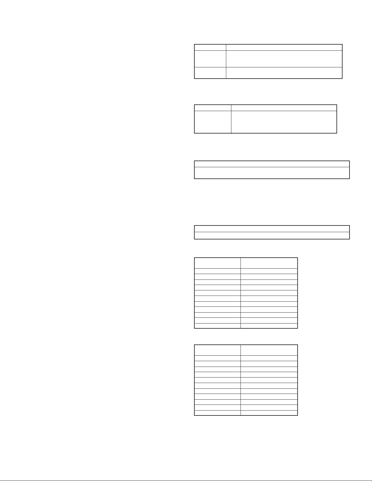
ensor Recommendations
S
TS-1XX-XXX-X:
U
5 kHz Sensor Recommendations
2
aterial
M
Coated
Aluminum
(ECTFE)
Description
Designed for complex environments with problematic
choes, such as non-conductive vapors and liquids.
e
ood performance in problematic applications.
G
sable in highly acidic or alcoholic environments. High
U
ensitivity to echoes.
s
*Consult factory
UTS-2XX-XXX-X:
0 kHz Sensor Recommendations
5
escription
aterial
M
lass reinforced
G
poxy
e
D
or liquid applications (not recommended for dusty
F
nvironments).
e
High resistance in highly acidic and alcoholic
environments. Used for rapid response.
ensor Cable Lengths
S
ll sensors are supplied with either pre cut cable or with flexible cable.
A
Sensor cable specifications: 4 wires, 0.75 mm
2
overall shielded.
NOTE:
It is recommended to use a connector when cutting/adding sensor cables (both
precut and flexible sensors).
re Cut Cable (Non Hazardous)
P
Pre cut sensor cables can be modified to fit longer and shorten length than the one
that was ordered. For example, if you ordered a sensor for the UTS-1X-XXX-X with
a 5 m/16.4 ft cable, you will be able to modify it to a range between 5 m/16.4 ft to
50 m/164 ft, or if you ordered a sensor for the UTS-1X-XXX-X with 35 m/114 ft
cable, you will be able to modify it to fit a range between 5 m/16.4 ft to 100 m/328
ft. The modifications in the cable length can be made according to following tables:
NOTES:
Sensor cable should not be cut below a minimum of 5 meters (16.4 ft) length.
UTS-1XX-XXX-X
(25 kHz) Sensor Cable
25 kHz sensor pre cut
cable length (ft/m)
16.4 ft/5 m
49.21 ft/15 m
82 ft/25 m
114 ft/35 m
164 ft/50 m
246 ft/75 m
328 ft/100 m
410 ft/125 m
492 ft/150 m
574 ft/175 m
656 ft/200 m
Can be changed to a
range of (ft/m)
16.4 ft/5 m to 164 ft/50 m
16.4 ft/5 m to 164 ft/50 m
16.4 ft/5 m to 164 ft/50 m
16.4 ft/5 m to 164 ft/50 m
16.4 ft/5 m to 164 ft/50 m
164 ft/50 m to 328 ft/100 m
164 ft/ 50 m to 328 ft/100 m
328 ft/100 m to 492 ft/150 m
328 ft/100 m to 492 ft/150 m
492 ft/150 m to 656 ft/200 m
492 ft/150 m to 656 ft/200 m
UTS-2XX-XXX-X
(50 kHz) Sensor Cable
50 kHz sensor pre cut
cable length (ft/m)
16.4 ft/5 m
49.21 ft/15 m
82 ft/25 m
114 ft/35 m
164 ft/50 m
246 ft/75 m
328 ft/100 m
410 ft/125 m
492 ft/150 m
574 ft/175 m
656 ft/200 m
Can be changed to a
range of (ft/m)
16.4 ft/5 m to 164 ft/50 m
16.4 ft/5 m to 164 ft/50 m
16.4 ft/5 m to 164 ft/50 m
16.4 ft/5 m to 164 ft/50 m
16.4 ft/5 m to 164 ft/50 m
164 ft/50 m to 328 ft/100 m
164 ft/ 50 m to 328 ft/100 m
328 ft/100 m to 492 ft/150 m
328 ft/100 m to 492 ft/150 m
492 ft/150 m to 656 ft/200 m
492 ft/150 m to 656 ft/200 m
Page 3
Page 5
lexible Cable
F
lexible sensor cables are supplied with 16.4 ft/5 m loose-end cable. However, they
F
an be modified to fit longer length than 16.4 ft/5 m. The modifications in the cable
c
ength can be made according to following tables:
l
UTS-1XX-XXX-X UTS-2XX-XXX-X
5 kHz Sensor Cable Length (ft/m)
2
6.4 to 164 ft/5 to 50 m
1
49.21 to 328 ft/50 to 100 m
328 to 492 ft/100 to 150 m
492 to 656 ft/150 to 200 m
NOTES:
ny cable length beyond 328 ft/100 m, may affect the measuring range by
A
educing the range.
r
hapter 2: Installing Series UT
C
Precautions
• Ensure that the Series UT components are mounted in an area that meets the
stated temperature, pressure and technical specifications.
Ensure that high-voltage sources or cables are at least 3.28 ft/1 m away from the
•
ensor and its cable.
s
Use round cables with minimum diameter of 6 to 7 mm to ensure that the unit
•
remains sealed to enclosure rating listed (IP65/67).
• Ensure that cables are routed correctly and tightened along walls or pipes.
• Ensure that all cables are overall shielded (sensor cable, interface cable, power
cable and current cable).
Installation and operation of this product should be performed according to the
•
nstallation and Operating Instructions; otherwise, the use of this product is
I
rohibited.
p
Installing the Series UT Sensor (UTS)
The following procedures describe sensor installation using 1˝ or 2˝ threading and
a correlating locking nut. The installation procedure is the same whether the sensor
is mounted directly on the tank or mounted on a pipe.
NOTES:
If applicable, you can also install the sensor by screwing it directly into the tank or
pipe threading. Ensure that the tank/pipe threading matches the sensor threads.
To Install the Sensor Using 1˝ Threading:
1. Open the required tank (or pipe).
2. Feed the free end of the sensor cable from the inside of the tank through the
aperture at the top of the tank until the sensor is pulled taut against the ceiling.
The threaded end of the sensor should protrude from the top of the tank.
3. Spread silicon grease around the threading to seal against leakage (you can also
use a FEP band).
4. Thread the free end of the sensor cable through a 1˝ locking nut (not supplied
with the Series UT unit). Bolt the sensor into place by securing the nut to the
sensor thread protruding from the top of the tank.
NOTES:
Tighten the nut by hand only. When tightening the nut, hold the lower part of the
sensor.
5. Wire the sensor cable to the main Series UT unit, as described on page 5.
To Install the Sensor Using 2˝ Threading (UTS-1XX-XXX-X (25 kHz) Standard
Range Sensor):
• Follow the procedure described on the previous page for 1˝ threading, using a 2˝
locking nut with the 2˝ BSP/NPT sensor threading.
50 kHz Sensor Cable Length (ft/m)
6.4 ft/5 m to 328 ft/100 m
1
28 ft/100 m to 656 ft/200 m
3
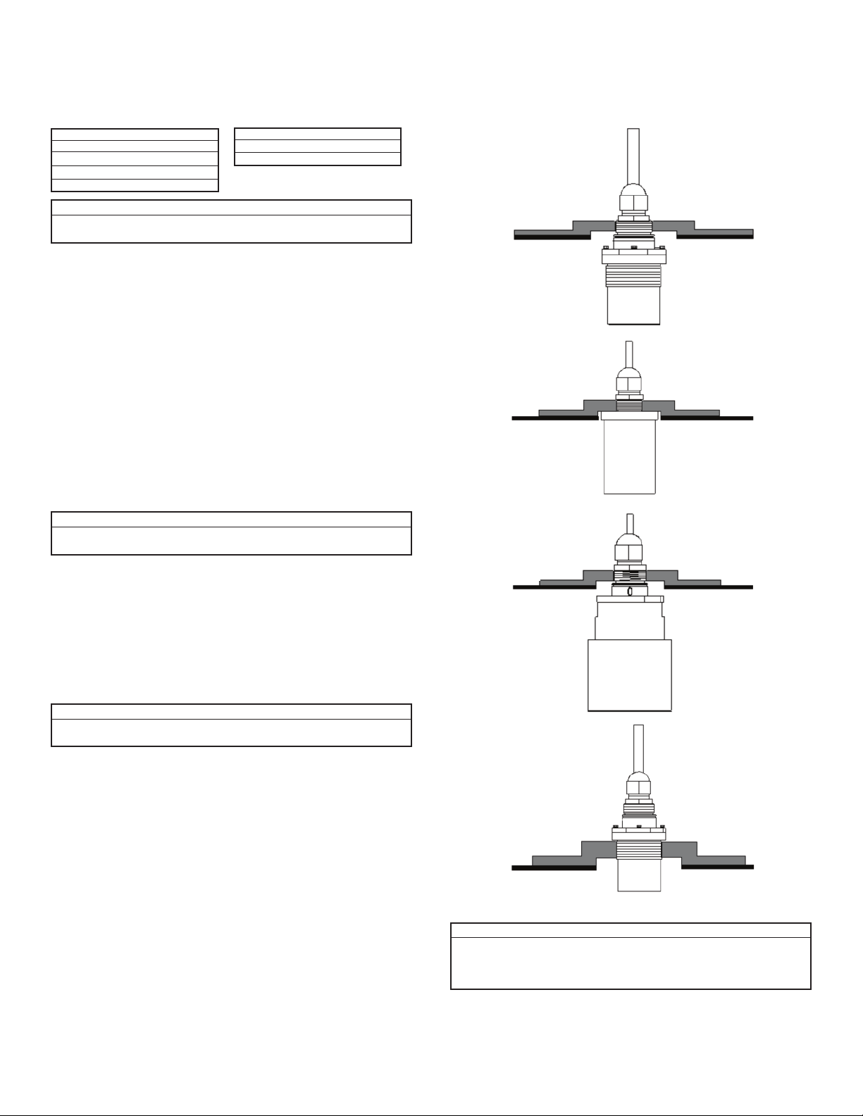
hreading Options
T
eries UT sensors are available in BSP or NPT thread types. The UTS-2XX-XXX-
S
(50 kHz) sensor can be installed using 1˝ threading. The UTS-1XX-XXX-X (25
X
Hz) sensors can be installed using 1 or 2˝ threading. (Refer to Figure 6: Series UT
k
Sensor Dimensions in Chapter 1: Introduction.)
1˝ BSP/1˝ NPT
hreading for
T
TS-1XX-XXX-X
U
25 kHz) Sensor
(
Standard Range)
(
˝ BSP/1˝ NPT
1
Threading for
UTS-1XX-XXX-X
(50 kHz) Sensor
1˝ BSP/1˝ NPT
Threading for
UTS-1XX-2XX-X
(25 kHz) Sensor
(Long Range)
2˝ BSP/2˝ NPT
Threading for
UTS-1XX-1XX-X
(25 kHz) Sensor
(Standard Range)
NOTES:
When installing a thread free flange mounted unit, you will need a 1˝ or 2˝ locking
nut (depending on the thread type used) to secure the sensor to the tank. The nut
can be purchased separately. When installing a threaded flange, ensure that it
matches the Series UT threads.
Page 4
Page 6
ensor Positioning
S
hen installing the sensor, ensure that it is:
W
Mounted above the dead-zone area (Blind Zone)
•
(blocking distance).
OTES:
N
f the device enters the dead zone, it
I
ill not measure correctly.
w
• Positioned at least 0.5 m (1.64 ft) away from
the tank walls.
• Perpendicular to the surface of the target.
NOTES:
Even the slightest difference in angle
may affect echo quality.
nstalling the Sensor via an Extension Pipe
I
f the level of the measured surface falls within the dead-zone area, you should use
I
n extension pipe to mount the sensor.
a
When using an extension pipe, ensure that:
• The sensor is positioned in the center of the
pipe.
The pipe extension is parallel to the side/tank
•
alls.
w
The tank should be empty to allow tracking of
•
alse echoes.
f
• The internal pipe diameter is at least 3˝ and 4˝
wide.
hen installing the sensor with an extension
W
ipe, follow these specifications:
p
ipe Length
P
1.64 ft (0.50 m)
OTES:
N
e advise you to consult with your local distributor prior to the installation. It is
W
ssential to run scan distance function during the installation process. It is
e
recommended to use pipes made of PVC/plastic and not stainless steel.
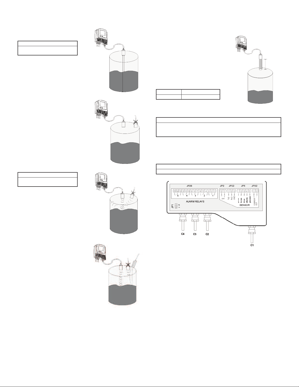
iring the Series UT Unit
W
he lower part of the Series UT unit consists of the electrical unit, which contains
T
he wiring terminals for the sensor cable and the power cable. The electrical unit
t
also contains optional connectors for monitoring of digital and analog outputs, as
well as five optional relay connectors.
NOTES:
Remove the rubber sealing from the gland before wiring the connectors.
nternal Pipe Diameter
I
3 or 4˝
Figure 10:
xtension Pipe Installation
E
• Install the sensor as far as possible from noisy
areas, such as a filling inlet.
Figure 11: Electrial Unit Using Glands/Conduits
In order to make a wiring connection, remove the ribbed faceplate covering the
electrical unit using a 3 mm allen wrench. Ensure that the cover is replaced
securely after all wiring connections are completed.
To Wire and Install the Series UT:
1. Install the sensor, as described in Installing the Series UT Sensor, page 4.
2. Route the sensor's cable (C1) from the sensor to the main unit location. Choose
a route without electromagnetic interference (electrical engines, pumps or high
voltage.
3. Wire the sensor's cable (C1) to the main unit, as described in Wiring for the
Sensor Cable, below.
4. Make any optional monitoring or relay cable connections to the main unit, as
described in the instruction manual.
5. Connect the power cable to the main unit.
6. If required, mount the main unit on the wall using the optional wall mount plate.
Page 5
Page 7

iring the Sensor Cable
W
ensor cable specifications: 5 wires, 0.75 mm
S
fter the sensor is installed on the tank, the free end of the sensor cable is
A
onnected to the electrical unit using terminal JP5.
c
2
verall shielded.
o
To Wire the Sensor Cable to JP5:
OTES:
N
nsure that the power is switched off before wiring the sensor cable.
E
. Thread the sensor cable through aperture (C1), located on the right side of the
7
eries UT electrical unit's base.
S
8. Connect each colored wire in the cable to the appropriate screw down
termination post at terminal JP5, according to the color coding given in the table
elow (if the extension cable wires are black, follow the coding given in brackets).
b
OTES:
N
P5 Post
J
1
2
3
4
5
olor
C
Green (Black 1)
Brown (Black 2)
Blue
hite (Black 3)
W
ellow
Y
Close the glands and conceal any openings to ensure sealing. Do not exceed 250inch pounds torque on installation of conduit. The O-ring is suitable for one use
only.
iring the Monitoring Cables
W
eries UT data can be monitored on a PC via an RS 485 or RS 232 connection to
S
erminal JP22. You can also connect Series UT to an analog output meter set
t
between 4 mA and 20 mA using terminal JP32. (Setting the 4 mA and 20 mA values
is described in Chapter 3, Basic Setup.)
To Wire the Digital Interface Cable to JP22:
1. Thread the required cable through the wiring apertures (C2) located at the base
of the electrical unit.
2. Connect each wire in the cable to the appropriate screw down termination post
at terminal JP22, wiring for RS-485 or RS-232, as required:
RS-485
JP22 Post
1
2
3
Wire
B
A
Ground
RS-232
JP22 Post
1
2
3
Wire
TxD
RxD
Ground
To Wire the 4 to 20 mA Cable to JP32:
1. Thread the required cable through the wiring apertures located at the base of the
electrical unit.
2. Connect the wires in the cable to the screw down termination posts at terminal
JP32. Connect the positive wire to post 1 and the negative wire to post 2.
NOTES:
Close all glands to ensure sealing. Do not exceed 250-inch pounds torque on
installation of conduit. The O-ring is suitable for one use only.
iring the VDC Power Cable
W
he free end of Series UT’s (UTC-XXX-1XX-X) power cable is connected to the
T
lectrical unit using terminal JP2 when working in VDC.
e
To Wire the Power Cable to JP2:
1. Thread the required cable through C2 aperture at the base of the electrical unit.
2. Connect the wires in the cable to the appropriate screw down termination posts
t terminal JP2. Connect the negative wire to post 2 and the positive wire to post
a
.
1
iring the VAC Power Cable
W
The free end of Series UT’s (UTC-XXX-2XX-X) power cable is connected to the
electrical unit using terminal JP1 when working in VAC.
o Wire the Power Cable to JP1:
T
. Thread the required cable through C4 aperture at the base of the electrical unit.
1
. Connect the wires in the cable to the appropriate screw down termination posts
2
at terminal JP1. Connect the zero wire to post 1 and the phase wire to post 2.
CAUTION
OTES:
N
lose all glands to ensure sealing. The O-ring is suitable for one use only.
C
HIGH VOLTAGE IN JP1!
Chapter 3: Basic Setup
This chapter describes how to set up and calibrate Series UT for accurate
measurement monitoring using the basic menu options.
eries UT is supplied with preprogrammed default settings, making it ready for
S
mmediate operation. Measurement readings are displayed on the default screen
i
as soon as the unit is powered on, as described in Default Screen, page 7.
It is recommended that you replace the default tank height value with the actual
tank height, as described in Setting the Tank Height, page 11. When using Series
UT, the tank height is calculated as the distance from the surface of the sensor to
the bottom of the tank. You should enter this value whenever tank height is
required. (For flow measurement, enter the precise flume height.)
The Series UT main menu (shown on page 7) enables you to access the primary
functions for Series UT operation, so that you can change the default settings and
calibrate Series UT, as required. You can define further specialized function options
for Series UT from the additional menu, as described in Chapter 5, Additional
Features.
Wiring the Relays Cable
Series UT’s electrical unit provides connectors at terminal JP26 for up to five
independently programmable relays. The relays can be used to initiate certain
actions, such as controlling pumps, triggering an alarm or sending a warning
message, or when a defined value is reached. (Defining values for the relays is
described in Chapter 3, Basic Setup.)
To Wire the Relays Cable to JP26 Using VDC Power:
1. Thread the required cable through apertures (C2/C3) located at the base of the
electrical unit.
2. Connect the relay cable wires to the appropriate posts, as shown in Figure 11:
Electrical Unit, page 5.
NOTES:
Close the glands to ensure sealing. The O-ring is suitable for one use only. If your
unit is equipped with conduits instead of glands, aperture C3 is not available. Use
aperture C4 instead. Do not exceed 250-inch pounds torque on installation of
conduit.
Figure 12: Series UT Main Menu Screen
NOTES:
The options displayed in the main menu depend on the Series UT model so you
may not necessarily view all the options shown in the above example.
Page 6
Page 8
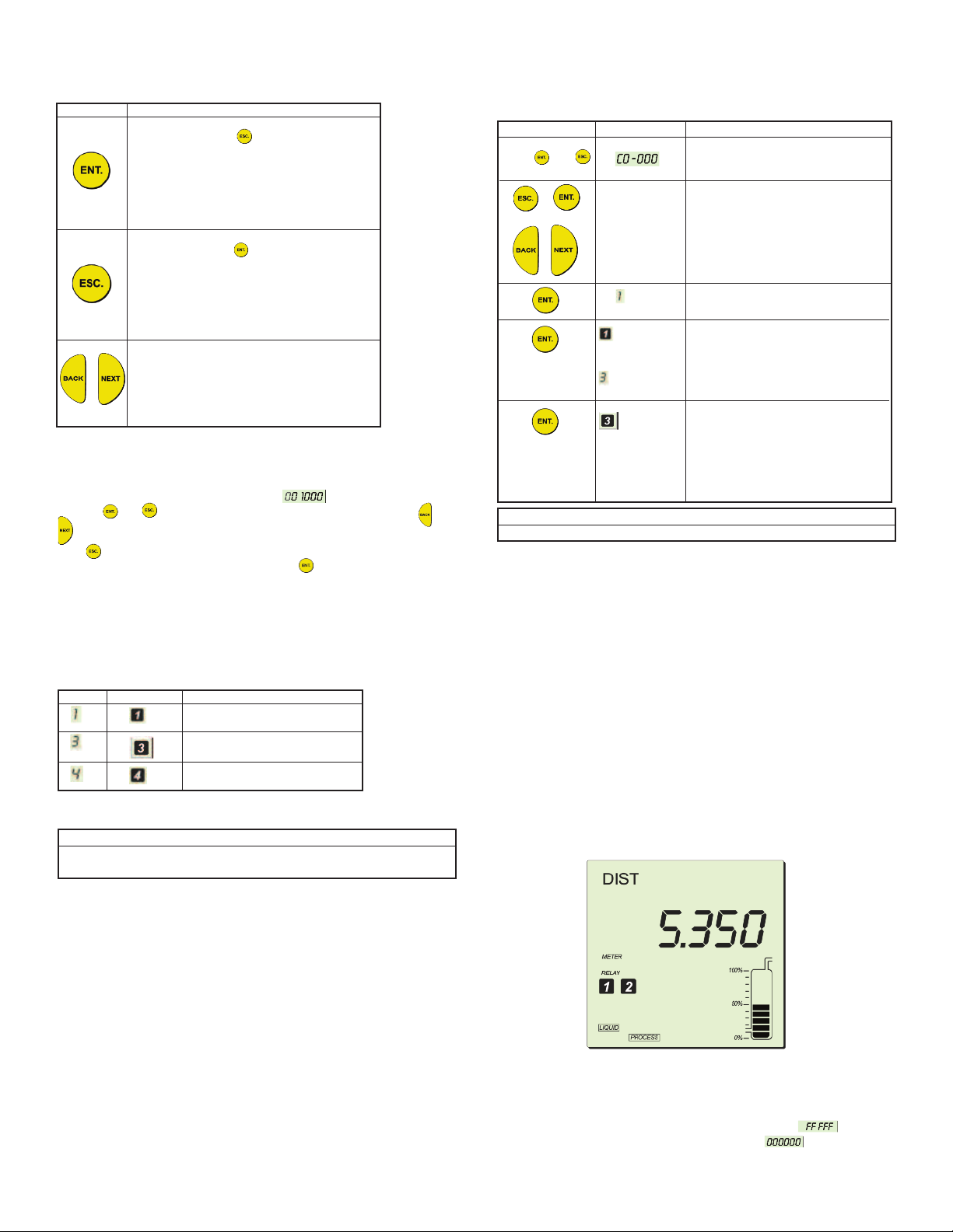
sing the Series UT Function Buttons
U
he function buttons are used to perform various operations, summarized in the
T
ollowing table.
f
utton
B
odifying Numerical Values
M
ithin some functions, the value displayed in the numerical area can be modified.
W
he digit currently available for modification is displayed flashing (flashing digits are
T
shown in gray in the illustrations, for example, ). The value is modified by
using the and buttons to move between the digits, and by using the and
buttons to scroll through the possible number values for the flashing digit. If you
press on the far left digit, you will revert either to the previous step of the function
or to the main menu, without saving. If you press on the far right digit, the new
value is saved.
Menu and Version Selection
Series UT has two menus, the main menu and the additional menu. To access each
of these, you must select the appropriate digit in the numerical area of the display
screen. After selecting the required digit (by pressing the ENT button), the
corresponding number icon flashes in the LCD, indicating that Series UT is entering
the selected version mode or menu.
Digit
The complete procedure for accessing each version mode or menu is described in
the relevant chapters of this manual.
NOTES:
The number icons also have other functions in Series UT. These include
identifying the active relay(s) for the relay function in the unit.
Uses Include:
• Accessing the menus (when pressed
imultaneously with ).
s
Accessing a function within a menu, enabling
•
ou to make modifications.
y
Moving from left to right between displayed digits
•
in the numerical area (refer to Modifying
Numerical Values, below).
• Saving changes to data.
Accessing the menus (when pressed
•
imultaneously with ).
s
Moving from right to left between displayed digits
•
n the numerical area (refer to Modifying
i
Numerical Values, below).
• Taking you back to the previous function step
(without saving changes) or back to the default
creen.
s
Moving to the next/previous function within a
•
enu.
m
• Scrolling through available data/numerical values
or
within functions.
• NEXT button only: Saving interfering signals (For
more details, see page 12).
Number Icon
Version Mode/Menu Option
Option to enter setup mode
Option to enter the main menu
Option to enter the additional menu
ccessing the Main Menu
A
his chapter describes access and setup for Series UTS and UTC.
T
he Series UT main menu screen is accessed from the default screen, using the
T
unction buttons located under the LCD.
f
Press/Action
ress and
P
imultaneously.
s
r
o
r
o
NOTES:
You can return to the default screen by pressing the ESC button.
Using the Main Menu
The BACK and NEXT buttons are used to move through the various main menu
options, with the current option indicated by a flashing display. You can access and
modify the main menu functions in any order, but you should remember that a
change to the data for one function might affect the data for another function. For
example, changing the tank height value will also change the default value for 20
mA. There are permitted minimum and maximum values for many of the functions;
refer to Appendix A, Series UT Ranges.
The level of the tank graphic displayed in the main menu screen moves up from 0
to 100% when you save an option or when Series UT is processing. After saving
an option, the main menu is displayed with the next option flashing.
Default Screen
As soon as Series UT is fully installed and powered on, the LCD displays the
default screen. The default screen provides continuously updated measurement
readings and displays the current settings for some functions (either the default
settings or the settings selected from the main menu). The relay number is
displayed for each activated relay. You can toggle between display indication types,
such as: level, distance, volume and others, by using the Series UT function
buttons (Series UT) For more details, see page 8.
Display
flashes for
pproximately 5
a
econds, then
s
is displayed.
n
flashes for
approximately 5
seconds, then
the main menu
screen is
isplayed.
d
Explanation
isplays the password window.
D
Use to enter the password code (716) in
place of the last three digits (000).
(Function button use is described using
he Series UT function buttons.)
t
equired option to enter setup mode.
R
Required option to access the main
enu.
m
A representation of the main menu
screen is shown on page 6.
Figure 13: Series UT Default Screen
The tank graphic in the default screen gives an approximate visual indication of the
current level of the tank contents, while the numerical area gives the exact reading.
If the level enters the dead zone, the numerical area displays ; if the tank
is empty, the numerical area displays the tank height. may be displayed
Page 7
Page 9

emporarily while Series UT is taking a reading.
t
ou can refresh the reading by pressing the ENT and BACK buttons
Y
imultaneously.
s
NOTES:
By default, the displayed value is in meters and gives the distance measurement,
eaning from the sensor to the level of the liquid/solid. The measurement
m
ndication mode and measurement unit can be changed, as described in Setting
i
he Indication Mode, page 8, and Setting the Measurement Unit, page 8.
t
Setting Main Menu Options
The following functions are available in the Series UT main menu.
efer to page 8.
R
Refer to page 8.
efer to page 9.
R
Refer to page 11.
efer to page 11.
R
Refer to page 11.
Refer to page 12.
Refer to page 12.
Refer to page 12.
Refer to page 12.
FLOW: The screen displays temporary flow passing through the configured
•
lume/weir. If required, you can select this option to label the reading when
f
orking in flow mode.
w
Setting an indication mode enables you to toggle between other indications types
as well, using BACK or NEXT buttons, as described in the table below*:
* Toggling between indication types is available in UTC-2XX-XXX-X only.
ndication
I
istance/Level
D
low
F
Totalization
Volume
o Set the Indication Mode:
T
ress/Action
P
isplay
D
ndication Toggle Option
I
istance/Level
D
low/Level/Distance/ Totalization
F
High)/Totalization (Low)
(
Totalization/Distance/Flow
Volume/Level/Distance
xplanation
E
se to move between the available
U
options.
r
o
ress to save
P
he selected option.
t
or example,
F
isplays the selected option for a few
D
econds and then redisplays the
s
ain menu.
m
For example, if the unit is configured for flow, you can toggle between
low/level/distance indications using the NEXT button.
f
etting the Measurement Unit
S
Series UT enables you to set the measurement unit used for the displayed
readings, according to your requirements and the measurement function. The
following measurement options are available:
• METER (default unit), INCH or FEET: Select one of these options for distance
measurements.
3
• M
/HR or G.P.M.: Select one of these options for flow measurements.
After setting the measurement unit, the selected unit flashes on the display
whenever you enter numerical values during the setup procedure. The values for
functions such as relay will be displayed in the selected measurement unit.
To Set the Measurement Unit:
Press/Action
Display
Explanation
Refer to page 13.
NOTES:
Some functions are only relevant for particular Series UT models.
You can leave the main menu and return to the default screen by pressing the ESC
button.
Setting the Indication Mode
The first function in the main menu is the indication mode. The following indication
options are available, depending on the Series UT model:
• DIST: (Default setting) The displayed reading represents the distance from the
sensor to the surface of the tank contents.
• DIA: The displayed reading represents the diameter of the measured material.
• LEVEL: The displayed reading represents the level of the contents, measured
from the bottom of the tank.
Use to move between the available
options.
or
Press to save
the selected option.
For example,
Displays the selected option for a few
seconds and then redisplays the
main menu.
NOTES:
If you select METER, any relevant flow measurements will be in metric units,
meaning M
3
/HR. The opposite also applies, so that if you select M3/HR, any
relevant distance or level measurements will be in meters.
If you select INCH or FEET, any relevant flow measurements will be in G.P.M. If
you select G.P.M., any relevant distance or level measurements will be in inches.
In case you select METER when using a FLOW model configured to show G.P.M.,
the METER sign will flash rapidly for few seconds. If you approve the selection by
pressing ENT, the flow measurement units will be in M
3
; otherwise, the
measurement units will stay in G.P.M. and vise versa.
Page 8
Page 10

etting the Series UTC Relay Values
S
ou can set the relays to five different configuration modes: Level, Distance and
Y
low (where applicable), Volume and Totalization (the last two modes should be
F
onfigured only after Volume/Totalization options were enabled in the Chapter 5,
c
Additional Features). Use NEXT or BACK buttons to toggle between modes and
ENT to select the mode. After selecting an indication mode, move on to set the first
relay parameters.
on Flow
N
pplication
Indication
ode
M
elay
R
ode
M
elays Setup Options
R
or example, if the Series UT is set to flow indication mode, the relay can be set to
F
low/distance or level values. In any other unit or SW version, the relay
f
configuration is done for level or volume values.
Each of the five relays in the Series UT allows you to define open and close values
for the switch, enabling its use for functions such as triggering an alarm or
ontrolling pumps.
c
n addition, relay four (4) can be configured to report error messages and relay five
I
(5) for flow totalization pulse setup (see detailed configuration instructions on page
10).
The relay values function as follows:
Open value: (Default = 0) The relay opens if the level measured in the tank is
•
igher than the entered open value.
h
Close value: (Default = 0) The relay closes if the level measured in the tank is
•
lower than the entered close value.
NOTES:
The indication mode default state is Level. The chosen mode will be applicable for
all five relays. The close value must be lower than the open value for each relay,
otherwise an message is displayed. An message is displayed if a
relay value is greater than the tank height value.
A
Dist. Level Vol.
ist., Level Vol.
D
low
F
pplication
A
Flow Total.
Flow, Dist.,
Level
Flow,
Total.
o Set the Relay Values for Level or Distance:
T
ress/Action
P
to enter relay
setup.
o assign an
t
ndication mode for
i
he relays.
t
o enter open
t
ode.
m
r
o
or
to enter values
for the relay.
ress at the end
P
f entering a value
o
for relay 1, to
enter close value
parameters.
ress on the far
P
right digit to save
the value.
isplay
D
a
a
nd
nd
and
xplanation
E
With the RELAY icon flashing.
hoose the desired relay configuration
C
ode: Level, Distance, Flow,
m
otalization or Volume. Use the NEXT
T
utton to toggle between indication
b
modes and ENT to select the mode.
Enters the open values mode of the
elay setup. The appropriate relay
r
umber flashes throughout the process
n
f defining values for that relay.
o
Displays 0 or the previously entered
relay value.
Use to enter the relay value.
nters close values mode of the relay
E
etup. Enter and save the close values
s
n the same way as described above for
i
the open values.
Repeat the previous steps to set an
open/close values for each relay to be
used. (If you do not want to set a value
for every relay, use the Esc button to
exit the relays set-up mode.)
In case of no measurement (caused by electronic problem or acoustic
interference) relays will switch to Close state.
For safety reasons relays parameters will reset when the following parameters will
be modified: Tank height, relays indication mode (Level/ Distance/Flow),
measurement mode (except when changing from Level to Distance and vise
versa) Flume/Weir type, measurement units, strapping table.
NOTES:
In DISTANCE mode, the OPEN value entered for a relay should be greater than
the CLOSE value entered for the relay, otherwise an is displayed.
Relay OPEN and CLOSE values in DISTANCE mode should be different by a
resolution of more than 3 cm.
Relay values can be configured in two separate screens when set to flow, volume
or totalization (after setting the Series UT was set to of these indications).
Press/Action
to enter relay
setup.
to assign an
indication mode.
or
As shown in the above example, relay values were configured in the following way:
000001 was entered in the high numbers H=1, and 20,000 was entered in the low
numbers L=20,000, which mean a total value of 120,000 gallons.
Display
For example,
and
For example,
Explanation
With the RELAY icon flashing.
Choose FLOW from the optional modes,
and press ENT.
Select the relay number you wish to
configure, using NEXT and BACK
buttons and press ENT. Select OPEN
and press ENT.
This screen allows you to enter up to
four digits of high numbers of flow
values.
Use this screen to enter low numbers of
up to five digits of flow values.
Enter relay values for Close mode, as
described above for Open mode.
Page 9
Page 11

NOTES:
he same configuration applies when selecting volume mode for the relays.
T
elays OPEN and CLOSE values should differ when working in FLOW or
R
OTALIZATION mode.
T
etting Relay 4 to Report Errors
S
This mode enables you to use the relay as a trigger to set on an alarm or siren in
case the unit produces inaccurate measurement results due to an electrical failure
or acoustic problem. You can configure relay 4 to report errors or to remain in
ormal set-up mode. Once the error mode is enabled and one of the situations
n
escribed below appears, the relay will be closed and an error message will show
d
n the unit display. These error messages will describe the following situations:
o
• - In case of lost echo or when measurement result is higher than
tank height.
• - Near dead zone.
he relay will remain in Open mode as long as the unit displays proper
T
easurement values.
m
o Set Relay 5 for Pulse Indication:
T
Press/Action
r
o
r
o
o select enable
t
r disable mode.
o
o select a
t
ulse value from the
p
ist.
l
Display
or example,
F
0,000 m
1
3
.
Explanation
ove to relay 5 using NEXT or BACK
M
uttons and ENT to enter the desired
b
peration mode.
o
hoose tot En to enable pulse indication
C
ption or tot-ds to disable this option.
o
Select a pulse value from the list of
optional values using NEXT button and
NT to save your selection. Optional
E
alues are between 1 to 100,000.
v
To Set Relay 4 for Error Report:
ress/Action
P
isplay
D
xplanation
E
Move to relay 4 using NEXT or BACK
buttons and ENT. to enter the relay
r
o
mode.
hoose Err En to enable error alert or
C
rr dS to disable.
E
Setting relay 5 for Flow Totalization Pulse Indication
You can choose to set relay number five (5) for flow totalization pulse indication or
to remain in normal set-up mode. This option enables you to reserve the
accumulated value gathered by the unit by using an external counter. In this way,
the total value will be reserved even if the unit will be replaced. Once set for this
option, the relay will generate a pulse per Xm
3
or Gallons of flow, depending on the
value that you have selected from the following list (you can define the X value): 1,
10, 100, 1000, 10000, 100000. An electrical pulse will be generated whenever the
relay total flow value will be larger than the value selected from the list. You can
also choose a pulse width between 20 to 2000 milliseconds with a resolution of 10
milliseconds to match your equipment requirements. For example, the relay will
generate a pulse with a duration of 1000 ms, and each time the value of flow will
reach 10,000 M
3
(provided that this value was selected from the optional list of
values).
NOTES:
Prior to setting relay 5 for pulse indication, you should configure the Series UTC
for Totalization (see Chapter 5, Additional Features).
To configure relay 4 and 5 to work in a normal setup, select Open or Close mode
and enter the required parameters. When configure relay 5 as tOt En, the active
options are tOt En and tOt dS. To go back to normal work press tOt dS.
to enter a pulse
width value (as
pecified in your
s
quipment).
e
For example,
10,000 m
Following the above configuration example, a pulse with duration of 1000 ms will
ccur each time the total value of flow will reach 10,000 m
o
etting the Series UTC-1XX-XXX-X Relay Values
S
Enter a pulse width value between 20
milliseconds and 2000 milliseconds (the
resolution of 10 milliseconds).
3
.
3
.
You can set up to five relay switches for Series UTS. Each relay enables you to
define open and close values for the switch, for functions such as triggering an
alarm.
The relay values function as follows:
• Open value: (Default = 0) The relay opens if the level measured in the tank is
higher than the entered open value.
• Close value: (Default = 0) The relay closes if the level measured in the tank is
lower than the entered close value.
NOTES:
The close value must be lower than the open value for each relay, otherwise an
message is displayed.
An message is displayed if a relay value is greater than the tank height
value.
In case of no measurement (caused by electronic problem or acoustic
interference) relays will switch to Close state.
For safety reasons, relays parameters will reset when the following parameters will
be modified: Tank height, relays indication mode (Level/ Distance/Flow),
measurement mode (except when changing from Level to Distance and vise
versa) Flume/Weir type, measurement units, strapping table.
The result of the totalization amount is updated every 30 seconds.
Page 10
Page 12

o Set the Relay Values for Level or Distance:
T
Press/Action
o enter relay
t
etup.
s
to enter open
mode.
r
o
r
o
ress on the far-
P
right digit to save
the value.
etting the 20 mA/4 mA Levels
S
Series UT enables you to set height, volume or flow values to be used as 20 mA
and 4 mA marks. These values can be used for remote monitoring of tank level,
volume or flow using an analog meter. The analog output indicates the current
depth in the tank, or the current flow level, as a point on the meter range between
mA and 20 mA. The default value for 20 mA is the tank height (or the maximal
4
olume value), and for 4 mA the default value is 0 (or the minimum volume value).
v
NOTES:
The values for 20 mA and 4 mA must be different, otherwise an message
is displayed. Both must also be less than the tank height value, otherwise an
message is displayed.
In both distance and level measurement modes, the dead zone area affects the
maximum values that can be used for 20 mA/4 mA levels. For UTS-X1X-XXX-X
models, the maximum 20 mA/4 mA value is tank height minus 0.6 m/1.9 ft. For
UTS-X2X-XXX-X and UTS-X3X-XXX-X models, the maximum 20 mA/4 mA value
is tank height minus 0.4 m/1.3 ft.
To Set the 20 mA/4 mA Levels:
Press/Action
to enter 20 mA
or 4 mA setup.
or
or
The values of 4 to 20 mA are application dependable. For example, when
measuring distance, the value will be in distance (same for level).
NOTES:
VOLUME values in 4 to 20 mA are represented by six digits (the same applies for
FLOW values). TOTALIZATION values are represented by large numbers and
therefore require two separate screens for high (H) and low (L) numbers (as
explained on page 10).
Display
and
and
Display
Explanation
ith the RELAY icon flashing.
W
nters the open values mode of the
E
relay setup. The relay number flashes
throughout the process of defining its
values.
isplays 0 or the previously entered
D
elay value.
r
epeat the previous steps to set an
R
pen/ close values for each relay to be
o
used.
Explanation
With the required option flashing in the
main menu.
Displays the default value or the
previously entered 20 mA or 4 mA value.
Use to enter the new value. (Function
button use is described on
page 6.)
etting the Flow Measurements
S
he PARSH.FLUM function enables you to set flume/weir types and measurements
T
or Series UT open channel models. Refer to Chapter 4, Series UT Open Channels,
f
or further information.
f
Setting the Tank Height
You can enter the height of your tank using the TANK h function. The default value
s the maximum value in the relevant measurement range for your Series UT (refer
i
o the range table in Appendix A, Series UT Ranges). If you enter a value that
t
xceeds this maximum value, an error message is displayed.
e
Figure 14: Tank Height
Setting the tank height will not influence the measuring range or the accuracy of the
evice, which is calculated from the measuring range. Refer to the specifications
d
ables in Chapter 1, Introducing Series UT.
t
OTES:
N
henever the tank height is required, you should enter the distance from the
W
urface of the sensor to the bottom of the tank. In order to obtain accurate
s
measurement results, it is most recommended to perform this operation when the
tank is empty. For flow measurement, enter the precise flume height.
If the entered tank height value is less than a value previously entered for the 4
mA, 20 mA or Relay functions, the value for that function will automatically revert
to the default value.
To Set the Tank Height Value:
Press/Action
or
to save the
selected option.
and
or
Display
for example.
For example
meters.
Explanation
Select the desired measurement method
from the indication modes: DIST, LEVEL,
DIA. Using NEXT or BACK buttons.
Displays the selected option for a few
seconds and a flashing tank graphic.
Move on with the NEXT button to select
measurement units: METER, INCH,
FEET. Press ENT to save your selection.
Move with NEXT or BACK button to
tank h.
Displays the last saved tank height or
the default value.
Page 11
or
Use to enter the new value.
Page 13

etting the Application Type
S
he Series UT main menu displays (by default) LIQUID for models intended for
T
iquid. Series UT model intended for diameter displays SOLID, LIQUID,
l
TORAGE I, II and PROCESS (refer to Chapter 6, Diameter Mode Setup).
S
When Series UT unit is configured as either LIQUID or FLOW (open channel)
model, selecting FLOW option from the indication mode automatically selects the
LOW option in the application types menu. This should be done before entering
F
alues for other functions, so that all values are automatically adjusted for flow.
v
To Set the Application Type:
ress/Action
P
Setting the Operation Modes
The operation modes function enables you to set Series UT to compensate for
environmental conditions that affect the measurement readings.
For diameter applications, available only for Series UTC model, refer to Chapter 6,
(
iameter Mode Setup).
D
isplay
D
or example.
F
Explanation
ith the required option flashing,
W
depending on the type of model in use.
isplays the selected option for a few
D
econds, and then re-displays the main
s
enu.
m
etting the Sensor Offset
S
eries UT takes measurements from the tip of the sensor. However, when the
S
ensor is located at a point that is above or below the true height of the tank, you
s
an use the MAN function to enter the difference. This may be required, for
c
example, if the sensor is installed at the top of an external pipe, or at the base of
an internal pipe in the tank.
hen the sensor is located above the tank height, the difference must be
W
ubtracted from the actual measurements, so the offset distance is entered as a
s
egative value and vise versa. The maximum permitted offset value is 2.0 m, and
n
he minimum permitted value is -2.0 m. Values can be entered in meter units only.
t
To Set the Sensor Offset Value:
Press/Action
or
r
o
Display
or
xplanation
E
With the required option flashing.
efault value.
D
Use to toggle the first digit between a
negative (-) or positive (0) value.
ontinue to enter new values for the
C
emaining five digits.
r
The modes settings are defined by making a selection from the STORAGE I,
STORAGE II and PROCESS options in the main menu; in some cases in
combination with the selection of the LIQUID application. The mode functions and
setup are described in the following sections.
NOTES:
The operation modes are not relevant for flow applications. If one of the
STORAGE I, STORAGE II or PROCESS options is selected when Series UT is in
FLOW application mode, an warning message is displayed and Series
UT reverts to distance mode. You must then reset the unit to flow mode.
Liquid Modes
Three modes are available for Series UT liquid application models. Each mode is
recommended for use as follows:
• : Recommended in the following conditions:
• Wavy surfaces
• Slow filling/emptying rate
• Applications where the sensor is installed near the tank wall
• : (Twice as fast as STORAGE I.)
Recommended in the following conditions:
• Reasonable surface conditions
• Applications requiring fast readings
NOTES:
STORAGE I and STORAGE II liquid modes are not suitable for measuring
surfaces with foam, since these modes cannot perform signal processing.
• : This mode is suitable for applications where a fast reading is more
important than precision. A reading will be displayed within a short
time, even if the signal processing procedure was not completed.
Recommended in the following conditions:
• Foamy top surface
• Presence of agitation
• Presence of vapor
• Applications requiring very fast readings
r
o
Setting the Scan Distance Values
Figure 15: Scan Distance Process
Up to eight interfering signals (false echoes) can be located by Series UT and
stored in its memory. The false echoes, which may be caused by obstructions such
as a tank agitator or a side wall, can generate false readings and so interfere with
the true scanning of the tank contents. Defining interfering signals is done while the
tank is empty.
Each scan distance reading is stored as an interfering signal until a reading is
achieved that indicates the true echo. If eight interfering signals are already stored
and a ninth reading is received, the first value stored is deleted and the new one
saved.
Page 12
Page 14

he scan distance function is accessed from the default screen. AUTO. CAL is
T
isplayed at the base of the display screen during the scan distance operation,
d
ndicating that you are working in scan distance mode.
i
OTES:
N
he reading of the actual target height may not be exact; for example, a target
T
height of 6 m may give a reading of 5.998.
o Set Scan Distances:
T
Press/Action
From the default
creen, press
s
nd
a
isplay
D
and
Explanation
Displayed temporarily while Series UT
earches for an interfering signal.
s
o View Processor Information:
T
ress/Action
P
In the main menu
display, press
nd
a
imultaneously.
s
r
o
isplay
D
xplanation
E
Use to enter the value 000.003.
simultaneously.
NOTES:
o not press any key while the SEARCH message is displayed.
D
Press/Action
(Wait a few
econds.)
s
NOTES:
Pressing the NEXT button saves identified interferences. Pressing the ENT button
exits the function while saving the true echo value.
Clearing the Scan Distance Values
The AUTO function enables you to clear all saved scan distance values. (Refer to
Setting the Scan Distance Values, page 12, for a description of how to set the scan
distance values.)
To Clear Scan Distance Values:
Press/Action
or
NOTES:
If the indication at the base of the default display screen is lit, it might be a
sign of acoustic interferences in the application. It is likely that Series UT will
overcome these interferences (i.e. display a correct value), by using a different
transmission sequence.
isplay
D
For example,
For example,
Display
Explanation
Displays the depth of the interfering
signal.
aves the interfering signal, then
S
earches again and displays the next
s
reading. Continue this process to save
up to eight interference readings.
Actual target height reading indicates
hat there are no more interfering
t
ignals.
s
Saves the true echo value and
completes the scan distance operation.
Explanation
Select AUTO function using Next
or Back buttons.
With the required option flashing.
or
Press on the
ar right digit.
f
r
o
Chapter 4: Series UT Open Channels
This chapter describes how to set flow measurement parameters for open channels
using Series UT models, and explains the flume/weir codes methodology used
when setting up flow measurements.
NOTES:
Refer to Chapter 3, Basic Setup, for an explanation of accessing and using the
Series UT main menu and function buttons.
Selecting the Flow Measurement Settings
The PARSH.FLUM function in the main menu enables you to select one of the
preset flumes/weirs settings for flow measurements.
When setting flow measurement parameters, the flume/weir type value (X) is
entered first, followed by the letter (U) or (E) as an indication for American or
European open channel flow standard, and followed by the code value (YY) that
represents the appropriate flume/weir dimensions, in the following format: .
The default is European standard. The open channel types and codes are
described in Open Channels Flow Measurements, page 14.
If you wish to insert custom flume measurements, you must enter .001 for this
function. This entry will automatically initiate an additional menu function (Pr 1),
enabling manual insertion of custom flume values in an accordance table, as
described in Chapter 5, Additional Features.
For example,
or example,
F
The version number of the screen
processor is displayed.
se to scroll through the version number
U
and absolute address for each
processor.
ress at any time to return to the main
P
enu.
m
Viewing Processor Information
You can view the version number and absolute address for each of the three
processors contained in Series UT, as follows:
• Screen processor, indicated by S before the code
• Main processor, indicated by h before the code
• Co processor, indicated by C before the code
Page 13
Page 15

o Select the Flow Measurement Settings:
T
ress/Action
P
r
o
r
o
Open Channels Flow Measurements
The flume/weir type code methodology used when setting up open channels is
based on three digits: X E/U YY
here:
W
refers to the particular flume/weir type
X
/U refers to European or American standard
E
YY refers to the specific flume/weir dimensions
Flume/Weir Types
This is the first value (X) entered for the PARSH.FLUME function. The following
flume/weir types are available both in European and American standard:
European Standard
Type (X)
Pages 14-16
Rectangular Suppressed
1
Sharp-Crested Weir, Page 14
Rectangular Contracted Sharp-
2
Crested Weir, Page 14
Trapezoidal (Cipolletti) Sharp-
3
Crested Weir, Page 14
V-notch (Triangular) Sharp-
4
Crested Weir, Page 15
Khafagi-Venturi Flume, Page 15
5
Parshall Flume, Page 15
6
Palmer Bowlus Flume
7
Trapezoidal Throat CrossSelection, Page 15
H Flume, Page 16
8
Neyrpic Venturi Flume/Long-
9
Base Weir, Page 16
isplay
D
xplanation
E
ith the required option flashing in the
W
main menu.
Displays the last saved flow
easurement setting or default value.
m
Use to select a new type value (X).
he last two digits of the display flash.
T
Use to select a new flume/weir length
code (YY), that corresponds to the type
(X) previously selected. (The two digits
are modified as one unit.)
he selected values are saved.
T
American Standard
Pages 16-18
Rectangular Suppressed SharpCrested Weir, Page 16
Rectangular Contracted SharpCrested Weir, Page 16
Trapezoidal (Cipolletti) SharpCrested Weir, Page 16
V-notch (Triangular) Sharp-Crested
Weir, Page 17
Parshall Flume, Page 17
Palmer Bowlus Flume Trapezoidal
Throat Cross-Selection, Page 17
H Flume, Page 17
Leopold-Lagco Flume,
Page 18
lumes/Weirs - European Standard
F
ectangular Suppressed Sharp-Crested Weir (Type 1)
R
ode (YY)
C
Figure 11: Rectangular Suppressed Sharp-Crested Weir
ectangular Contracted Sharp-Crested Weir (Type 2)
R
Code (YY)
Figure 12: Rectangular Contracted Sharp-Crested Weir
Trapezoidal (Cipolletti) Sharp-Crested Weir (Type 3)
Code (YY)
C
01
02
03
4
0
5
0
6
0
7
0
08
Crest Length (cm)
01
02
3
0
4
0
05
06
07
08
09
10
Crest Length (cm)
01
02
03
04
05
06
07
08
rest Length (cm)
0
2
0
4
0
6
80
100
150
00
2
00
3
20
30
0
4
0
5
60
80
100
150
200
300
30
45
60
80
100
150
200
300
Page 14
Figure 13: Trapezoidal (Cipolletti) Sharp-Crested Weir
Page 16

rapezoidal (Cipolletti) Sharp-Crested Weir (Type 3)
T
ode (YY)
C
Figure 14: V-Notch (Triangular) Sharp-Crested Weir
Khafagi-Venturi Flume (Type 5)
ode (YY)
C
1
0
2
0
3
0
04
05
06
7
0
ritish Standard
B
8
0
9
0
10
F
1
0
2
0
03
04
05
06
07
08
09
V-Notch Angle (°)
90
60
3.8
5
5
4
0
3
8.4
2
22.5
90
5
4
2.5
2
0 (cm)
lume Type
Q
Q
QV 304
QV 305
QV 306
QV 308
QV 310
QV 313
QV 316
b
V 302
V 303
1
3
40
50
60
80
100
130
160
arshall Flume (Type 6)
P
Code (YY)
0
0
0
0
05
06
07
0
0
1
1
12
13
14
1
2
0
Figure 16: Parshall Flume
Palmer Bowlus Flume Trapezoidal Throat Cross-Selection (Type 7)
Code (YY)
01
02
03
04
05
06
07
08
09
10
hroat Width (in)
T
1
2
3
4
8
9
0
1
5
1
2
3
6
9
2
1
8
1
24
36
48
0
6
2
7
6
9
20
1
144
Conduit Diameter (in) D
6
8
10
12
15
18
21
24
27
30
Figure 15: Khafagi-Venturi Flume
Figure 17: Palmer Bowlus Flume Trapezoidal Throat Cross-Selection
Page 15
Page 17

Flume (Type 8)
H
Code (YY)
Neyrpic Venturi Flume/Long-Base Weir (Type 9)
01
02
3
0
4
0
5
0
6
0
07
08
lume Size (ft)
F
.5
0
.75
0
1
1.5
2
.5
2
3
.5
4
Figure 18: H Flume
Code (YY)
01
2
0
03
04
05
06
7
0
8
0
09
Measurement Point (cm)
enturi Flume Type
V
253AX
1
1253AY
253AZ
1
253A
1
253B
1
1253C
1253D
1253E
1253F
lumes/Weirs - American Standard
F
Rectangular Suppressed Sharp-Crested Weir (Type 1)
5
7
9
4
1
8
1
3
2
28
41
igure 21: Rectangular Suppressed Sharp-Crested Weir
F
Rectangular Contracted Sharp-Crested Weir (Type 2)
Code (YY)
0
0
0
0
05
06
07
0
0
ode (YY)
C
1
0
02
03
04
05
06
07
08
09
rest Length (in)
C
1
2
3
4
8
9
Crest Length (in)
2.00
1
18.00
24.00
30.00
6.00
3
8.00
4
0.00
6
2.00
7
96.00
12.00
8.00
1
4.00
2
0.00
3
36.00
48.00
60.00
72.00
96.00
Long-Base Weir
Figure 19: Neyrpic Venturi Flume
Code (YY)
Figure 20: Long-Base Weir
Long Base Weir Type
10
11
12
13
1245A
1245B
1245C
1245D
Figure 22: Rectangular Contracted Sharp-Crested Weir
Trapezoidal (Cipolletti) Sharp-Crested Weir (Type 3)
Code (YY)
01
02
03
04
05
06
07
08
09
Crest Length (in)
12.00
18.00
24.00
30.00
36.00
48.00
60.00
72.00
96.00
Page 16
Figure 23: Trapezoidal (Cipolletti) Sharp-Crested Weir
Page 18

-Notch (Triangular) Sharp-Crested Weir (Type 4)
V
igure 24: V-Notch (Triangular) Sharp-Crested Weir
F
arshall Flume (Type 5)
P
Code (YY)
01
0
0
0
0
Code (YY)
2
3
4
5
01
02
03
04
05
06
07
8
0
9
0
0
1
11
12
13
14
15
16
-Notch Angle (°)
V
9
60
45
30
2.5
2
Throat Width (in)
0
12
18
2
3
3
48
60
72
96
120
144
almer Bowlus Flume Trapezoidal Throat Cross-Selection (Type 6)
P
Code (YY)
1
2
3
6
9
4
0
6
igure 26: Palmer Bowlus Flume Trapezoidal Throat Cross-Selection
F
H Flume (Type 7)
Code (YY)
Flume Size (in)
01
02
03
04
05
06
07
08
onduit Diameter (in) D
C
1
0
2
0
3
0
4
0
05
06
07
8
0
9
0
0
1
1
1
12
13
14
5
1
6
1
Measurement Point (in)
6
9
12
18
24
30
36
54
4
6
8
0
1
2
1
5
1
8
1
21
24
27
0
3
6
3
2
4
8
4
60
72
11.02
16.14
1.96
2.75
3.54
5.51
7.08
9.05
Figure 25: Parshall Flume
Figure 27: H Flume
Page 17
Page 19

Leopold-Lagco Flume
Type 8)
(
Chapter 5: Additional Features
This chapter describes the functions available in Series UT’s additional menu.
The additional menu functions enable you to calibrate UT to perform the following
tasks:
• Present scanning results in volume format
• Present scanning results as a total accumulative value for flow
• Present scanning results as an accumulative sum for diameter
• Calculate volume for different tank types
• Calculate flow measurements for custom flumes
• Calculate results in alternative measurement units
• Adjust results when there is interference from a conical tank ending
• Allow compensation of different types of gas.
NOTES:
The additional menu functions are available via the Series UT display.
To Access the Additional Menus:
Press/Action
(after entering the
password code)
Code (YY)
01
0
0
0
0
06
07
08
0
1
1
1
13
14
15
1
1
Figure 28: Leopold-Lagco Flume
Display
2
3
4
5
9
0
1
2
6
7
rest Length (in)
C
4
6
8
0
1
2
1
5
1
8
1
21
24
30
6
3
2
4
8
4
4
5
60
66
72
Explanation
Required option to enter setup
mode.
hapter 6: Troubleshooting Series UT
C
his chapter describes the error messages displayed when an illegal value is
T
ntered for a Series UT function, or when an option is selected that is not
e
pplicable for the specific Series UT model you are using. If an illegal value is
a
entered, the appropriate error message is displayed flashing while the level of the
tank graphic on the bottom right of the screen moves up from 0 to 100%. The
umerical area then displays , enabling you to enter a new value for
n
he function. If an illegal option is selected, an error message is displayed while
t
the tank graphic fills, and the display then reverts to the menu selection.
he possible error messages are as follows:
T
rror
E
22 mA/3.7 mA Signal Error Messages
The following list of messages will appear on the display and coincides with a 22
mA or 3.7 mA (depends on your set-up) analog current error output signal (the
default is set to 22 mA):
Error
Description
The value entered is greater than the maximum
ermitted value.
p
he value entered is less than the minimum
T
ermitted value.
p
The Close value entered for a relay is greater
than the Open value entered for the relay.
The value entered for 4 mA is equal to the value
entered for 20 mA.
he selected function/option is not applicable for
T
he Series UT model in use.
t
he value entered for the 20 mA, 4 mA or Relay
T
function is greater than the tank height.
The value entered for the tank height is greater
than the maximum value supported by the Series
UT model in use.
he measurement unit selected is not applicable
T
or the Series UT model in use.
f
he Open value entered for the relay is greater
T
than the Close value entered for the relay (in
Distance mode).
A strapping table was not entered under volume
mode or a flume/weir type was not entered under
flow mode.
The value entered for the tank height is smaller
than the actual height, as measured by Series UT.
If displayed at the base of the display screen, this
indicates a problem with the current procedure, for
example, acoustic interference.
Description
Tank is empty or echo is lost
The sensor is located near the dead zone
flashes for
approximately 5
seconds, then
is displayed.
flashes for
approximately 5
Use or to
change the display to
, then press .
NOTES:
For Series UTS models: Press once on the ESC. button to return to the main
menu, and twice to return to the default screen.
For Series UTC models: Press once on the ESC. button to return to the default
screen.
seconds, then
is displayed.
Use or to scroll
through the additional menu
options.
Page 18
Page 20

ppendix A: Series UT Ranges
A
his appendix provides the maximum and minimum permitted values for the main
T
enu functions in the Series UTS and Series UTC units.
m
Permitted Values for Series UTS
Paper Roll and
urface
S
easurement
unction
F
Tank height
(maximum)
iquids, flow
L
Permitted Values
or Series UTC
f
tandard Range:
S
0 m/65 ft 25 m
2
82 ft
/
Long Range:
30m/98ft
olid, Liquid and
S
low Applications
F
Liquid and Flow:
2 m/39 ft
1
M
pplications
A
m/9.8 ft
3
40 m/131 ft
ank height
T
.6 m/1.9 ft
0
.4 m/1.3 ft
0
.5 m/1.3 ft
0
(minimum)
Relay
mA level
4
20 mA level
mA level for
4
low
f
easurement
m
20 mA level
for flow
measurement
Manual
rom 0 up to
F
maximum tank
height
From 0 up to
maximum tank
eight
h
rom 0 up to
F
aximum tank
m
height
rom 0 up to
F
3
5,500 m
5
244,200 G.P.M.)
(
From 0 up to
55,500 m
h
/
3
/h
(244,200 G.P.M.)
From -2 m up to 2 m
From 0 up to
maximum tank
height
rom 0 up to
F
aximum tank
m
eight
h
From 0 up to
maximum tank
height
From 0 up to 55,500
3
m
/h (244,200
G.P.M.)
From 0 up to 55,500
3
m
/h (244,200
.P.M.)
G
rom -2 m up to 2 m
F
From 0 up to
maximum tank height
rom 0 up to
F
aximum tank height
m
From 0 up to
maximum tank height
Not applicable for this
application
Not applicable for this
application
rom -2 m up to 2 m
F
MAINTENANCE/REPAIR
Upon final installation of the Series UT, no routine maintenance is required. The
Series UT is not field serviceable and should be returned if repair is needed (field
repair should not be attempted and may void warranty).
ppendix B: Gas Factor Table
A
This following table contains 33 different types of gas and their factor for
ompensating sound velocity. Entering the desired factor (refer to Chapter 5,
c
dditional Features for more details) will immediately change the measurement
A
esults to fit your application requirements.
r
Factor
0.62
.63
0
.74
0
.54
0
.99
0
1.26
0.92
0.53
.41
0
.37
0
.56
0
0.77
1.01
0.38
0.68
.71
0
.90
0
.71
0
0.95
2.93
3.79
0.89
0.62
1.29
0.71
.30
1
.01
1
.63
0
1.02
0.72
0.61
0.57
ymbol
S
C
2h4o2
C3h6o
C
o
2h4
C
o
2h3c1
C
2h2
H3n
r
A
C
6H6
r
B
2
brclf
C
2
CH3COCH2CH
CO
2
CO
CI
C
4
l
C
2
C2h6o
C
2h6
C2h6o
C
2h4
He
H
2
H2S
C
o
3h8
CH
4
h
C
6n2
e
N
N
2
CH3NO
2
O
2
C3H
8
C3H8O
C
O
4H8
as
G
cetic Acid
A
Acetone
Acetaldehyde
Acetyl Chloride
cetylene
A
mmonia
A
rgon
A
enzene
B
Bromine
Bromochlorodifluoromrthane
Butanone
3
arbon Dioxide
C
arbon Monoxide
C
arbon Tetrachloride
C
hlorine
C
Dimethyl Ether
Ethane
Ethanol
Ethylene
elium
H
ydrogen
H
Hydrogen Sulfide
sopropyl Alcohol
I
ethane
M
ethyl Hydrazine
M
Neon
Nitrogen
Nitromethane
Oxygen
Propane
Propanol
Tetrahydrofuran
WARRANTY/RETURN
Refer to “Terms and Conditions of Sale” in our catalog or on our website. Contact
customer service to receive a Return Goods Authorization number before shipping
your product back for repair. Be sure to include a brief description of the problem
plus any relevant application notes.
Page 19
©Copyright 2013 Dwyer Instruments, Inc. Printed in U.S.A. 6/13 FR# R2-443909-00 Rev. 1
DWYER INSTRUMENTS, INC.
Phone: 219/879-8000 www.dwyer-inst.com
P.O. BOX 373 • MICHIGAN CITY, INDIANA 46360, U.S.A. Fax: 219/872-9057 e-mail: info@dwyer-inst.com
 Loading...