

Page 1
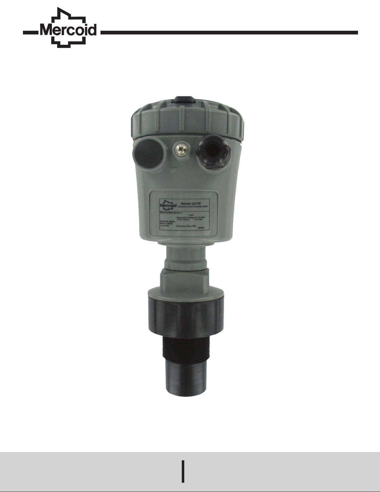
Model ULTM Ultrasonic Level Transmitter
TM
Specifications - Installation and Operating Instructions
Bulletin L-ULTM
DWYER INSTRUMENTS, INC.
Phone: 219/879-8000 www.dwyer-inst.com
P.O. BOX 373 • MICHIGAN CITY, INDIANA 46360, U.S.A. Fax: 219/872-9057 e-mail: info@dwyer-inst.com
Page 2

able of Contents
T
able of Contents . . . . . . . . . . . . . . . . . . . . . . . . . . . . . . . . . . . . . . . . . . . . . . . . . . .1
T
ist of Figures . . . . . . . . . . . . . . . . . . . . . . . . . . . . . . . . . . . . . . . . . . . . . . . . . . . . .1
L
Notices and Safety Guidelines . . . . . . . . . . . . . . . . . . . . . . . . . . . . . . . . . . . . . . . .1
hapter 7. USB Driver Installation on a PC . . . . . . . . . . . . . . . . . . . . . . . . . . . .13
C
hapter 8. Reference Guide . . . . . . . . . . . . . . . . . . . . . . . . . . . . . . . . . . . . . . . . .14
C
Chapter 9. Troubleshooting . . . . . . . . . . . . . . . . . . . . . . . . . . . . . . . . . . . . . . . . .18
Chapter 1. Introduction
. Description . . . . . . . . . . . . . . . . . . . . . . . . . . . . . . . . . . . . . . . . . . . . . . . . . . . . .2
1
. Series ULTM Parts . . . . . . . . . . . . . . . . . . . . . . . . . . . . . . . . . . . . . . . . . . . . . .2
2
. Specifications . . . . . . . . . . . . . . . . . . . . . . . . . . . . . . . . . . . . . . . . . . . . . . . . . .2
3
. Dimensions . . . . . . . . . . . . . . . . . . . . . . . . . . . . . . . . . . . . . . . . . . . . . . . . . . . .3
4
Chapter 2. Installation Guidelines
1. Physical Guidelines . . . . . . . . . . . . . . . . . . . . . . . . . . . . . . . . . . . . . . . . . . . . . .3
. Tank Fitting . . . . . . . . . . . . . . . . . . . . . . . . . . . . . . . . . . . . . . . . . . . . . . . . . . . .3
2
. Dead Zone . . . . . . . . . . . . . . . . . . . . . . . . . . . . . . . . . . . . . . . . . . . . . . . . . . . . .3
3
. Extension Pipe . . . . . . . . . . . . . . . . . . . . . . . . . . . . . . . . . . . . . . . . . . . . . . . . . .3
4
5. Temperature Considerations and Temperature Sensors . . . . . . . . . . . . . . . . . .4
6. Electrical Connections . . . . . . . . . . . . . . . . . . . . . . . . . . . . . . . . . . . . . . . . . . . .4
7. Low Power Mode and Programmable Timer Switch (PTS) . . . . . . . . . . . . . . . .4
8. SIM Card . . . . . . . . . . . . . . . . . . . . . . . . . . . . . . . . . . . . . . . . . . . . . . . . . . . . . .5
. MUST BE Pamphlet . . . . . . . . . . . . . . . . . . . . . . . . . . . . . . . . . . . . . . . . . . . . .5
9
hapter 3. Operating Instructions
C
1. Keypad . . . . . . . . . . . . . . . . . . . . . . . . . . . . . . . . . . . . . . . . . . . . . . . . . . . . . . .5
1.1 Navigation Keys . . . . . . . . . . . . . . . . . . . . . . . . . . . . . . . . . . . . . . . . . . . .5
1.2 Execution Keys . . . . . . . . . . . . . . . . . . . . . . . . . . . . . . . . . . . . . . . . . . . .6
2. Navigation Through Menus . . . . . . . . . . . . . . . . . . . . . . . . . . . . . . . . . . . . . . . .6
.1 Sub-Menu Style . . . . . . . . . . . . . . . . . . . . . . . . . . . . . . . . . . . . . . . . . . . .6
2
.2 Numeric Menu Style . . . . . . . . . . . . . . . . . . . . . . . . . . . . . . . . . . . . . . . .6
2
.3 Menu and Sub-Menu Organization . . . . . . . . . . . . . . . . . . . . . . . . . . . . .6
2
3. Measurement Screen . . . . . . . . . . . . . . . . . . . . . . . . . . . . . . . . . . . . . . . . . . . .6
3.1 Status Reports . . . . . . . . . . . . . . . . . . . . . . . . . . . . . . . . . . . . . . . . . . . . .6
3.2 Contrast . . . . . . . . . . . . . . . . . . . . . . . . . . . . . . . . . . . . . . . . . . . . . . . . . .6
3.3 Main Menu/Setup . . . . . . . . . . . . . . . . . . . . . . . . . . . . . . . . . . . . . . . . . . .6
3.4 Temperature Readings . . . . . . . . . . . . . . . . . . . . . . . . . . . . . . . . . . . . . .7
3.5 Ultrasonic Echo Conditions . . . . . . . . . . . . . . . . . . . . . . . . . . . . . . . . . . .7
3.6 Product Identification Details . . . . . . . . . . . . . . . . . . . . . . . . . . . . . . . . . .7
4. Quick Setup . . . . . . . . . . . . . . . . . . . . . . . . . . . . . . . . . . . . . . . . . . . . . . . . . . . .7
5. False Echo Scan . . . . . . . . . . . . . . . . . . . . . . . . . . . . . . . . . . . . . . . . . . . . . . . .7
6. Advanced Settings . . . . . . . . . . . . . . . . . . . . . . . . . . . . . . . . . . . . . . . . . . . . . .7
7. Settings Available in PC Configuration Only . . . . . . . . . . . . . . . . . . . . . . . . . . .7
Chapter 4. Configuration with a PC
1. Introduction . . . . . . . . . . . . . . . . . . . . . . . . . . . . . . . . . . . . . . . . . . . . . . . . . . . .8
2. Preparing a Configuration Text File . . . . . . . . . . . . . . . . . . . . . . . . . . . . . . . . . .8
2.1 A Simple Sample File . . . . . . . . . . . . . . . . . . . . . . . . . . . . . . . . . . . . . . . .8
2.2 Multi Value Commands . . . . . . . . . . . . . . . . . . . . . . . . . . . . . . . . . . . . . .8
3. Download Option . . . . . . . . . . . . . . . . . . . . . . . . . . . . . . . . . . . . . . . . . . . . . . . .8
3.1 General Procedure . . . . . . . . . . . . . . . . . . . . . . . . . . . . . . . . . . . . . . . . .8
3.2 Launching and Setting Up HyperTerminal . . . . . . . . . . . . . . . . . . . . . . . .8
3.3 Downloading a Configuration File . . . . . . . . . . . . . . . . . . . . . . . . . . . . . .9
4. Responses from Series ULTM . . . . . . . . . . . . . . . . . . . . . . . . . . . . . . . . . . . . .9
4.1 Good Response . . . . . . . . . . . . . . . . . . . . . . . . . . . . . . . . . . . . . . . . . . . .9
4.2 Erroneous Responses . . . . . . . . . . . . . . . . . . . . . . . . . . . . . . . . . . . . . . .9
4.3 Communication Errors . . . . . . . . . . . . . . . . . . . . . . . . . . . . . . . . . . . . . . .9
5. Reference Guide for Configuration from a PC . . . . . . . . . . . . . . . . . . . . . . . . .9
5.1 List of Configuration Items . . . . . . . . . . . . . . . . . . . . . . . . . . . . . . . . . . . .9
5.2 Lists for Metric Unit System . . . . . . . . . . . . . . . . . . . . . . . . . . . . . . . . . .10
5.3 List of American Unit System . . . . . . . . . . . . . . . . . . . . . . . . . . . . . . . . .11
5.4 Notes . . . . . . . . . . . . . . . . . . . . . . . . . . . . . . . . . . . . . . . . . . . . . . . . . . .12
6. Useful Examples . . . . . . . . . . . . . . . . . . . . . . . . . . . . . . . . . . . . . . . . . . . . . . .12
6.1 Basic Setup . . . . . . . . . . . . . . . . . . . . . . . . . . . . . . . . . . . . . . . . . . . . . .12
6.2 Advanced Setup . . . . . . . . . . . . . . . . . . . . . . . . . . . . . . . . . . . . . . . . . . .12
List of Figures
igure 1: Series ULTM Parts . . . . . . . . . . . . . . . . . . . . . . . . . . . . . . . . . . . . . . . . . . .2
F
igure 2: Series ULTM Dimensions . . . . . . . . . . . . . . . . . . . . . . . . . . . . . . . . . . . . . .3
F
igure 3: Minimum Gap . . . . . . . . . . . . . . . . . . . . . . . . . . . . . . . . . . . . . . . . . . . . . .3
F
igure 4: Threaded Flange (left) Thread-Free Flange (right) . . . . . . . . . . . . . . . . . . .3
F
Figure 5: Possible Extension Pipe Fittings . . . . . . . . . . . . . . . . . . . . . . . . . . . . . . . . .3
Figure 6: Possible Extension Pipe Fittings . . . . . . . . . . . . . . . . . . . . . . . . . . . . . . . . .4
Figure 7: Electrical Connections . . . . . . . . . . . . . . . . . . . . . . . . . . . . . . . . . . . . . . . .4
igure 8: Programmable Timer Switch Connections . . . . . . . . . . . . . . . . . . . . . . . . .4
F
igure 9: SIM Card . . . . . . . . . . . . . . . . . . . . . . . . . . . . . . . . . . . . . . . . . . . . . . . . . . .5
F
igure 10: Navigation Keys . . . . . . . . . . . . . . . . . . . . . . . . . . . . . . . . . . . . . . . . . . . .5
F
Figure 11: Execution Keys . . . . . . . . . . . . . . . . . . . . . . . . . . . . . . . . . . . . . . . . . . . . .6
Figure 12: Sub Menu Screens . . . . . . . . . . . . . . . . . . . . . . . . . . . . . . . . . . . . . . . . . .6
Figure 13: Numeric Menu . . . . . . . . . . . . . . . . . . . . . . . . . . . . . . . . . . . . . . . . . . . . . .6
Figure 14: Menu and Sub-Menu Organization . . . . . . . . . . . . . . . . . . . . . . . . . . . . . .6
igure 15: Measurement Screen . . . . . . . . . . . . . . . . . . . . . . . . . . . . . . . . . . . . . . . .6
F
igure 16: Temperature Readings . . . . . . . . . . . . . . . . . . . . . . . . . . . . . . . . . . . . . . .7
F
igure 17: False Echo Scan Screen . . . . . . . . . . . . . . . . . . . . . . . . . . . . . . . . . . . . .7
F
This manual is delivered subject to the following conditions and restrictions:
• The manual contains proprietary information belonging to Dwyer Instruments, Inc.
he information is published solely for the purpose of assisting authorized users of
T
eries ULTM.
S
No part of this manual may be used for any other purpose, or disclosed to any
•
person or firm, or reproduced by any means, without the prior written permission of
Dwyer Instruments, Inc.
• The text and graphics in this manual are for the purpose of illustration and
reference only.
• Information included in this manual is subject to change without notice. Information
in the manual may contain inaccuracies. We always welcome suggestions and
recommendations from the users of our manuals.
• All company names, brand products and service names that may appear in this
manual are trademarks or registered trademarks of their respective holders.
• Dwyer Instruments, Inc. shall not be liable for any loss or damage caused by
the use of this manual or of products described in the manual. Dwyer Instruments,
Inc. sole warranty is that products sold by the company shall be free of defects in
material and in workmanship for a period of 12 months.
• Series ULTM must be installed, connected and operated in accordance with the
instructions of this manual and with the Series ULTM certifications. Specific local
regulations may also apply.
• Do not open or disassemble Series ULTM except as required for electrical
connections.
• Any type of modifications and repairs are permissible only upon the manufacturer
or re-seller written approval and by pre-qualified personnel. Never reuse defective
parts.
Chapter 5. Firmware Dates . . . . . . . . . . . . . . . . . . . . . . . . . . . . . . . . . . . . . . . . . .12
1. Introduction . . . . . . . . . . . . . . . . . . . . . . . . . . . . . . . . . . . . . . . . . . . . . . . . . . .12
2. You Will Need . . . . . . . . . . . . . . . . . . . . . . . . . . . . . . . . . . . . . . . . . . . . . . . . .12
3. Installation of Firmware Upgrade Tool and USB Driver . . . . . . . . . . . . . . . . .12
4. Upgrade Procedure . . . . . . . . . . . . . . . . . . . . . . . . . . . . . . . . . . . . . . . . . . . . .12
5. Troubleshooting the Firmware Upgrade Process . . . . . . . . . . . . . . . . . . . . . .13
Chapter 6. Serial Data Monitoring . . . . . . . . . . . . . . . . . . . . . . . . . . . . . . . . . . . .13
1. Introduction . . . . . . . . . . . . . . . . . . . . . . . . . . . . . . . . . . . . . . . . . . . . . . . . . . . .13
2. Installation and Operation . . . . . . . . . . . . . . . . . . . . . . . . . . . . . . . . . . . . . . . . .13
3. Record Format . . . . . . . . . . . . . . . . . . . . . . . . . . . . . . . . . . . . . . . . . . . . . . . . .13
Page 1
Page 3
hapter 1: Introduction
C
. Description
1
Series ULTM is an ultrasonic level meter with integrated GSM cellular modem
and USB interface. Optional items include external temperature sensor and
programmable timer switch.
eries ULTM measures distance for targets such as liquid or solids.
S
easurement is continuous and does not require contact with the target. The
M
ystem can accurately measure steady or agitated target surfaces. The system can
s
lso rapidly track filling and emptying of vessels. The system measurement
a
distance spans 5.9 in (15 cm) to 26 ft (8 m). In addition to distance, the ULTM can
also measure temperature of the environment.
Series ULTM makes use of the measured distance to calculate additional
nformation such as target level and volume.
i
eries ULTM operates at an ultrasonic frequency of 75 kHz, making it perfect for
S
oisy conditions. The sensor is made of PVDF, therefore providing good chemical
n
resistance to corrosive targets.
Series ULTM may be used with 8 to 33 VDC power. The low power mode is
available for use with batteries and is supported using a Programmable Timer
Switch (PTS).
eries ULTM is equipped with a large graphic display and keypad allowing a
S
imple wizard-driven setup of the system. The keypad and display allow
s
onfiguration of many ULTM configuration parameters. Complete setup of all ULTM
c
parameters can be executed using a USB equipped PC or laptop. This method of
configuration allows for rapid cloning of multiple ULTM systems.
Series ULTM transmits measurement information to a predefined destination –
(either cellular phone or cellular PC modem) via SMS with user-programmable
eporting intervals. The system also identifies and sends an alert in boundary
r
vents such as full and empty situations. The system can also be programmed to
e
dentify or alert for rapid changes of level, indicating theft and refuel quantities. The
i
system can also transmit on/off contact state information.
This user manual is intended for users and operators of Series ULTM. The
manual covers system description, installation, operation and troubleshooting for
the Series ULTM.
PECIFICATIONS
S
easuring range
M
aximum Range for Liquids: 26.25´ (8 m);
M
Maximum Range for Solids: 19.69´ (6 m).
Accuracy – Precision – Resolution -Tracking
ccuracy:
A
5 cm<range<60 cm: 0.59˝ (1.5 mm);
1
0 cm<range<5 m: 0.3% of measured range;
6
m<range<8 m: 0.2% of maximum range.
5
Repeatability: 0.2% of measured range.
Display Resolution: 0.04˝ (1 mm).
SMS Resolution: 0.04˝ (1 mm).
ax Tracking Rate: 0.55 ft/sec (10 m/min).
M
eam Angle: 5° @ 3 dB point.
B
Electrical Specifications
Power Supply: 8 to 33 VDC on ULTM ports.
Low Power Mode: Programmable sleep mode.
Current Consumption @ 24 VDC:
ontinuous: Less than 10 mA;
C
uring SMS transmission: Less than 40 mA;
D
hort spikes at switch and SMS: Less than 160 mA.
S
Data Interface: Serial COM over USB at 115,200 bps.
USB Port: Firmware upgrade.
Display: 64X128 graphic LCD, viewing size 50X25 mm
ellular Modem Specifications
C
and: Quad band 850/900/1800/1900 mHz.
B
utput Power: Class 4 (33dBm) for EGSM850/EGSM900.
O
2
.
Class 1 (30dBm) for GSM1800/GSM1900.
SMS: Point-to-point MO and MT.
GPRS: Multi-slot class 10.
Reports
Displayed: Level and percentage level;
Distance and percentage distance;
Volume;
Temperature (internal and external);
Echo strength;
Global operating hours;
Resettable operating hours.
Data Sent by SMS: Level, distance, volume, temperature, status.
Alerts Sent by SMS: Full, empty, over consumption, refill, custom.
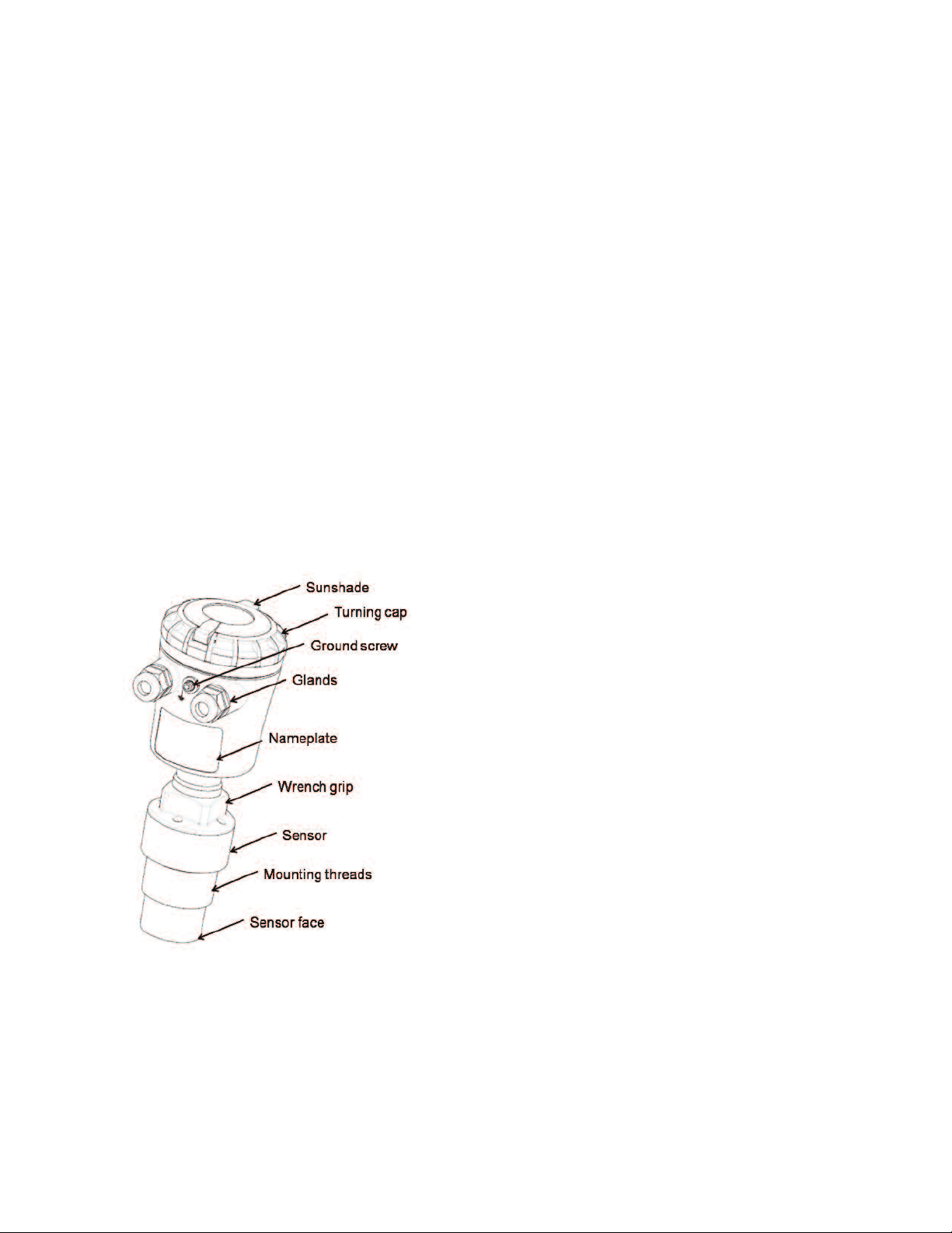
Figure 1: Series ULTM Parts.
Temperature Characteristics
Operational Temperature Range: -4 to 158°F (-20°C to 70°C).
Temperature Sensors: Internal and optional external.
Temperature Compensation: Built-in based on internal sensor, external sensor or
average of the two.
Temperature Display: Internal and external temperature; Instantaneous and
recorded high/low.
Mechanical Specifications
Enclosure Material: Plastic PC/ABS+UV.
Sensor Material: PVDF.
Sealing Rating: IP65/IP67; IP68 - 96 hours at 5.91´ (1.8 m) depth in water.
Mounting Orientation: Vertical.
Mounting Threads: 1.5˝ BSP or 1.5˝ NPT.
Cable Entries: Conduit 1/2˝ NPT.
Weight: 1.95 lb (884.51 g).
*To measure external temperature, contact factory for ULTM-EXT for external
temperature sensor.
Page 2
Page 4
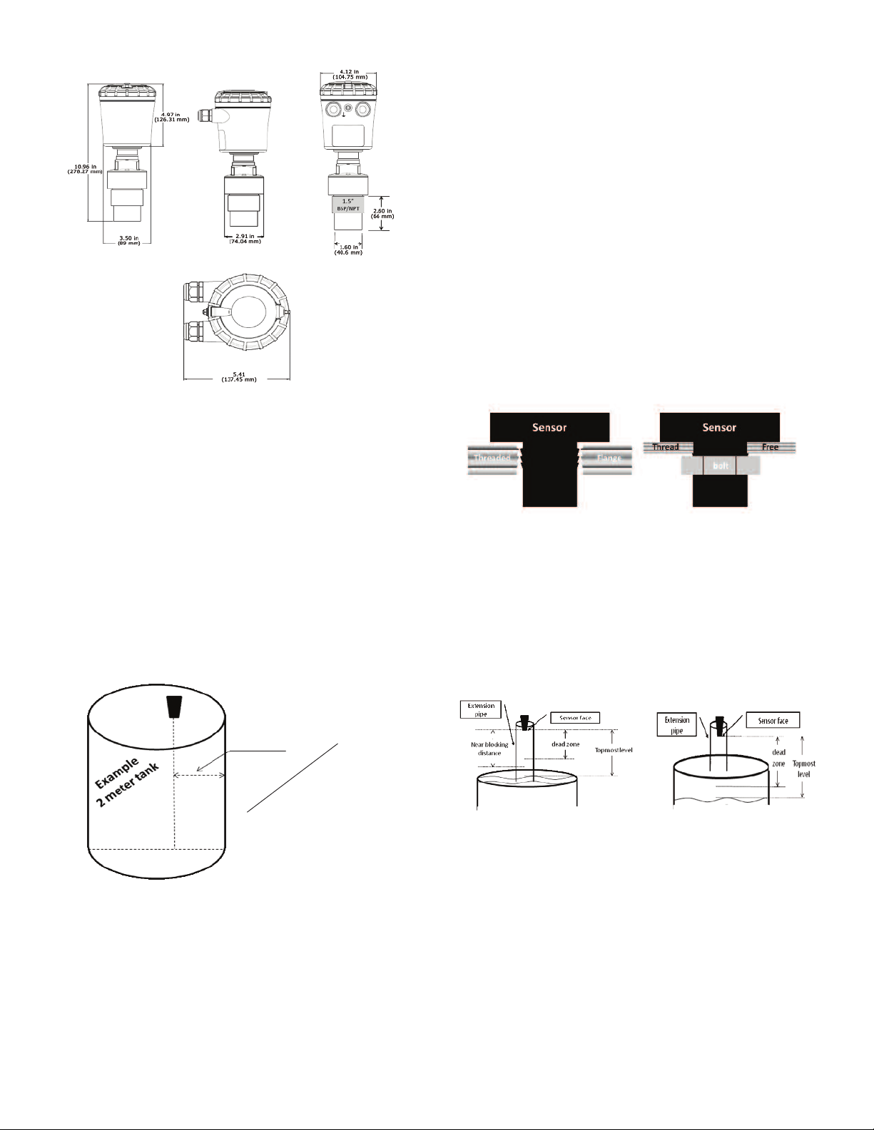
Figure 2: Series ULTM Dimensions.
Chapter 2. Physical and Electrical Installation Guidelines
his chapter is a list of guidelines for proper physical installation of the Series ULTM
T
n tanks, including electrical connections. In the final section of this chapter, there
o
s a short and concise list of instructions–the “Must-Be pamphlet”. Always ensure
i
that the Series ULTM is installed in an area that meets the stated ratings of this
product including temperature and technical specifications.
1. Physical Guidelines
• ULTM systems are installed above the target (e.g. water, fuel) being measured
and should not make contact with the target at any time. Typically, the unit is
installed on top of a tank through a hole on the roof of the
tank. In outdoor applications, the ULTM may be attached to a metal arm
extending above the target attached nearby.
• Series ULTM should be located as far as possible from vertical tank walls and
from other physical obstructions such as filling inlets. Keep a minimum gap of: 12
in (30 cm) plus 4 in (10 cm) for each 3.3 ft (1 m) of measurement range.
• For best results, place the unit away from sources of acoustic noise or
sources of vibrations.
Proper physical installation is accompanied by software setup. Setup includes
•
efining parameters such as tank height, and may include additional parameters
d
uch as Near Blocking Distance (NBD), Far Blocking Distance (FBD), False echo
s
can and more. For additional information refer to the section in Chapter 8
s
reference guide: “Application Dimensions and Constraints” (p.14).
2. Tank Fitting
eries ULTM is equipped with a 1.5˝ BSP or 1.5˝ NPT thread allowing for two fitting
S
ptions: direct fitting in a threaded flange, or fastened with a 1.5˝ BSP / 1.5˝ NPT
o
ut through a thread-free flange.
n
or outdoor installations, use a stable arm and firmly attach the sensor to the arm
F
using a through-hole and threaded nut. Alternatively, it may be possible to attach
the sensor to a threaded hole which is built-in the arm.
lways verify thread compatibility between the Series ULTM and flange or nut. Do
A
ot use excessive force when using threads. Preferably, tighten by hand only. If a
n
rench is used, grip Series ULTM at the wrench grip surfaces only (see Figure 1
w
Series ULTM parts) and exert light force.
3. Dead Zone
Refer to Chapter 8 reference guide: “Application Dimensions and Constraints”
p.14). A gap must be kept between the face of sensor and the topmost level of the
(
arget. This gap must be at least the size of the specified “dead zone”. If the target
t
evel passes the dead zone, measurements may be unpredictable. Therefore, it is
l
recommended to keep a marginal gap between the expected topmost level and the
dead zone border. In the case where the top most level is too close to the tank roof,
an extension pipe is required for the installation of the unit as described below.
Figure 4: Threaded Flange (left) Thread-Free Flange (right).
4. Extension Pipe
Refer to Chapter 8 reference guide: “Application Dimensions and Constraints”
(p.14). An extension pipe is required for installation where the top most target level
is too close to the roof of the tank. In such cases, an extension pipe is installed on
the tank and the sensor is installed on top of the extension pipe at a safe distance
from the top most level of the target. The lower border of the dead zone may fall
inside the tank as seen in the right hand side of the figure below. In this case no
further software settings are required. The lower border of the dead zone may also
fall within the extension pipe as described in the left hand side of the figure below.
In such cases, the Near Blocking Distance (NBD) should be configured in the
software.
r
cm)
e
t
0
3
me
(
m)
2˝
ch
a
c
f 1
e
45
(
per
m)
4˝(10 c
To
17.72˝
l of
a
t
Minimum o
Figure 3: Minimum Gap.
• Series ULTM should be perpendicular to the surface of a liquid target. The angular
displacement should be less than 5° from the vertical axis.
Figure 5: Possible Extension Pipe Fittings.
Page 3
Page 5
typical structure of an extension pipe is shown in Figure 6 below. Closely follow
A
hese guidelines when using an extension pipe:
t
Internal pipe diameter should be at least 3˝ (7.62 cm) wide.
•
The diameter of the hole on the flange or tank should not be smaller than the pipe
•
diameter.
• Pipe length (measured from sensor face) should be no longer than 20˝ (50 cm).
• The pipe should not protrude into the tank.
Pipe should be exactly perpendicular to the surface of the target.
•
Sensor must be located at the center of the pipe.
•
Pipe should have a smooth interior surface.
•
The hole in the flange or tank should have a smooth edge and welding spots must
•
be avoided.
Figure 6: Possible Extension Pipe Fittings.
5. Temperature Considerations and Temperature Sensors
Also refer to Chapter 8 reference guide: “Temperature Sensors, Units and Display”
(p.17).
When using an external temperature sensor, place the sensor at a location that
best represents temperature of the air between the sensor face and the target.
Connect the sensor internally as described in the electrical connection section to
the Thermistor pins. External temperature sensors may be ordered from the
manufacturer or may be purchased independently. Use Thermistor NTC 10 K Ω 5%
(minimum), ULTM-EXT or equivalent.
When using the internal temperature sensor, avoid situations where the Series
ULTM is exposed to different thermal conditions other than its environment, such
as direct sunlight. Direct sunlight may overheat the system and cause
measurement inaccuracies, measurement variations in time, and even failure of the
system in extreme cases. If the Series ULTM is exposed to direct sunlight,
construct a local sunshade (“umbrella”) over the ULTM.
In areas of large temperature variations, take into consideration volume changes of
the target due to temperature expansion.
. Electrical Connections
6
arefully follow these steps when connecting a power supply to the Series ULTM.
C
ower supply must fulfill the proper rating requirements as defined in the
P
pecifications chapter above.
s
6.1 Turn off Series ULTM.
6.2 Turn the ULTM top cap counter-clockwise and expose the electrical
onnections board. Identify the elements as shown in the following figure.
c
Figure 7: Electrical Connections.
GROUND (Pin 4) is a ground and not a common.
*
Pins 1-3 are not used on this device.
*
.3 Insert power cables into the Series ULTM through one of the glands.
6
nsure that high voltage sources or cables are at least 3.28´ (1 m) away from
E
Series ULTM and cables.
Keep the electrical supply lines away from electromagnetic interference
sources.
When inserting a cable through the gland, use round cables with a minimum
iameter of 0.24˝ (6 mm) to ensure that the unit remains sealed to IP67 rating.
d
onnector terminals may be pulled up for easy wire connection and then re-
C
nserted back again.
i
6.4 Connect the power cables to the appropriate terminals.
Note: The Series ULTM operates from a DC power supply of 8 to 33 VDC.
Always make sure that sufficient voltage is present on the Series ULTM power
terminals, disregarding of any voltage drop along the supply lines.
6.5 When using an external temperature sensor or ULTM-EXT, connect the
thermistor to data pins 6 and 7. *Do not wire ULTM-PTS and ULTM-EXT at the
same time.
6.6 When using an external Programmable Timer Switch ULTM-PTS, connect the
switch to pins 6 and 7.
6.7 When using a contact alert, connect short/open between pins 5 and 4 (ground).
See the section about contact alerts in the Chapter 8 reference guide.
6.8 The mini-USB port is a USB device-side supporting virtual COM ports. The port
may be used for firmware upgrades, field monitoring and remote setup. Details
about firmware upgrade are provided in the Chapter 5: Firmware Updates
(p.12).
7. Low Power Mode and Programmable/Timer Switch (PTS), ULTM-PTS
Series ULTM supports low power mode for extended external battery lifetime. This
mode of operation requires the external Programmable Timer Switch (PTS) ULTMPTS to be connected between Series ULTM and battery.
PTS connections:
• First connect the 5-wire cable from the ULTM-PTS to Series ULTM through one
of the glands.
• Connect the Brown (+) wire to the power plus (+) on Series ULTM.
• Connect the Yellow (-) wire to the power minus (-) on Series ULTM.
• Connect the White wire to pin 6 on the electrical port panel (see Figure 7
above).
• Connect the Green wire to pin 7 on the electrical port panel.
• Connect the Blue (ground) wire to the ground port on Series ULTM.
• Then connect the 3-wire cable from the ULTM-PTS to the battery.
• Connect the Brown (+) wire to the battery plus (+).
• Connect the Yellow (-) wire to the battery minus (-).
• Connect the Blue wire to a local ground at or nearby the battery.
ULTM
Figure 8: Programmable Timer Switch Connections.
See PTS software configuration in Chapter 8: Reference Guide.
Page 4
Page 6
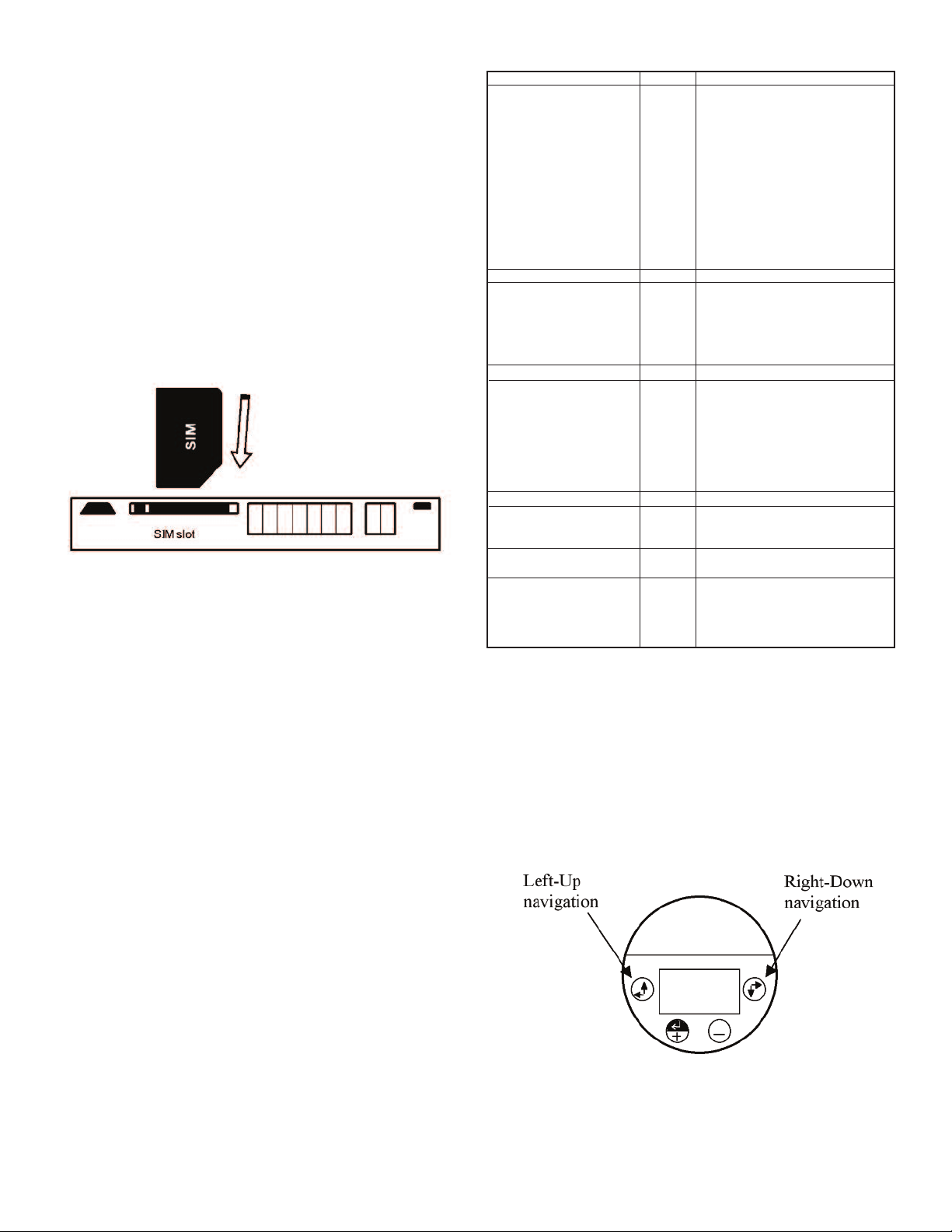
. SIM Card*
8
Mini-SIM card must be inserted in the Series ULTM to allow use of the cellular
A
eature. Never insert or take out a SIM card when Series ULTM power is on. Follow
f
these instructions regarding your SIM card:
8.1 The SIM card must support SMS services with your local cellular operator. You
o not need any voice or browser capabilities in your cellular service.
d
epending on your cellular operator – you might be required to use a USIM
D
ard.
c
.2 Deactivate the SIM PIN code if the PIN code is active before inserting in the
8
ULTM. Deactivation is preformed by inserting the SIM card into a cellular phone
and following the instructions of the phone manufacturer. PIN code
configuration is usually found in your phone Settings – Security Settings – PIN
ode Request or similar.
C
.3 Always test your SIM card before inserting into Series ULTM. Test the SIM card
8
y inserting the card into a cellular phone and sending an SMS. Verify that no
b
PIN code is required, that the proper operator serves the cellular link and that
the SMS reaches its destination.
8.4 Turn off Series ULTM. Turn the Series ULTM top cap counter-clockwise and
expose the electrical connections board. Insert the SIM card into the proper slot
s described in the following figure. The SIM may be pulled out by pressing it
a
ownward again. Insert as shown in Figure 9 below.
d
Figure 9: SIM Card.
8.5 Aim Series ULTM to proper target (e.g. floor), turn on Series ULTM and closely
observe the lower status line on the display (status lines are explained in the
Operating Instructions Chapter 3- Measurement Screen sub-chapter).
You should observe the report “GSM Initializing” for 30 to 60 seconds. Then you
should observe several additional status reports including “GSM Active”. This
indicates proper SIM card operation.
*Series ULTM only supports AT&T and T-Mobile mini-SIM cards. Make sure unit will
work with carrier.
. Must Be Pamphlet
9
. Choosing Location
1
istance to Tank Walls
D
Flange
Acoustic Noises
lectrical Interference
E
ank Installation
T
Sensor
xternal Thermistor
E
. Handling Dead Zone
2
xtension Pipes (1)
E
Extension Pipes (2)
xtension Pipes (3)
E
. Power Source
3
Voltage
Battery (Internal/External)
Ripple and Noise
ype
T
SB Power Source
U
4. Cellular Communications
SIM Card with SMS Service
Destination Phone Number
SMS Alerts
5. Measurement
Configuration
Full/Empty, Level/Distance
Filling Rate
False Echo Scan
Near Blocking Distance (NBD)
Chapter 3. Operating Instructions
This chapter describes the keypad and display of the Series ULTM. The keypad
and display add the following functionality to Series ULTM:
• Viewing measurement results and viewing information related to the system
• Configuring Series ULTM
This chapter focuses on the structure and operation of the keypad and display.
Configuration of the system via a PC is described in following chapters. Expose the
keypad by turning the cap counterclockwise all the way.
UST BE
M
UST BE
M
MUST BE
MUST BE
UST BE
M
UST BE
M
MUST BE
UST BE
M
MUST BE
MUST BE
UST BE
M
UST BE
M
MUST BE
UST BE
M
MUST BE
MUST BE
UST BE
M
MUST BE
MUST BE
MUST BE
MUST BE
MUST BE
t least 11.81˝ (30 cm) from walls
A
3.94/39.37˝ (+10 cm /1 m) range.
+
ixed on a horizontal surface.
F
Far away from acoustic noises and
vibrations.
Shielded away from power and sensor
ables.
c
ar away from tank inlets, outlets,
F
hysical obstacles.
p
xactly perpendicular to the surface of
E
the target.
In shaded location, attached to the tank
body.
f at least 3˝ (7.62 cm) internal
O
iameter and 5.91˝ (15 cm) above
d
target (from sensor face).
With completely smooth interior surface.
Installed with a flange/not protruding
into the tank.
t least 8 VDC on unit terminals.
A
ated higher than 8 VDC due to
R
voltage drop.
Not exceeding 100 mV.
referably regulated switching power
P
upply.
s
Accompanied by power source for field
operations.
Inserted in the SIM card slot.
et and formatted correctly.
S
Defined using correct limits.
Configured correctly.
Defined (consider the application).
Executed when the tank is empty.
Set up in flange and extension pipe
installations.
1. Keypad
1.1 Navigation Keys
Use the navigation keys to scroll through the display.
Figure 10: Navigation Keys.
Page 5
Page 7

.2 Execution Keys
1
se the execution keys to change a digit or to execute a command (Back, Next or
U
ub-menu).
S
o change a digit: navigate to the digit and press the plus (+) key or the minus (-)
T
key.
To execute a command: navigate to the command and press the enter (+) key.
Remember–some changes are saved only after returning to the measurement
creen. If you shut down Series ULTM before you return to the measurement
s
creen, your changes may be lost.
s
igure 11: Execution Keys.
F
2. Navigation Through Menus
Series ULTM supports two menu styles that are used throughout the setup
perations and are described below. False echo scan employs a third menu style
o
nd is described in the relevant section below.
a
2.1 Sub-Menu Style
The Sub-Menu style presents a list of vertical choices. An arrow may appear on the
right hand side of the screen if additional items can be reached when scrolling
down. The scrolling is cyclic, meaning that when you reach the last (first) item, the
next step will lead you to the first (last) item. Scroll up or down, using the navigation
keys, to your selected choice and press Enter (+). This action will lead you to the
next sub-menu.
The last item in the list of choices is **back**. Select **back** to return to the
previous menu. The previous menu will be displayed such that your last selection
will appear first on the menu. For example:
fter pressing Next, ULTM will check the validity of your numerical entry. If your
A
ntry is outside the acceptable boundaries, an ILLEGAL VALUE screen will be
e
resented. You need to press any key to return to the previous screen. A default
p
alue will replace your wrong entry. If so needed, modify the numerical entry and
v
press Next again.
The top line presents the current measurement information.
.3. Menu and Sub-Menu Organization
2
LTM menus and submenus are organized in a tree-like format. The organization
U
s described in the following figure:
i
igure 14: Menu and Sub-Menu Organization.
F
3 Measurement Screen
±XX
setup
°
T
dB
ID
Figure 12: Sub Menu Screens.
2.2 Numeric Menu Style
The numeric menu style presents you with a multi-digit number which may be
modified. Navigate to each digit and modify the digit as required by using the plus
(+) or minus (-) keys.
When you are done with all digits, select Next to move on. Select Back to ignore
the changes and return to the previous sub-menu. Modifications will become
permanent (survive a reset) when you navigate back to the measurement screen.
For example:
By repeatedly pressing the Right-Down navigation key, you will follow this route:
Figure 13: Numeric Menu.
X1 → X2 → X3 → X4 → Next → Back → X1→ X2 →…
Conversely, by repeatedly pressing the Left-Up navigation key, you will follow the
opposite route.
Figure 15: Measurement Screen.
3.1 Status Reports
Status reports appear beneath the measurement result. On the first line, reports
related to ultrasonic monitoring issues are presented. On the next line, cellular
communication related reports are displayed. Ultrasonic reports include messages
such as: FULL LEVEL, EMPTY LEVEL, ECHO SEARCH, THEFT, START FILL,
END FILL and others. Cellular related reports include messages such as SMS
SENT, SMS ACTIVE, REGISTRATION FAILED and more.
The bottom line on the screen presents a toolbar with choices. Navigate through
the toolbar and select an action or report. ULTM halts any operations (including
measurements) during navigation. ULTM will automatically resume operations 30
seconds after last key has been pressed.
3.2 Contrast
Press the plus (+) or minus (-) keys to change visual contrast of the display.
3.3 Main Menu / Setup
Navigate to setup and press Enter (+) to configure ULTM. The actual configuration
process is explained in a following chapter.
Page 6
Page 8

.4 Temperature Readings
3
avigate to the T° symbol on the toolbar and press Enter (+). The following table
N
ill be displayed:
w
he table is explained in the Chapter 8 reference guide section: “Temperature
T
Sensors, Units and Display” (p.17). Press reset to reset recorded high / low
temperatures, or press done to return to the measurement screen.
ow
High
31.0
32
L
6
2
23.3
Done
Cur
Sens:
29.5
Int
29.4
xt
E
eset
R
igure 16: Temperature Readings.
F
3.5 Ultrasonic Echo Conditions
avigate to the dB symbol and press enter (+). You will be presented with the
N
easured echo amplitude and the maximum amplitude available. The amplitudes
m
re presented in dB relative to a system threshold amplitude. Echo amplitude
a
should be above threshold amplitude for reliable measurement. Echo strength
between 3 dB and 8 dB (maximum) is reliable. Echo amplitude refers to the echo
measured just prior to navigating through the toolbar. Press done to return to the
measurement screen.
.6 Product Identification Details
3
rom the measurement screen, navigate to the ID symbol on the toolbar and press
F
Enter (+). Product information will be displayed: serial number and part number.
Press Back to return to the measurement screen or navigate to one of the options:
Software Information (SW), Hardware Information (HW), or Manufacturing Date
Information (Date). SW screen will display firmware versions of the embedded
pplication and of the embedded boot-loader. Press Back to return to the previous
a
enu. HW screen will display product information regarding sensor type and model
m
ype. Press Back to return to the previous menu. Date screen will present the date
t
of manufacturing. Press Back to return to the previous menu.
4. Quick Setup
Set ULTM for operation by a quick 7-step wizard-driven procedure using the basic
menu option.
Note: Configuration using the display and keypad supports metric units only. For
English units, use the PC configuration method as described in the Chapter 5
describing Configuration with a PC (p.9).
A. Turn on ULTM and wait for the measurement screen to show up. Navigate
through the toolbar and select setup.
B. Scroll and select Basic Setup from the Main Menu.
C. Scroll and select application (Low power or High power). For additional details
about the application type refer to the reference guide under Chapter 8:
“Application Type” (p.15).
D. Determine distance to empty level. For additional details about the empty level,
see the reference guide section Chapter 8: “Application Dimensions and
Constraints” (p.14). When you are done press Done.
E. Determine distance to the full level. For additional details about the full level, see
the reference guide section Chapter 8: “Application Dimensions and
Constraints” (p.14). When you are done press Done.
F. Scroll and select value to display. For additional details about value-to-display,
see the reference guide section: Chapter 8: “Distance Units and Value to
Display” (p.15).
G. Skip or perform false echo search. See the section “False Echo Scan” in
Chapter 8, the reference guide chapter (p.16).
5. False Echo Scan
Perform a false echo scan when obstructions are nearby the target or sensor.
Preferably, false echo scan should be performed when the tank is empty. If you
choose to perform false echo scan, wait for about a minute and then you will be
presented with a list of echoes.
elect an echo, scroll to that echo and press Enter (+) again. If you choose to
s
erform false echo scan a second time, new echoes which were not identified
p
uring the first scan will be reported as “new”.
d
The ULTM is now ready for measurements.
Parameters which are not determined during quick setup procedure will take their
efault value and may be modified later using the Advanced Setup menu.
d
ote: Always verify then re-verify that your basic settings are correct including
N
istance to empty level, distance to full level, level or distance choice. Most wrong
d
eadings originate from incorrect basic setup.
r
. Advanced Settings
6
LTM supports a set of advanced settings. These settings are classified under
U
hree categories: GSM, Algorithm and Device state. The following items may be
t
modified under each category:
ub Menu Items
ategory
C
SM
G
lgorithm
A
Device state
To execute any of the advanced settings, follow these steps: Turn ON ULTM and
wait for the Measurement screen to show up. Navigate and select Setup. Then
scroll and select Advanced Setup from the Main Menu. Now select the required
category (GSM, Algorithm or Device state) and follow the screen instructions.
When done, scroll and press **back** to return to the Main Menu, then scroll and
select the measurement display.
Each item may either present a selection of sub-items to choose from or may
require entry of a numeric field.
If you are not sure what sub-item to select or how the numeric field should be
modified, leave the default values as is.
7. Settings Available in PC Configuration Only
Some advanced settings are available in a PC configuration only and cannot be
configured with the display/keypad. These settings are defined in the following
table.
Setting
Units
Value to Display
USB Monitoring
Tank Shape and Dimensions
Theft and Refill Alerts for Volume
Programmable Timer Switch
S
estination phone number
D
eporting interval
R
Full and empty alerts
Theft/Refill alerts active
once value is set for rate
nd level
a
ar blocking distance
F
Near blocking distance
Filling rate
Temperature units
Reset to defaults
Operating hours
See Section in Chapter 8
Reference Guide…
Destination Phone
“
umber”
N
GSM reporting Interval”
“
“Theft Alerts”
“Refill Alerts”
Application Dimensions &
“
Constraints”
“Application Dimensions &
Constraints”
“Filling Rate”
“Temperature Sensors,
Units and Display”
“Reset and Operating
Hours”
“Reset and Operating
Hours”
Options
Meter, feet, liter, gallon
Volume
Enable and disable
Cubic, cylindrical
Level and duration
PC Command
UNT
VAL
ENDT, DSDT
CUB, CYLV, CYLH
ATF, ARF
LPST
Notes
1-Enable
0-Disable
-Enable
1
-Disable
0
Figure 17: False Echo Scan Screen.
Scroll through the listed echoes and press Enter (+) on each echo you would like
to ignore during measurement. Each such echo will be designated by a √ sign. The
number of selected echoes is presented on the top-right edge of the screen. Press
Save to store your selection and Next to proceed to the next sub-menu. To un-
Page 7
Page 9

hapter 4. Configuration with a PC
C
. Introduction
1
LTM is pre-configured at the factory to default settings. See reference guide
U
section in Chapter 8: “Default Values” (p.15). The system is delivered to the user
ready for operation. Some configuration parameters should be re-configured by the
user for proper field application. ULTM can be configured by a simple PC tool.
onfiguration by PC may be used in lieu of configuring with the integral keypad and
C
isplay. PC configuration provides the user with the full set of configuration items.
d
urthermore, configuration by PC allows the user to clone fielded ULTM systems.
F
For this cloning process, the user is required to prepare one text file and download
that file into all relevant ULTM systems. Once this configuration file is prepared, the
downloading process takes a few seconds and makes redundant any manual
eypad based operation.
k
ection 2 below begins by demonstrating a sample configuration text file.
S
Section 3 handles the downloading operation. The download process involves use
of a standard Windows application – HyperTerminal. The setup of HyperTerminal is
explained in the second section, and parts of it may be skipped by those who are
lready familiar with this tool. Section 4 presents possible responses from
a
LTM–whether good or erroneous responses. Section 5 is a list of all configuration
U
tems. Section 6 provides some configuration file example.
i
2. Preparing a Configuration Text File
he next example looks fine but the Enter button was not pressed. This will cause
T
n error.
a
2.2 Multi Value Commands
ome configuration items are assembled from two values or more. For example,
S
he dimensions of a vertical cylindrical tank (prefix CYLV) are height and diameter.
t
hese two values are both included with a comma between the two values. The
T
next figure illustrates the use of the comma.
2.1 A Simple Sample File
he following text file was created using Windows Notepad application and
T
emonstrates the essence of the configuration file:
d
Digest:
• The first line resets ULTM to its default values.
• The second line instructs ULTM to set its EMPTY LEVEL to a distance of 6.0
meters.
• The third line instructs ULTM to set its FULL LEVEL to a distance of 0.70 meters.
If you are unfamiliar with terms such as empty level or full level, read reference
guide section Chapter 8: “Application Dimensions and Constraints” (p.14). Next is
a slightly more complex configuration file:
Digest:
• The first line instructs ULTM to set its EMPTY LEVEL to a distance of
18 ft (5.5 m).
• The second line instructs ULTM to set its FULL LEVEL to a distance of
1.5 ft (0.45 m).
• The third line instructs ULTM to set up the destination phone number to
+49-1-1234567 (10 digits only).
• The forth and last line instructs ULTM to set up SMS interval time to 1800
seconds.
• Each instruction is implemented as a specific command such as EMP or FUL.
he third line instructs ULTM to set the tank as a vertical cylindrical tank with height
T
f 4.5 meter and diameter of 3.00 meters. The last item instructs ULTM to display
o
olume results (rather then level or distance). The comma should always separate
v
between values.
3. Download Operation
3.1 General Procedure
ULTM can be configured by downloading the text configuration file from your PC
into ULTM. The previous chapter described the making of the configuration file.
This chapter describes the download procedure. The download process can be
preformed using HyperTerminal – a Microsoft
most operating systems such as Windows XP
®
standard application which is part of
®
.
Prior to using the HyperTerminal, you must connect ULTM to the PC and install a
USB-Serial driver on the PC. You can do that by following the instructions in the
Chapter 8: “USB driver installation on a PC” (p.13).
You should find out the COM port number that ULTM is using on the PC. ULTM
must be in the measurement screen during download procedure. Two PC
applications trying to access ULTM will conflict with each other. Avoid having two
such applications running at the same time.
3.2 Launching and Setting Up HyperTerminal
This section assumes you are using Windows XP
®
. Similar procedures apply to
other operating systems.
3.2.1 Go to Start Menu and then Open Programs.
3.2.2 Open Accessories, then Open Communications then Open HyperTerminal.
3.2.3 Press NO when asked about “default telnet program”.
3.2.4 When prompt for a name, choose any name and press OK.
3.2.5 In the next window “Connect to”, select the COM port that you intend to use
for ULTM. This part is described in the next figure:
Notes:
• Each line begins, and ends, with a $ sign.
• All commands are made of capital letters.
• Each command is immediately adjacent to the first $ sign.
• There is a blank between the command and the related parameter.
• There is a blank between the parameter and the ending $ sign.
• Do not forget to press Enter after the last line.
Windows® and Windows® Xp are registered trademarks of Microsoft Corporation
Page 8
Page 10

.2.6 In the next window “COM properties - port settings”, set the parameters as
3
escribed below:
d
.2.10 Press OK and then OK again – you are all set to configure ULTM.
3
.3 Downloading a Configuration File
3
.3.1 From the HyperTerminal screen select transfer (top right side tab) and then
3
select “Send File”.
3.3.2 Browse to the directory where you stored the configuration text file (the one
you prepared in the previous section) and select that file. Double click on the
ile to transmit it.
f
.3.3 Alternatively, you can key each configuration item line by line directly from the
3
yperTerminal screen. As a quick test of this configuration, key the following
H
ommand:
c
$VAL 1 $
Watch ULTM integral display and verify that measured data is level.
Now key the following command:
VAL 2 $
$
atch ULTM integral display and verify that measured data is distance.
W
3.2.7 Now you should see the HyperTerminal screen:
.2.8 Select the File tab (on the top left side) and choose Properties, then Settings,
3
nd set the parameters as described below:
a
3.2.9 Now press on ASCII setup (bottom right side) and set the parameters as
described below:
4. Responses from Series ULTM
4.1 Good Response
ULTM should reply with an OK response to each configuration item:
4.2 Erroneous Responses
ULTM will reply with an ERROR or NOTE response to a wrong configuration item.
For example:
The ERROR or NOTE response will be followed by the causing item (in this case
EMP) and is accompanied by an error number (5 in this case). Possible error codes
are listed in the following table:
Error Code
1, 2
3
4
5
6
7
8
9
4.3 Communication Errors
The erroneous responses described indicate that the link between PC and ULTM
is operating fine and that the commands are of wrong nature.
Most probable cause
Configuration item is too long
$ sign is probably missing
Wrong command name or command not adjacent to $ sign
Value is exceeds upper legal limit
Value is below lower legal limit
Value is illegal
(NOTE) Command was already sent
(NOTE) Value is below minimum value and redefined to
minimum value
Especially note the “Line Delay” and the “Character Delay”, which are not the
default values of HyperTerminal.
Note: When using the USB port for local serial data monitoring (see appropriate
chapter), you should return to the default values of the screen above and
specifically uncheck “Append Line Feeds to Incoming Line Ends”. And vice verse,
if you revert to configuration of ULTM through the USB interface, make sure to set
the parameters of the screen above correctly.
If no responses are received from ULTM, or if the responses carry unfamiliar
characters, the communication link between the PC and ULTM is not performing.
In this case, you need to check the physical cabling, verify the HyperTerminal
settings and then restart this application again.
5. Reference Guide for Configuration from a PC
5.1 List of Configuration Items
The following conventions apply for the list of commands. These conventions refer
to the values allowed for each parameter.
5.1.1 Range of Number Values
A range of number values is presented with a hyphen. For example: 0.150-8.000.
This entry means that the value may be any number between 0.150 and 8.000.
Always use the decimal point. The number of decimal digits may be less than three.
Page 9
Page 11

.1.2 Range of Whole Number Values
5
range of whole number values is presented with a hyphen. For example: 1 - 99.
A
his entry means that the value may be any whole number between 1 and 99.
T
5.1.3 Several Distinct Values
When a parameter can be one of a few distinct values, each value is listed on
separate lines with an explanation. For example:
ommand
C
AL (3)
V
Command Description
alue to display
V
Possible Values
1
2
3
Value Description
Level
Distance
olume (set also tank
V
hape)
s
5.2 List for Metric Unit System
tem
I
PP (
A
EMP (
FUL (
VAL (
NT (
U
UNT (
FBD (
NBD (
RAT (
TMP (
SNS (
RSD (
RSC (
RST (
GMAN
ENDT (
DSDT (
CUB (
CYLV (
CYLV (
CYLH (
CYLH (
TEL1 (9)
TEL1 (
SMST (
AFE (
ATF (
ATF (
ARF (
ARF (
Description
1
pplication type
A
)
2
mpty level
E
)
2
Full level
)
3
Value to display
)
3
Units for VAL=1,2,4,5
)
3
Units for VAL=3,6
)
2
ar blocking distance
F
)
2
Near blocking distance
)
4
Filling (tracking) rate
)
5
Temperature unit system
)
5
Temperature sensor
)
6
Reset to factory defaults
)
6
Reset hour counter
)
6
Restart ULTM
)
Get manufacturer data
8
Enable USB monitoring
)
8
Disable USB monitoring
)
7
Cubic tank
)
7
Vertical cylindrical tank
)
7
Vertical cylindrical tank
)
with concave bottom
7
Horizontal cylindrical tank
)
with curved sides
7
Horizontal cylindrical tank
)
with flat sides
9
Cell-phone destination
)
10
SMS periodic interval
)
11
Full / Empty alerts
)
12
Theft alert for VAL=1,2,4,5
)
12
Theft alerts for VAL=3,6
)
13
Refill alerts for
)
VAL=1,2,4,5
13
Refill alerts for VAL=3,6
)
ossible values
P
Basic Setup (Metric)
0
1
.150 – 8.000
0
.150 – 8.000
0
1
2
3
4
5
6
1
2
3
4
Advanced Setup (Metric)
0.150 – 8.000
0.150 – 8.000
0
1
2
3
3
4
0
1
2
Resetting and ID Options (Metric)
None
None
None
None
None
None
Tank Shapes and Dimensions (Metric)
0.00-99.99, 0.00-99.99
0.00-99.99, 0.00-99.99, 0
0.00-99.99, 0.00-99.99,
0.00-99.99
0.000-99.99, 0.000-99.99,
0.001-99.99
0.000-99.99, 0.000-99.99, 0
XXXXXXXXXXXXXX
Communication and Alert Items (Metric)
XXXXXXXXXXXXXX
0
180-3999999
0
1
0, 0
4-99, 0
0, 0
4-99, 0
0, 5-500
0, 0, 1
4-99, 0, 1-3
0, 0, 1
4-99, 0, 1-3
0, 3-500, 1-3
alue description
V
High power
Low power
istance in meters
D
istance in meters
D
Level
Distance
Volume (set also tank shape)
% Level
Distance
%
% Volume (set also tank shape)
Meter
Feet (see list for English units)
iter
L
S Gallons (see list for English units)
U
Distance in meters
Distance in meters
1 meter / minute
2 meter / minute
5 meter / minute
10 meter / minute
Celsius
Fahrenheit
Internal sensor
External sensor
Average of both
Response is serial number and manufacturer date: dd-mm-yyyy
Width and depth (horizontal dimensions) in meter
Height of tank = EMP value in meter
Diameter of tank in meter
Height of tank = EMP value in meter
Diameter of tank in meter
Breadth of bottom in meter
Length, diameter and curved breadth in meter.
Length and diameter in meter
Exactly 14 digits where X is any digit 0-9 or *,+,No periodic reports
Interval in seconds
No alerts
Alerts activate
No alerts
Normal consumption in mm/minute
No alerts
Normal consumption in mm/minute
Normal consumption in liter/minute
No alerts
Minimal alerted level change in mm and minimum fill duration in minutes
No alerts
Minimal alerted level change in mm and minimum fill duration in minutes
Minimal alerted level change in liters and minimum fill duration in minutes
.1.4 Two Parameters for the Same Command
5
n entry such as 1-9999, 0.150-8.000 means that the command is made of two
A
arameters and requires two values. A comma separates the two values. In this
p
xample the first value may be any whole number between 1 and 9999. The
e
second value may be any number between 0.150 and 8.000.
5.1.5 Two Parameters with One Parameter Fixed
n entry such as 1-99, 0 means that the configuration item requires two values, but
A
he second value must be 0. The first value in this example may be any whole
t
umber between 1 and 99.
n
The user may select one of two units systems: Metric or English. A separate
command list is provided below for each unit system. The user can select their
preferred unit system with the UNT command.
Page 10
Page 12

4
1
PST (
L
Low power timer
)
1-99999, 0.150 – 8.000,
1-99999, 0.150 – 8.000, 0-1, 0-1
ll notes are explained in section 5.4.
A
.3 List for English Unit System
5
Item
PP (
A
MP (
E
FUL (
VAL (
UNT (
UNT (
FBD (
BD (
N
AT (
R
TMP (
SNS (
RSD (
RSC (
RST (
GMAN
ENDT (
DSDT (
CUB (
CYLV (
CYLV (
Description
1
pplication type
A
)
2
mpty level
E
)
2
Full level
)
3
Value to display
)
3
nits for VAL=1,2,4,5
U
)
3
Units for VAL=3,6
)
2
Far blocking distance
)
2
ear blocking distance
N
)
4
illing (tracking) rate
F
)
5
Temperature unit system
)
5
Temperature sensor
)
6
Reset to factory defaults
)
6
Reset hour counter
)
6
Restart ULTM
)
Get manufacturer data
8
Enable USB monitoring
)
8
Disable USB monitoring
)
7
Cubic tank
)
7
Vertical cylindrical tank
)
7
Vertical cylindrical tank
)
with concave bottom
7
CYLH (
CYLH (
Horizontal cylindrical tank
)
with curved sides
7
Horizontal cylindrical tank
)
with flat sides
TEL1 (9)
9
TEL1 (
SMST (
AFE (
ATF (
ATF (
ARF (
Cell-phone destination
)
10
SMS periodic interval
)
11
Full / Empty alerts
)
12
Theft alert for VAL=1,2,4,5
)
12
Theft alerts for VAL=3,6
)
13
Refill alerts for
)
VAL=1,2,4,5
13
ARF (
Refill alerts for VAL=3,6
)
ommunication and Alert Items (Metric)
C
ossible values
P
Basic Setup (English)
0
1
0.50 – 26.00
0.50 – 26.00
1
2
3
4
5
6
1
2
3
4
Advanced Setup (English)
0.50 – 26.00
0.50 – 26.00
0
1
2
3
3
4
0
1
2
Resetting and ID Options (English)
None
None
None
None
None
None
Tank Shapes and Dimensions (English)
0.00-300.00, 0.00-300.00
0.00-300.00, 0.00-300.00, 0
0.00-300.00, 0.00-300.00,
0.01-300.00
0.000-99.99, 0.000-99.99,
0.001-99.99
0.000-99.99, 0.000-99.99, 0
XXXXXXXXXXXXXX
Communication and Alert Items (English)
XXXXXXXXXXXXXX
0
180-3999999
0
1
0, 0
0.16-4.00, 0
0, 0
0.16-4.00, 0
0, 1.4-26.00
0, 0, 1
0.16-4.00, 0, 1-3
0, 0, 1
0.16-4.00, 0, 1-3
0, 0.8-26, 1-3
Long standby interval in minutes
Distance to low level in meters
Short standby interval in minutes
istance to high level in meters
D
isable (0) or enable (1)
D
- No SMS are sent when in the “Long Standby Mode”. 1 – SMS are sent
0
hen in “Long Standby Mode”.
w
alue description
V
igh power
H
Low power
Distance in feet
Distance in feet
evel
L
istance
D
olume (set also tank shape)
V
% Level
% Distance
% Volume (set also tank shape)
Meter (see list for metric units)
eet
F
iter (see list for metric units)
L
allons (US)
G
Distance in feet
Distance in feet
3 feet / minute
feet / minute
6
5 feet / minute
1
30 feet / minute
Celsius
Fahrenheit
Internal sensor
External sensor
Average of both
Response is serial number and manufacturer date: dd-mm-yyyy
Width and depth (horizontal dimensions) in feet
Height of tank = EMP value in feet
Diameter of tank in feet
Height of tank = EMP value in feet
Diameter of tank in feet
Breadth of bottom in feet
Length, diameter and curved breadth in feet
Length and diameter in feet
Exactly 14 digits where X is any digit 0-9 or *,+,No periodic reports
Interval in seconds
No alerts
Alerts activate
No alerts
Normal consumption in inch/minute
No alerts
Normal consumption in inch/minute
Normal consumption in gallon/minute
No alerts
Minimal alerted level change in inch and minimum fill duration in minutes
No alerts
Minimal alerted level change in inch and minimum fill duration in minutes
Minimal alerted level change in gallons and minimum fill duration in minutes
Page 11
Page 13

4
1
PST (
L
Low power timer
)
1-99999, 0.50 – 26.00,
1-99999, 0.50 – 26.00, 0-1, 0-1
ll notes are explained in sections 5.4.
A
ommunication and Alert Items (English)
C
Long standby interval in minutes
Distance to low level in feet
Short standby interval in minutes
istance to high level in feet
D
isable (0) or enable (1)
D
- No SMS are sent when in the “Long Standby Mode”. 1 – SMS are sent
0
hen in “Long Standby Mode”.
w
Perform firmware upgrade only when authorized to do so by the manufacturer.
•
5.4 Notes
ote Number
N
(1)
(2)
(3)
4)
(
5)
(
6)
(
(7)
(8)
(9)
(10)
11)
(
12)
(
13)
(
(14)
15)
(
16)
(
. Useful Examples
6
See Detailed Information in Reference Guide Chapter…
ection: “Application Type”
S
ection: “Application Dimensions and Constraints”
S
ection: “Distance Units and Value to Display“
S
ection: “Filling Rate”
S
Section: “Temperature Sensors, Units and Temperature Display”
Section: “Reset and Operating Hours”
ection: “Volume Measurement”
S
ee Chapter 6: “Serial Data Monitoring”
S
ection: “Destination Phone Number”
S
Section: “GSM Reporting Interval”
Section: “Full and Empty Alerts”
Section: “Refill Alerts”
Section: “Theft Alerts”
Section: “PTS Configuration”
Section: “Trigger Alerts”
Section: “GPRS Architecture”
6.1 Basic Setup
$RSD $
$APP 0 $
$EMP 8.0 $
$FUL 0.15 $
$VAL 1 $
Reset to factory defaults
Application is high power
Distance to empty level is 8 meter
Distance to full level is 0.15 meter
Value to display is level
6.1 Advanced Setup
$DATA D $
$VAL 1 $
$FBD 8.0 $
$NBD 0.4 $
$RAT 3 $
$TMP 3 $
$SNS 0 $
$TEL1 +49-25-4678911- $
$SMST 1800 $
$AFE 1 $
$ATF 4, 0 $
$ARF 8, 0, 2 $
$CYLV 5.0, 2.0 $
SMS messaging
Value to display is level
Far blocking distance is 8 meters
Near blocking distance is 0.4 meters
Tracking rate is 10 meters per minute
Temperature unit is Celsius
Temperature sensor is the internal
Cell-phone destination is +49-25-4678911
Interval between periodic SMS messages is 1800
second
Empty and full event alerts are on
Theft alerts ON and for rate above 4 mm per minute
(for VAL=1)
Refill alerts ON for minimum refill of 8 mm during 2
minutes
Tank is vertical cylindrical, height 5 m and diameter 2
m
• While upgrading ULTM, record your steps and also record any messages that
appear on-screen. This will aid in troubleshooting a defective upgrade process.
• Most stored settings will usually not be lost when upgrading the firmware.
Use only the updated firmware provided by the manufacturer or re-seller.
•
. You Will Need
2
(A) PC with minimum requirements: Windows XP
7/16 /bit, CD drive, USB port, and administrator rights. The firmware upgrade
tool was also tested on Windows
®
7/32 bit.
®
Service Pack 2 or Windows
®
(B) ULTM Installation CD.
C) New ULTM firmware which is authorized for upgrading your ULTM.
(
. Installation of Firmware Upgrade Tool and USB Driver
3
(A) Insert the installation CD, select and run Setup.exe in the main directory of the
CD.
(B) Follow the on-screen instructions. When prompted for an installation directory,
keep the default installation directory:
“c:\program files\solidat\ULTMFirmwareUpgradeTool” or choose another
(
irectory).
d
C) When complete, check for new icon on your desktop and new program entry in
(
the programs list.
(D) Install ULTM USB driver by following instructions in Chapter 7: “USB driver
installation on a PC”.
4. Upgrade Procedure
(A) Copy the new ULTM firmware (e.g. xyz.bin) to a directory of your choice.
(B) Run ULTM Firmware Upgrade Tool by clicking on the proper desktop icon.
(C) Wait until the proper COM port is identified (the port connected with ULTM) then
press OK on the pop-up window.
Verify that current firmware version is displayed on the top line.
(D) Click on the
“…” button, browse and select the new firmware (e.g. xyz.bin).
When the new name appears on the windows, you can press the “upgrade new
firmware” button. Follow the progress and instructions on-screen. After some
time, ULTM display will be turned off – this is normal.
During the upgrade, you will see a progressive bar on the window as follows:
$LPST 60, 6, 10, 3, 1 $
Low power timer is ON: Low level sleep time of 60
minutes when the distance to target above emptylevel and longer than 6 meters. High level sleep time
is 10 minutes and occurs when distance to target is
more than 3 meters, but still less than 6 meters.
ULTM will operate continuously when the distance to
target is less than 3 meters.
Note: Always verify then re-verify that your basic settings are correct including
distance to empty level, distance to full level, level or distance choice. Most wrong
readings originate from incorrect setup.
Chapter 5. Firmware Updates
1. Introduction
ULTM firmware can be upgraded in the field. The upgrade procedure takes less
than 5 minutes, but should be done carefully to avoid damage to the system. This
feature is useful for adding new features to your ULTM system and for fixing
bugs.
If you do not see the bar starting, or if the bar has stopped moving – just wait! If
Be patient!
you disconnect the ULTM while in the middle of the upgrade process, the internal
software may be impaired and may require returning to the factory. If the bar has
not started or has stopped, wait for at least 10 minutes before reconnecting and
restarting the process.
Page 12
Page 14

E) Wait for the upgrade process to complete. The process is complete when you
(
ee the following window:
s
ow click OK and restart ULTM.
N
. Troubleshooting the Firmware Upgrade Process
5
ecommendation
Symptom
R
Installing Upgrade Tool
nstall .NET Framework on you PC (2.0 or
Installation of the upgrade tool
halts due to .NET Framework
issing.
m
Installation of the upgrade tool
halts due to user permissions
I
above). See
http://www.microsoft.com/downloads/details.as
x?familyid=0856eacb-4362-4b0d-8edd-
p
ab15c5e04f5&displaylang=en
a
erify that you are a local administrator on the
V
PC.
Upgrading the Firmware
1) Make sure ULTM is turned on. Disconnect
COM port is not found
r Current firmware version is
o
ot displayed
n
(
nd then connect again the USB cable.
a
(2) Select the Communication tab. Try
automatic port selection then try manual
port selection.
(3) Shut off the Upgrade Tool, then verify with
he Windows
t
®
ask Manager that a ULTM
T
process is not running. Run the Upgrade
Tool again.
Upgrade process has halted
Wait for 10 minutes. Restart the application.
Restart your PC and try again.
ULTM display stays blank after
Restart your PC and try again.
installation and restart
Chapter 6. Serial Data Monitoring
1. Introduction
ULTM may be monitored locally. ULTM may be configured to send information to
a PC over the USB interface and that information may be viewed with a
HyperTerminal application. This feature is useful for field monitoring and for
debugging purposes.
E) Information may be simply viewed or gathered into a text file by using the
(
ransfer/Capture Text tab of HyperTerminal. You can define this file as .txt or
T
csv. You can also define the file as txt and later rename it to .csv. A .csv file
.
an then be conveniently viewed with an excel application.
c
Other data logging programs include Log & Forward and SMS Management Center
found on the ULTM software CD. These programs use SMS messages sent directly
o a PC to organize and display data from the ULTM. This requires a PC equipped
t
ith a cellular modem and a separate SIM card. Instructions for installing and
w
unning these programs are also found on the software CD in the folder, “ULTM
r
ocuments”.
D
3. Record Format
typical record on the HyperTerminal screen or text file may appear as follows:
A
20 1.53 1.53 2 1 27.67 29.8 2 32 6 0 50 62 1.53 0.02 0 3880 0 3
2
222,1.532,1.531,2,1,27.667,29.800,2,32,6,0,50,64,0.000,0.000,0, 3417, 0, 3
A .csv file will appear as follows:
n these recordings the third column from the left is the measured data (after
I
rocessing) and the sixth column from the left is the measured temperature. Other
p
columns are internal equipment variables applicable for manufacturer debugging
purposes. Fields may change between software versions. Check with the
manufacturer about the fields in your recording.
hapter 7. USB Driver Installation on a PC
C
his chapter describes the installation of ULTM USB drivers on a PC. The driver
T
installation is required when using the PC / laptop for:
• Configuration of ULTM
• Serial monitoring
• Firmware upgrade
The drivers were tested on Windows XP
®
and Windows®7/32 bit systems.
(A) Copy the directory “ULTM Drivers XP” from the CD to your PC.
(B) Connect the PC to ULTM using a USB cable. Keep cable length to less than two
meters. Turn ULTM on (if not already powered by the USB).
(C) Follow the standard driver installation instructions on the PC. Whenever
prompted for a driver, select the location of “ULTM Drivers XP”.
(D) The following set of windows may aid you when following with the installation.
Information being sent by ULTM includes measured data such as distance and
temperature and internal system variables.
2. Installation and Operation
(A) Install the USB driver for ULTM as described in the chapter 7: “USB Driver
Installation on a PC” (p.13). You may have done so already for the “PC
Configuration Utility” or for the “Firmware Upgrade Application”. In that case,
there is no need to do it again.
(B) Connect ULTM to your PC using a USB cable terminated with a mini-USB
connector. Refrain from utilizing USB power supply alone. It is advisable to
connect a regular DC power supply to ULTM.
(C) Launch the HyperTerminal application on the PC. To do so, follow the
instructions included in Chapter 4 “Configuration with a PC” under the subsection “Launching and Setting up HyperTerminal”.
(D) You need to enable the monitoring function using the ENDT command from the
HyperTerminal. The command may be keyed manually or sent as text
configuration file. Review the “Configuration with PC” chapter for this procedure.
The settings of HyperTerminal for configuring ULTM and for serial monitoring are
identical, except for the item “Append Line Feed”. When monitoring, you should
uncheck the “Append Line Feed” item in the ASCII setup to avoid extra lines.
When you want to halt the monitoring function, you must prepare a configuration
file with the DSDT command and send it from the HyperTerminal application. In this
case the manual procedure is not applicable because ULTM is constantly
transmitting its own monitoring data.
Windows® is a registered trademark of Microsoft Corporation
Page 13
Page 15

Choose “Continue Anyway”...
You should also check proper installation by viewing the device manager.
If the USB driver installation failed, a “?” sign may be listed at the “Ports” item. In
other cases, the driver may be listed under “Other Devices” item. In both cases,
uninstall the device and than re-install it again.
Chapter 8. Reference Guide
Application Dimensions and Constraints
A) Basic Dimensions
• Distance • Distance to full level (FULL)
• Level • Distance to empty level (EMPTY)
• Dead zone • Maximum range
• Full level • Near blocking distance (NBD)
• Empty level • Far blocking distance (FBD)
Figure 17: Application Dimensions.
These variables are shown on the following figure along with the “Fundamental
Interdependency Equation”.
15 cm=Dead Zone < NBD < Full < Empty < FBD < Maximum range=8 meter
See also the section: Interdependencies in this chapter.
Page 14
Page 16

) Distance to Empty Level
B
istance to empty level is defined as the distance from the face of the sensor to the
D
ottom-most surface of the target to be measured. For typical installation in tanks,
b
he bottom-most surface is usually the floor of the tank.
t
he modem is of the quad-band GSM type and cannot be used with other cellular
T
tandards. An antenna is connected internally within the ULTM. A SIM card must be
s
nserted into ULTM. The SIM card must adhere to the instructions provided in the
i
nstallation chapter. Carefully read and comply with these instructions.
i
ULTM supports a maximum range of 26´ (8 m) and the default value for distance to
empty level is therefore 26´ (8 m). The user is cautioned however that the maximum
ractical range depends on target characteristics. Range of 26´ (8 m) may be
p
chieved with quiet liquid surface targets. As a rule of thumb, use no more than 20´
a
6 m) for solids, turbulent liquids, when the air medium is not clear, or when
(
nterferences exist. You may verify proper operation by checking whether the
i
equipment frequently enters a state of “echo search” at your maximum distance.
When ULTM enters the empty level, it will present an empty status on the display.
LTM will then exit this state when level rises at least 0.8˝ (2 cm) above the empty
U
evel.
l
C) Distance to Full Level
Distance to full level is defined as the distance from the face of the sensor to the
top-most surface of the target to be measured. The default value for distance to full
level is 5.9˝ (15 cm). This is also “dead zone” of ULTM and cannot be reduced
nder any circumstances.
u
he user is cautioned to prevent targets from crossing this limit, as this may result
T
in unpredictable measurements. You can overcome this limitation by proper
installation. For example, if the target can approach the tank roof, install ULTM on
top of an extension pipe which is at least 5.9˝ (15 cm) long.
hen ULTM enters the full level, it will present a full status on the display. ULTM
W
ill exit this state when level decreases by at least 0.8˝ (2 cm) below the full level.
w
D) Far Blocking Distance (FBD)
ULTM normally measures distance to targets which are closer than the “Empty
Level”.
In some circumstances, ULTM might detect an echo which is further out than the
“Empty level”. This echo may be the result of the actual target below the empty
level, or a strong interference below the empty level. In such cases, ULTM would
report “Empty” and would transmit an SMS to report the event. If you expect
echoes further out than the empty level, and you prefer to avoid these event
reports, you can define a Far Blocking Distance (FBD). Once defined, ULTM will
completely disregard any echoes beyond the FBD. If no other echoes closer than
FBD are detected, the ULTM will report loss of echo.
The default for “Far Blocking Distance” is identical to the maximum range of ULTM.
E) Near Blocking Distance (NBD)
If distance between the sensor face and the topmost level of the target is larger
than the specified “dead zone” by at least 2.7˝ (5 cm), you should consider defining
a Near Blocking Distance (NBD). The NBD should be defined as 0.8 to 1.2˝ (2 to 3
cm) shorter than the distance to the topmost level. This will ensure that the ULTM
will not measure obstructions slightly above the topmost level and mistakenly report
them as full level.
Contact Alert
Contact alert identifies a change of an external on/off state and transmits an SMS
lert to report the event. The contact alert does not affect other SMS message
a
ypes which are initiated by ULTM. The on/off states identified by ULTM are
t
PEN/SHORT between pins 5 and pin 4 on ULTM connection board.
O
A change in state is reported only if the new state persists for more than 10
seconds. No SMS is transmitted if the state toggles for less than 10 seconds. A
change to OPEN state is reported by a standard SMS message with status field “9”
last field in the SMS message). A change to SHORT state is reported by a
(
tandard SMS message with status field “8”.
s
At ULTM turn-on, a special message is transmitted to report the initial contact state
with “9” designating an OPEN state and “8” designating a SHORT state.
Default Values
LTM is preset by the manufacturer to a set of default values. The user may revert
U
t any time to these default values by performing the reset-to-default operations as
a
escribed in the configuration chapters under “Device States”.
d
Changes to the values made by the user will remain intact (survive equipment
on/off) only after the user returns to the measurement screen.
he table below defines the default values. A default value may automatically
T
hange in response to a change in some other value. For example, default value of
c
ull is 5.9˝ (0.15 m). This value will automatically be changed to 1.6´ (0.5 m) if NBD
f
is set to 1.6´ (0.5 m).
Parameter
Distance Unit
Application
Empty Level
Full Level
Value to Display
FBD
NBD
Filling Rate
Temperature Units
Temperature Sensor
GSM Report Interval
Full / Empty Activation
Theft Activation
Refill Activation
Destination Phone Number
The SMS destination phone number (can be up to 14 digits) must be defined in full.
Any hyphen signs (“-“) are ignored. Examples:
Default Value
Meter
Low power
8.000 meter
0.150 meter
Distance
8.000 meter
0.150 meter
5 m/min
Celsius
Internal
1800 seconds
1
0
0
Similarly, when an extension pipe is used and the length of the extension pipe is
larger than the “dead zone”, you should define NBD which is larger by 0.8 to 1.2 in
(2 to 3 cm) than the length of the extension pipe. This will ensure that you will not
pick up echoes arising from the bottom end of the pipe and report them as full level.
If no other echoes further than the NBD are detected, the ULTM will report loss of
echo. The default for “near blocking distance” is identical to the “dead zone”.
Application Type
Application type allows some tuning of the internal GSM algorithm to be tuned to
the application. The application may be selected as low power or high power.
Always use low power for stable measurements unless your target appreciably
attenuates the echo such as: powder solids, liquid with foam, or long extension
pipes.
Cellular Communication
ULTM is equipped with an integrated cellular modem allowing periodic reports of
measured data and immediate alerts. Alerts include empty and full states and
excessive level change rates. Excessive level change rates may indicate theft or
tank refilling or an approaching flood. The user can configure the destination phone
number, periodic reporting interval, normal level change rates and more. The user
can activate or deactivate specific alerts.
• A 10 digit phone number 0541234567 may be entered as any of the following:
• The number *2345 may be entered as any of the following:
1
-
0
-
1
*
-
-
CAUTION
appropriate. It is your responsibility to insert the correct phone number as phone
number schemes vary worldwide.
Distance Units and Value to Display
Either meter or feet may be selected for the distance unit. This selection defines the
complete unit system being used by ULTM. Selecting meter as your distance unit
implies the Metric unit system.
Page 15
4
3
2
5
0
1
4
5
-
-
-
2
3
4
2
3
4
-
-
-
-
-
-
Depending on the unit’s location and carrier, a country code and
operator prefix may be necessary. Please add these as
7
8
9
10
11
12
13
6
5
1
2
3
4
-
4
4
5
3
2
4
1
5
0
7
5
5
*
-
8
6
-
-
2
-
-
*
2
-
5
6
7
-
2
3
4
9
10
11
-
-
-
3
-
4
3
4
5
14
6
7
-
-
-
-
5
6
7
12
13
14
-
-
-
-
5
-
-
-
-
Page 17

electing feet as your distance unit implies the Imperial (US / English) unit system.
S
istance units can only be modified with the PC configuration tool using the
D
ommand: UNT.
c
ULTM built-in display may be configured to display different variables. Distance and
level may always be selected as the variable to be displayed. When tank shape and
dimensions are defined, ULTM may also be set to display volume of the target.
olume display may be turned on with the PC configuration tool using the VAL
V
ommand. Distance or level may be set from the keypad or from the PC
c
onfiguration tool.
c
False Echo Scan
False echo scan is a procedure for identifying and extracting fixed obstructions
nearby the target or sensor. This procedure should be performed when the tank is
mpty. This procedure is initiated from the keypad only. Further information is
e
rovided in the Chapter 3 describing configuration with a keypad/display under the
p
asic setup option.
b
nterdependencies
I
or Metric Units
F
pplicable to items
A
1
MP, FUL,NBD, FBD
E
2
AL=3,6
V
or American Units
F
pplicable to items
A
1
MP, FUL,NBD, FBD
E
2
AL=3,6
V
TS Configuration
P
he Programmable Timer Switch (ULTM-PTS) is an external device for enabling
T
ow power mode of ULTM.
l
Interdependencies
0.15 ≤ NBD ≤ FUL ≤ EMP ≤ FBD ≤ 8.000
ne and only one of the following must be configured:
O
UB, CYLH, CYLV
C
nterdependencies
I
.50 ≤ NBD ≤ FUL ≤ EMP ≤ FBD ≤ 26.00
0
ne and only one of the following must be configured:
O
UB, CYLH, CYLV
C
Filling Rate
Filling rate allows you to tune the tracking of ULTM to fast moving targets. You
should increase the filling rate figure if your target fills up or drains down rapidly.
lways use the lowest possible filling rate in order to preserve accuracy of the
A
easurement. A high filling rate will allow better tracking before lost of echo when
m
he target moves rapidly. For nearby full (empty) levels, the tracking rate is reduced
t
to avoid erratic entry into full (empty) level.
Full and Empty Alerts
You may activate or deactivate full and empty SMS alerts. Full and empty alerts
o-exist with periodic alerts. A three-minute quiet interval is maintained between
c
wo alerts. Within this quiet interval time, no SMS alerts will be sent.
t
GSM Display Status Reports
The following status reports may be presented (or shown) on the display:
Error Indications
GSM REGISTRATION FAIL
GSM MODEM NOT READY
GSM TRANSMISSION FAIL
GSM SIM FAIL
GSM NOT ACTIVE
The Sequence of Status Reports is as Follows:
When ULTM is turned ON, it first searches for a proper level target. Once found,
ULTM begins to seek for a ULTM network. A status report GSM INITIALIZING will
be displayed at this time. The search for GSM network may take between 10
seconds and up to a minute.
If ULTM fails to locate a GSM network, one of the error indications will be displayed.
When such an error occurs, verify by using a cell-phone that the area is indeed
covered by a GSM network and that the SIM card you inserted into the ULTM is
good. Let ULTM do some retries for 30 seconds and then turn ULTM OFF and then
ON again to try again.
If ULTM successfully locates a GSM network, the status report GSM PERIODIC
ACTIVE will be displayed. When an SMS is transmitted, a sequence of status
reports will show: GSM DESTINATION ASSIGNED, GSM SMS SENT, and GSM
PERIODIC ACTIVE. GSM EVENTS ONLY report is displayed if the user disabled
periodic SMS reports. Disabling the periodic SMS report is performed by entering
0 (zero) at the report interval, either manually or by using the PC configuration
command SMST.
ULTM Reporting Interval
You can determine the periodic reporting interval using one of the configuration
methods. The interval is defined in seconds. For example, for an SMS report once
every hour, modify the interval to 3600. Report intervals lower than 180 seconds
are not accepted and will revert to 180 seconds. Maximum report interval is
3,999,999 seconds, which comes up to about 45 days. A reporting interval of 0
(zero) disables the periodic reports.
Proper Operation
GSM INITIALIZING
GSM REGISTRATION SENT
GSM ACTIVE
GSM DESTINATION ASSIGNED
GSM SMS SENT
GSM EVENTS ONLY
The PTS turns ULTM ON to take a measurement and to transmit the measured
information. Then the PTS turns ULTM OFF for a sleeping period. ULTM is then
turned ON again and so on. With this method, a 20 AH/12 V battery can typically
eed ULTM for 1 to 3 years before replacement is needed.
f
wo different sleeping intervals may be programmed by the user: long interval and
T
short interval.
The sleeping interval in-effect depends on the level being measured. For example,
assume that a river overflows at a level of 6.6´ (2.0 meters) and calm waters are
efined at a level of 3.28´ (1.0 meter). Then you can define a very long sleeping
d
nterval (e.g. 6 hours) when level measurement is between 0 and 3.28´ (0 to 1.0
i
eters). You can further define a short interval of 30 minutes when the level is
m
between 3.28´ (1.0 meter) and 5.98´ (1.8 meters). Finally, above 5.9´ (1.8 meters)
the PTS may be disabled and ULTM will operate continuously.
When operating continuously, the period between messages is defined by the
ULTM reporting interval parameter.
This concept is further described in the following figure:
Vessel
PTS parameters are defined by the command LPST as described in the Chapter 4
“Configuration with a PC”. Both sleep intervals must be longer than 10 minutes. The
SMS messages during the long sleep interval may be cancelled. Do not configure
ULTM while the system is connected to a battery through the PTS. A shutdown may
be forced by the PTS causing loss of data.
Refill Alerts
When refill alerts are activated, ULTM identifies a refilling process. ULTM transmits
an SMS soon after the refilling is identified and a second SMS soon after the
refilling process has ended. The first SMS provides distance information (distance
between sensor and fuel surface). The second SMS provides information about the
filling quantity. This procedure allows more accurate refilling information when
compared with the information that can be extracted from periodic reports.
Reset and Operating Hours
ULTM may be reset to their factory defaults. This operation may be performed from
the keypad or from the PC configuration tool (command RSD). Once executed, the
ULTM will return to the state as delivered from the factory. ULTM may also be reset
to restart without any change in the pre-configured parameters (command RST).
Predefined levels
Full Level
High Level
Low Level
Empty Level
Figure 18: Low Power Predefined Levels.
Standby modes
Continuous measurement
Short sleep intervals
Long sleep intervals
ULTM keeps track of two counters for measuring operating hours.
• Non resettable counter (Odometer principle)
• Resettable counter (Trip-meter principle)
Page 16
Page 18

he non-resettable counter displays the total hours of operation since the system
T
s out of the factory. This counter aids both manufacturer and user in keeping track
i
f specific ULTM history. The resettable counter displays the total hours of
o
peration since the recent turn-on of the equipment or since the last reset of this
o
counter. This counter aids the user in keeping track of the equipment for
maintenance and other operations. The resettable counter may be activated from
the built-in display or using the PC command RSC.
MS Format
S
MS are sent in a fixed textual format: “D, L, D1, V, T1, T2, S1”
S
Where:
D - Measured Distance Format xx.xxx (meter or feet)
L - Measured Level Format xx.xxx (meter or feet)
1 - For S1 = 0: Measured Volume Format xx.xxx or xxxxxx.x
D
liters or gallons)
(
lert SMS will be transmitted within a minute following detection of an inappropriate
A
onsumption rate. Alert SMS will be sent once a minute as long as the excessive
c
onsumption rate is detected. This may aid the user in determining the duration and
c
ersistence of the implied theft.
p
Theft alerts co-exist with periodic alerts and with full and empty alerts.
Volume Measurement
) General
A
ased on measured Level, tank shape and tank dimensions, ULTM can calculate
B
nd report volume rather than distance or level. Configuration of volume elements
a
an only be executed using the PC configuration method.
c
Currently, three tank shapes are supported:
• Box shaped
Horizontal cylindrical tanks with curved or non-curved sides
•
Vertical cylindrical tank with curved or non curved bottom-side
•
For S1 = 5: Refill Start Point Format xx.xxx or xxxxxx.x
For S1 = 6: Refill Quantity Format xx.xxx or xxxxxx.x
- Measured Volume Format xx.xxx or xxxxxx.x
V
T1 - Internal Temperature Format xx.x
T2 - External Temperature Format xx.x
1 - Equipment Status Digits
S
Temperature Sensors, Units and Display
ULTM systems implement automatic compensation of deviations due to
temperature variations in the air temperature of the ultrasonic media. The
temperature is sensed by a temperature sensor which is embedded within the
acoustic sensor. In installations where temperature varies very rapidly in time and
location, it may be preferable to install an external temperature sensor ULTM-EXT
which will follow more closely the varying temperature.
(distance or volume) as applicable
distance or volume) as applicable
(
as applicable
(Celsius or Fahrenheit)
Celsius or Fahrenheit)
(
escription
S1 Value
0
1
2
3
4
5
6
7
8
9
D
ood measurement and range
G
ull level
F
Empty level
No signal found (performing echo search)
Theft indication
Tank filling identified
Tank filling ended
Reserved
Contact alert is short (version 1.94 or later)
Contact alert is open (version 1.94 or later)
B) Box Shaped
Two horizontal box dimensions should be configured (X, Y), allowing volume
calculation of the liquid contained within the box shaped tank. The third dimension
is the level measured by the ULTM (Z).
X
Y
Z
Figure 20: Box Shaped Tank.
For Advanced Users
The box shaped tank may also represent any other tank if volume (V) and level (L)
are linearly related in that tank. Mathematically stated, if V = k * L where k is a
constant. For such a tank, enter X=1 and Y=k.
C) Cylindrical Tanks
Horizontal cylindrical tank with curved sides:
For these installations, you can select the internal embedded temperature sensor
or the external temperature sensor (if one is connected), or average both readings.
Physical connection and installation of the external temperature sensor is
described in the Chapter 2, physical installation guidelines. Temperature units may
either be selected as Celsius or Fahrenheit. Temperature may be viewed on the
built-in display. Temperature readings on the display present the following table:
High
31.0
32
Low
26
23.3
Done
Cur
Sens:
29.5
Int
29.4
Ext
Reset
Figure 19: Temperature Readings.
The second line displays temperature measured by the internal temperature
sensor. The third line displays temperature measured by the external temperature
sensor. The column “Cur” displays the current temperature, while “High” and “Low”
columns display the highest and lowest temperature recorded by the temperature
sensors since the last reset was performed.
Theft alerts
ULTM supports theft detection alerts by examining the rate of liquid consumption.
Determine the rate which would be considered as inappropriate in units of level per
minute (e.g. mm/min) or volume per minute (e.g. liter/min) and modify the deviation
number accordingly. Limits are defined in Chapter 4: “Configuration with PC” (p.8).
Rates lower than 4 mm/min may cause excessive false alerts. Therefore, entries
lower then 4 mm/min will automatically be converted to 4 mm/min. It is
recommended to experiment with the specific tank and environment with this figure
until no false alarms are transmitted.
Figure 21: Cylindrical Horizontal Tank.
The width may be zero for straight ends.
Vertical cylindrical tank with concave bottom:
Figure 22: Cylindrical Vertical Tank.
See also the section: “Interdependencies” in this chapter (p.16).
Page 17
Page 19

hapter 9. Troubleshooting
C
ymptom
S
ower On Faults
P
ULTM does not power on
ULTM powers on but does not
easure
m
ltrasonic Related Faults
U
tatus line 1 reports constant
S
CHO SEARCH
E
Level measurement is incorrect
evel measurement displays
L
ull level continuously
F
ellular Related Faults
C
ine status 2 displays error
L
messages such as registration
fail or ULTM SIM fail
Line status 2 displays SMS
ENT but no SMS is received
S
ine status 2 reports ULTM is
L
K but no SMS are sent
O
Recommendation
. Check the rating of your power supply and verify these ratings are within the specifications of the ULTM.
1
. Check the electrical cables between the power supply and the ULTM. In particular, check the connections on the ULTM.
2
. Check the rating of your power supply and verify these ratings are within the specifications of the ULTM.
1
2. Check if a USB connection powers up the ULTM – do not use a USB connection to power up the ULTM.
1. Check your target is between 5.9˝ (15 cm) and 26.2´ (8 meters) (19.7´ (6 meters) for solids).
. Verify that the sensor is precisely directed towards the target.
2
. Check the sensor face and make sure the face is clear of dust or dirt.
3
. If you use an extension pipe, recheck all the recommendations stated in the extension pipe section in this manual.
4
. Check that distance measurement is correct. Verify the settings of Full level and of Far Blocking Distance.
1
1. Check and clear out physical disturbances above the empty level.
2. If you are using an extension pipe, increase NBD to a distance which is 0.8 to 1.2˝ (2 to 3 cm) beyond the edge of the pipe.
. Verify you have properly inserted a SIM card into the ULTM.
1
. Carefully walk through the SIM instructions in the installation chapter.
2
. Reposition your cellular antenna; the cellular coverage may be weak in your area.
3
1. Verify the correctness of the destination phone number that you entered into ULTM. Review the rules for entering a
phone number as described in this manual. Remember, it is your responsibility to enter a valid phone number.
1. Check if the reporting interval you entered in the ULTM is correct. Notice that reporting interval is entered in seconds so
that half an hour would be entered as 1800 and five minutes would be entered as 300.
. Check if the reporting deviation is set to zero.
2
Page 18
Page 20

AINTENANCE/REPAIR
M
pon final installation of the Series ULTM, no routine maintenance is required. The
U
eries ULTM is not field serviceable and should be returned if repair is needed
S
field repair should not be attempted and may void warranty).
(
WARRANTY/RETURN
efer to “Terms and Conditions of Sale” in our catalog or on our website. Contact
R
ustomer service to receive a Return Goods Authorization number before shipping
c
our product back for repair. Be sure to include a brief description of the problem
y
lus any relevant application notes.
p
©Copyright 2013 Dwyer Instruments, Inc. Printed in U.S.A. 6/13 FR# R2-443907-00 Rev. 1
DWYER INSTRUMENTS, INC.
Phone: 219/879-8000 www.dwyer-inst.com
P.O. BOX 373 • MICHIGAN CITY, INDIANA 46360, U.S.A. Fax: 219/872-9057 e-mail: info@dwyer-inst.com
 Loading...