

Page 1
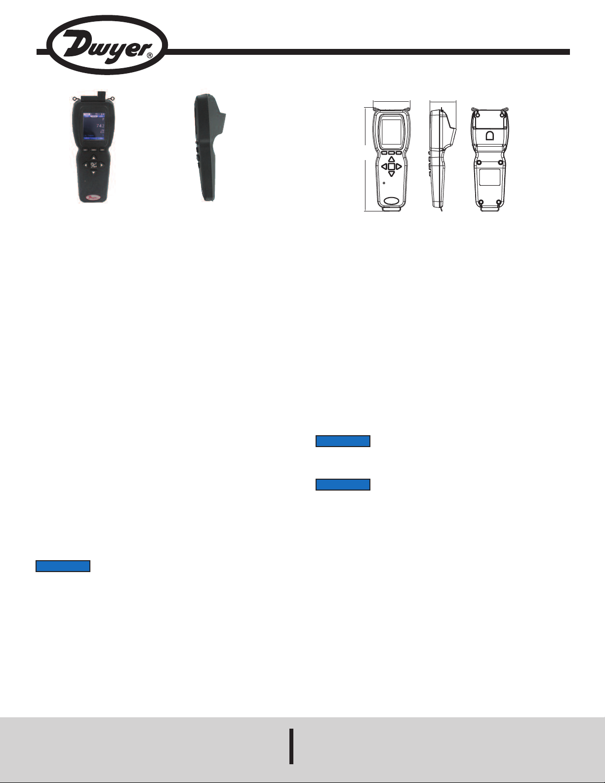
Model UHH - Universal Handheld Test Instrument
3.038
[77.17 mm]
2.169
[55.09 mm]
8.508
[
216.11 mm]
Specifications - Installation and Operating Instructions
ront View Side View
F
Bulletin TE-UHH
he Model UHH Universal Handheld Test Instrument is a highly versatile
T
instrument that offers the utmost flexibility and ease of user operation by having
the capacity to work with a variety of Dwyer Instruments, Inc. compatible sensing
modules and probes. Additional wired and wireless probes or modules are
instantly recognized by the UHH without any user reprogramming or alteration,
llowing seemless sensor addition, upgrade or replacement. See the AQTI Series
a
n the Dwyer Instruments, Inc. catalog or website www.dwyer-inst.com for
i
vailable packages and sensors.
a
The Universal Handheld offers numerous features that enable a technician to
quickly set up and intuitively navigate through their daily activities. Data is stored
via the internal memory or a separate SD card in various auto or manual logging
operations. Logged files can be quickly transferred to a PC or laptop through a
USB cable or by a portable SD card. The display can operate in standard
numerical meter mode, gage mode with an analog needle, gage mode with
additional pass/fail operation zones, and strip chart mode which enables a
simplified visual tracking of the process. The four directional buttons, combined
with the three soft key buttons that are aligned to corresponding screen functions,
allow for quick navigation through the four main operation menus.
The rugged plastic case, with protective thermo-plastic over-mold and the dustshielding rubber caps, permit the unit to handle abuse and properly withstand
dusty environments. The base UHH includes an integral molded compartment that
securely holds wireless modules. The storage compartment offers convenient
transportation of a module with the base instrument during testing. A flexible hand
strap, included with every UHH, allows the base handheld to be safely connected
to a belt, pipe, ladder or similar structure freeing the user's hands to focus on the
sampling test. A 6-pin connector enables one wired probe at a time to be plugged
in to the base instrument without worry of becoming disconnected during sampling.
Additional wireless units can be paired to the base handheld allowing users to
quickly switch between multiple parameters that need to be measured.
The rechargeable battery via the included USB cable provides long term operation
to last through several days of work. At just under 10 oz, the compact UHH base
is lightweight. Included with the UHH is a soft carrying case, universal office / car
charger, and USB cable.
UHH SPECIFICATIONS
anguages: English, German, Italian, Portuguese, Spanish.
L
isplay: OLED, color 240 x 320.
D
Temperature Limits: 5 to 125°F (-15 to 51°C).
Note: When using wireless function: 20 to 125°F (-6 to 51°C).
Battery Charging Limits: 32 to 113°F (0 to 45°C).
esolution: 1 FPM, 0.1 MPS, 0.1 CFM & M
R
Units Air Velocity: FPM, MPH, KN, M/H, M/S K/H, FPS.
Units Flow: CFM, M
Units Temperature: °F, °C.
Handle Enclosure: Thermoplastic elastomer over polycarbonate.
aximum Wireless Distance: 50’ (15 m) typical.
M
ower Requirements: 3 V BR1225 lithium metal battery, installed functional,
P
non-replaceable and 3.7 V lithium ion battery, installed functional, nonreplaceable. (Note: Intended to be operated with power cables less than 3 m in
length).
Memory: 4 MB internal (~50,000 readings).
Weight: 10 oz (283 g).
Supplied With:
AQTI: Soft case; USB cable/charger; Hand strap;
AQTIP: Soft case; Hard case; USB cable/charger; Hand strap, 2GB SD card.
Agency Approvals: CE (not while charging), FCC compliant.
NOTICE
information and files necessary to complete this upgrade in the field or the units can
be returned to the factory to complete any future firmware updates.
NOTICE
used to take measurements.
3
/HR, M3/S, GPM, GPH, GPD, LPS, LPM, LPH.
In some instances, it might be necessary to update the firmware
of the UHH base unit. Dwyer Instruments, Inc. will provide
While UHH is connected to a pc, the unit will act as a storage
device for retrieving log files. During this time, the unit cannot be
3
HR; 0.1°F & °C; RH 0.1%.
/
NOTICE
(1) This device may not cause harmful interference. and (2) this device must accept
any interference received, including interference that may cause undesired
operation.
Cet appareil est conforme à des règlements d'Industrie Canada exempts de licence
standard RSS (s). Son fonctionnement est soumis aux deux conditions suivantes:
(1) Ce dispositif ne doit pas causer d'interférences nuisibles, et (2) cet appareil doit
accepter toute interférence reçue, y compris les interférences pouvant entraîner un
fonctionnement indésirable.
This Class B digital apparatus complies with Canadian ICES-003.
Cet appareil numériqué de la classe B est conformé à la norme NMB-003 du
Canada.
DWYER INSTRUMENTS, INC.
This device complies with Industry Canada license-exempt RSS
standard(s). Operation is subject to the following two conditions:
Phone: 219/879-8000 www.dwyer-inst.com
P.O. BOX 373 • MICHIGAN CITY, INDIANA 46360, U.S.A. Fax: 219/872-9057 e-mail: info@dwyermail.com
Page 2
UHH FEATURE OUTLINE
D MEMORY
S
ARD SLOT
C
ENSOR AND LOGGING
S
ICON LOCATION
CTIVE PROBE
A
NUMBER INDICATOR
AIN MENUS
M
4 DIRECTIONAL ARROWS
ITH POWER/ENTER BUTTON
W
ALLOW QUICK NAVIGATION
LED INDICATES CHARGING
STATUS AND DATA STORAGE
GREEN: INDICATES CHARGING.
NOTE: TURNS OFF WHEN
FULLY CHARGED. YELLOW:
INDICATES A DATA POINT
STORAGE OR THAT UNIT IS IN
SLEEP MODE.
PROTECTIVE RUBBER CAPS
INDUSTRIAL 6-PIN
ROBE CONNECTION
P
3 SOFT KEYS CORRESPOND
TO APPLICABLE ON-SCREEN
HAND STRAP BOTTOM CLIP
AND STRAP
H
OP CLIPS
T
BATTERY
NDICATOR
I
ARGE BACKLIT
L
OLOR OLED
C
UNCTIONS
F
SIDE VIEW
MODULE STORAGE
COMPARTMENT
POWER BUTTON:
• Press to power
ON.
• Hold for 5 seconds
until LED turns RED
and then release to
power OFF.
• Press to store
measurements
during operation.
USB CONNECTION FOR DATA
TRANSFER OR RECHARGING WITH
INTEGRAL PROTECTIVE RUBBER CAP
WIRELESS PROBE
LED INDICATES STATUS:
• Solid Green: Battery
charging
• Blinking Green:
Communicating with UHH
• Blinking Amber (short):
Waiting for communications
with handheld
• Blinking Amber (long):
Probe initializing
• Solid Red: Low battery
USB CONNECTION FOR
RECHARGING WITH INTEGRAL
PROTECTIVE RUBBER CAP
Page 3
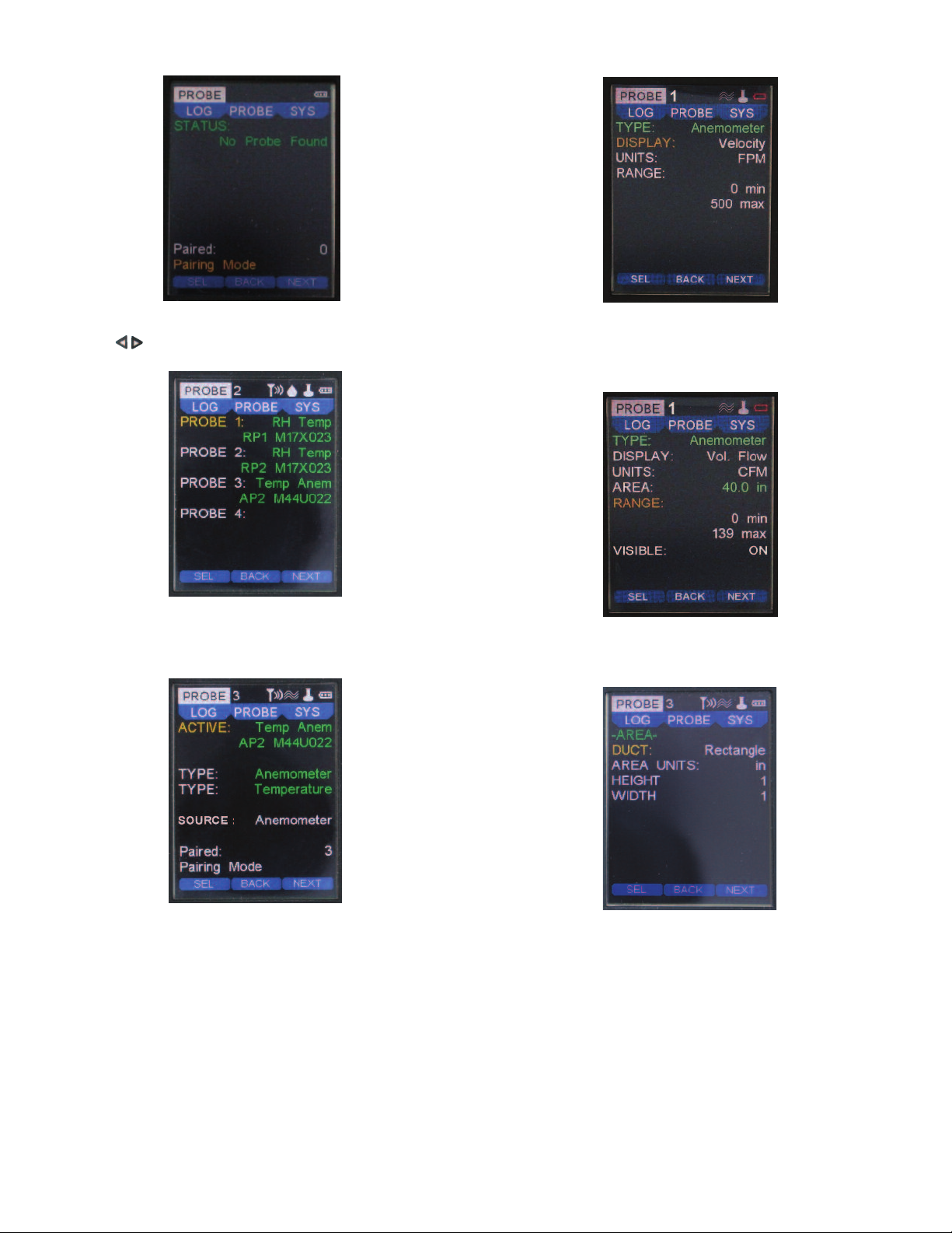
MENU SETUP
Probe Main Menu
Probe Menu
• Press the to scroll through the top main menus.
• When PROBE is highlighted, hit the enter key.
YPE Sub-Menu Anemometer (Velocity Selected)
T
• In this example, the Anemometer can be changed from either Velocity mode or
Vol. Flow mode.
Change the engineering units to be displayed under the UNITS section.
•
ote: Some probes or modules may provide a selectable range which can be
N
djusted here.
a
Pairing Mode Sub-Menu
• After placing the UHH into Pairing Mode, turn on one wireless probe. After a period
of up to 15 to 20 seconds, the UHH screen will update with the information about the
wireless probe that was just turned on.
Note: If probe does not appear, power probe down, then power back on.
Pairing Mode Sub-Menu (cont’d)
• To confirm a proper pairing, select that probe on the list. That probe’s details will
disappear, meaning that probe has been paired. The details of paired probes will
now be visible in the Paired sub-menu. Once paired, no other UHH can pair with
that probe as long as your UHH is communicating with that probe.
• In Paired sub-menu you can see probes that are paired with the UHH. You may
delete probes from being paired by selecting the probe. Once deleted, any UHH can
pair with that probe.
• The currently active probe connected will appear as well as the parameter types
being provided to the UHH. ACTIVE will detail the active probe’s description, model
code and corresponding serial number.
• Select the primary measurement of the home screen under the SOURCE setting.
• To alter the potential modes of the measurements, scroll down to any of the TYPE
sub-menus to select and adjust.
TYPE Anemometer Sub-Menu (Vol. Flow Selected)
• Similarly to when Velocity is selected, applicable engineering units can be chosen
in the UNITS category for Vol. Flow.
• Note an area must be entered.
Area Sub Menu (Vol. Flow Selected)
• If Vol. Flow is chosen, select the AREA category to adjust the DUCT style, the
AREA UNITS, HEIGHT and WIDTH dimensions.
Page 4

In this example, the Temperature range is set and cannot be changed as it is
•
reen and unselectable, however the units may be adjusted and the user can
g
ecide if the temperature will be displayed in the home screen.
d
YPE Sub-Menu Temperature
T
SYS Menu
SETTINGS Sub Menu
Click on the SETTINGS sub menu for language selection as well as the default
•
engineering units. The DATE and TIME can be entered, as well as power
management inactivity time delays for SLEEP and SHUTDOWN.
• The user can program in their name, an identification code or their company name
into the SETTINGS sub menu under OWNER.
SYS Main Menu
• Press the to scroll through the top main menus.
• When SYS is highlighted, push the enter key.
• The STATUS will show how many probes are currently paired.
• The WIRELESS feature may be turned on or off and the display CONTRAST
adjusted here as well.
• If desired, a RESTORE DEFAULT feature is available from this screen.
• Note: FILE displays remaining available memory. If INT is selected in the LOG
main menu the maximum memory is 4 MB. A 2 GB memory card is the maximum
memory the UHH can utilize if SD is selected.
Status Sub Menu
• If you select the STATUS sub menu you can view the firmware edition as well as
the UHH device handle.
VIEW METER Mode
VIEW Menu
• Press the to scroll through the top main menus.
• When VIEW is highlighted, select with the enter key.
• Several viewing modes are available on the home screen from the selections in
this menu.
• The default is METER which displays numerical values.
• The AVERAGE setting calculation is programmed in this menu.
• AVERAGE values may be altered from 1 to 60 seconds.
Page 5

ome Display Under Standard Meter Mode
H
n the home display, multiple parameters may be viewed at the same time
O
epending on the probe or module being used. If two or more parameters are
d
isplayed, the largest reading at the top will always be present and may be
d
switched between parameters (see the PROBE main menu for details). In order to
change the probe selected to be viewed, press the up or down arrow keys.
arameter Hot Key
P
• The three soft keys under the display can be used to quickly access the most
common menu functions.
• The label, above the soft key on the left, describes the active parameter for the
ther two soft keys (i.e. If ANEMO is displayed above the left soft key, the other two
o
oft keys will refer to the velocity or flow parameter that is displayed).
s
Pressing the soft key under the word UNITS cycles through the available
•
engineering units of the selected parameter.
• The center soft key will quickly select the mode of operation (i.e. Velocity or
Volumetric Flow are the available modes of operation for ANEMO).
NOTICE
Volumetric Flow in addition to the engineering units.
•Pressing the left soft key will switch to the next displayed parameter (if one exists)
or will change to the DISPLAY hot keys if there is only one parameter displayed. If
there is multiple parameters displayed, the left soft key will cycle to DISPLAY after
cycling through all of the displayed parameters.
When Volumetric Flow is selected, Settings will show instead of
UNITS as the area and range will also need to be changed for
When DISPLAY is selected, the center soft key will cycle through the display
•
odes of operation which include the current reading, average readings, and peak
m
nd valley readings.
a
Pressing the soft key under CLEAR, will reset the peak and valley readings to the
•
current reading.
• Pressing the left soft key under DISPLAY will switch to the LOG hot keys.
OG Hot Key Home Screen
L
• When LOG is selected, the center soft key will access the Log Menu Settings. In
this menu, the parameter that is going to be logged can be selected, along with the
type of trigger and duration of the Log. See the Log Menu for information about the
Log settings.
If Manual or Event trigger types are selected, then the soft key on the right under
•
TORE will trigger to start a new log. Before starting the log, the user must create
S
he log file and name the log. Once the log is started, the label will change to STOP
t
and pressing the button will stop the current log. For Event triggers, even though
the meter will be in logging mode, there will not be any readings stored until the
current measurement meets the conditions of the event or the minimum set time for
recording a measurement.
NOTICE
LOG appears to have access to the STOP soft key.
• If Single trigger type is selected, then the soft key on the right under STORE will
store the current value into the open log file.
• The log counter will track how many measurements were stored in the current log
file.
• Pressing the left soft key under LOG will switch to the SOURCE hot keys.
When the log is started, the display will return to the home view
and the user will have to push the left soft key several times until
Display Hot Key Home Screen
SOURCE Hot Key Home Screen
• When SOURCE is selected, the center soft key will select the parameter to show
on the larger display at the top.
• The soft key on the right side under HOLD, will freeze the current reading and
change the label above the soft key on the right side to RUN. Pressing the button
again will unfreeze the readings and toggle the label back to HOLD.
• Pressing the left soft key under SOURCE will return to the first parameter’s hot
keys.
Page 6

lternative Home Displays Views
A
n addition to displaying the measurements as a digital meter, the UHH allows the
I
ser to view the measurements either as a gauge, a gauge with range bands, or as
u
graphical strip chart.
a
View GAUGE Mode
In the view menu, choose GAUGE mode to display a digital analog gauge like one
•
imilar to a speedometer. The available range will be adjustable with min and max
s
scale feature.
• Adjust both the min and max for the associated values that will correspond to
the 0° value for min and the 180° value for the max or full scale reading.
OTICE
N
go above this chosen full scale RANGE in the GAUGE setting in the VIEW menu..
Some probes or modules may have selectable ranges that are
programmed in the PROBE menu under RANGE. You cannot
ome View RANGE Mode
H
In this example, the GAUGE has a min of 0 and a max of 500. The RANGE low
•
s 100 while the high is 400.
i
• A green zone on the dial corresponding to the RANGE low/high settings will
appear on the home screen.
Home View GAUGE Mode
• In this example, the min is zero and the max is 500. The live process value is
shown under the gauge dial.
• The mid point will always show at the 90° point on the gauge dial.• Select RANGE
View RANGE Mode
• Select STRIP in the view category in the view menu. This option offers the user
View STRIP Mode
a strip chart style graph with Y axis scaled with the selected major sensor setting
and an X axis showing the selected time.
• The x axis time may be adjusted from 10 to 3,600 seconds.
Home View STRIP Mode
• Besides the time setting shown on the graph, you can program the graph to show
full scale of the range of the sensor, half scale where the top of the Y axis is half
of the full scale, or mid-scale where half the full scale value is displayed in the
middle of the Y axis.
in the VIEW category in the view menu.
• Two sets of min and max will appear listed as GAUGE and RANGE.
• The GAUGE settings are just as in the previous GAUGE view mode and show the
zero and full scale points of the dial.
• The RANGE low and high settings provide a different color green zone to appear
on the dial of the digital gauge. This two color band dial provides a quick
determination during a test if the reading is in the pass or fail zone.
Page 7

LOG Main Menu
LOG Main Menu
• Press the to scroll through the top main menus.
• When LOG is highlighted, push the enter key.
Here you can program the sampling rate of the logging. The sampling RATE may
•
e adjusted from 1 to 3600 seconds between recordings.
b
The FILE FORMAT can be altered from CSV to a TSV downloadable file type.
•
• You can program the TRIGGER to be a manual trigger, a trigger begun by a
programmed event or a single trigger which manually logs a single point by the
push of a button.
Select the LOG to START and STOP the logging function. The LED will flash
•
when the data sample is stored in any logging mode. A log status icon will also
appear at the top to acknowledge a logging session is active. The log counter will
list how many measurements have been recorded in the current log file.
• After the log session has begun, the file name will appear on the FILE row.
You may select under MEDIA to either store data logged files to an SD card if
•
ne is inserted or to INT which is the internal memory.
o
• Select LOG FILES to view all saved files. See view of saved files section for more
details.
You can change the ending of the log to be either a manual end under STOP, or
•
ou can set the STOP to end after a duration.
y
If DURATION is chosen the programmed duration determines how long the log
•
ession will last. It may be set from 1 to 1,440 minutes.
s
OG TRIGGER Event Menu
L
If the TRIGGER has been selected to be Event from the LOG main menu, the
•
creen will appear as shown.
s
• The trigger’s source parameter must be selected to determine the levels for the
event.
• LEVELS provides initiation points where the trigger will begin a log operation.
• The auto trigger EVENT settings can begin INSIDE or OUTSIDE the LEVELS
rigger band.
t
Setting a PRE-TRIG setting to anything other than 0 will provide data recorded to
•
he file for that time period prior to the event trigger initiation.
t
• POST-TRIG sets the duration after the auto trigger event of the log session.
• If the MIN UPDATE is set to anything other than 0, a data point will be captured
at the time of the MIN UPDATE even if the TRIGGER threshold has not been
reached.
• The PRE-TRIG and POST-TRIG can be adjusted over a time period, dependent
on the sample rate, while the MIN UPDATE can be set from 0 to 60 minutes.
LOG TRIGGER Menu
• If the trigger has been selected to be Manual from the LOG main menu, the
screen above will appear.
Home View If Single Trigger Chosen
If Single is chosen, no other parameters are necessary to be programmed. This
mode will allow the right soft key located under STORE in the log hot key home
display to save a single data point into a file. Each subsequent data point will
continue to be stored in that same file until a new file is created in the Log Settings
Trigger Menu shown above when operating a new file, the user can name the file.
Viewing Currently Saved Files
The files that are stored in the internal memory or on the SD card can be viewed
on the display in the Log Main Menu. The MEDIA setting selects the memory
location and the LOG FILES Setting opens the list of currently available log files.
Page 8

ile names can be scrolled through and their data viewed by selecting VIEW.
F
alculated statistics of the data from a file are viewable such as average or peak
C
nd valley by selecting STAT. A file may be deleted by hitting DELETE. To exit this
a
screen and return to the previous, press the left arrow key.
List of Log Files
VIEW of Saved Files
Low Battery Warning
ow Battery Warning
L
he low battery level screen will appear when the UHH detects its charge to be
T
nearing an end. The lithium ion polymer battery is expected to provide
approximately 1000 full charge cycles over its lifespan. Once the battery has
exceeded its useful lifespan, due to varying regulations regarding shipping lithium
atteries, please contact Dwyer Instruments Inc. for details.
b
OTICE
N
ARNING
W
nstruments, Inc. approved charging device in a well ventilated area away from any
I
lammable materials or gases. Do not incinerate. Only charge between 32 to 113°F
f
0 to 45°C).
(
MAINTENANCE/REPAIR
Upon final installation of the Series UHH, no routine maintenance is required. The
Series UHH is not field serviceable. Contact Dwyer Instruments Inc. for return
details (field repair should not be attempted and may void warranty).
t is required before the initial use of the module to fully charge
I
the battery for 12 hours.
Lithium ion polymer batteries are very volatile and can cause a
fire if punctured or severly damaged. Only use a Dwyer
The following will appear after hitting VIEW from the saved files list. Numerical
order value in the saved group along with its file name and format, the DATE, TIME
of that data point and the parameter data values recorded. To scroll through each
data point's information within a file, press the navigation keys. Any data
point may be deleted in their respective file by pressing DEL.
STAT (Statistics) of a Saved File
After selecting STAT from the saved file list screen you will see statistics for all data
within the respective file. Average, Peak and Valley will be visible for all parameters.
The soft key under MORE will display additional parameters if available.
NOTICE
If there are many stored data points on a file, some time may
elapse before the statistics shown above appear.
WARRANTY/RETURN
Refer to “Terms and Conditions of Sales” in our catalog and on our website. Contact
customer service to receive a Return Goods Authorization number before shipping
the product back for repair. Be sure to include a brief description of the problem
plus any additional application notes.
ACCESSORIES
Model
AP1
RP1
VP1
AP2
RP2
VP2
UHH-STRAP
UHH-ICHRG
UHH-CBL
UHH-SD
UHH-C1
UHH-C2
Description
Thermo-anemometer air velocity & temperature probe with coiled
cable
Thermo-hygrometer & temperature probe with coiled cable
100 mm vane thermo-anemometer air velocity, temperature,
humidity probe
Wireless thermo-anemometer air velocity & temperature probe
Wireless thermo-hygrometer humidity & temperature probe
Wireless 100 mm vane thermo-anemometer air velocity,
temperature, humidity probe
UHH hand strap
UHH charger with international adapters
USB cable
2GB SD card
Soft carrying case
Heavy duty hard case with pre-cut foam inserts for additional
sensor storage
©Copyright 2014 Dwyer Instruments, Inc. Printed in U.S.A. 5/14 FR# 02-443875-00 Rev. 6
DWYER INSTRUMENTS, INC.
Phone: 219/879-8000 www.dwyer-inst.com
P.O. BOX 373 • MICHIGAN CITY, INDIANA 46360, U.S.A. Fax: 219/872-9057 e-mail: info@dwyermail.com
 Loading...