

Page 1
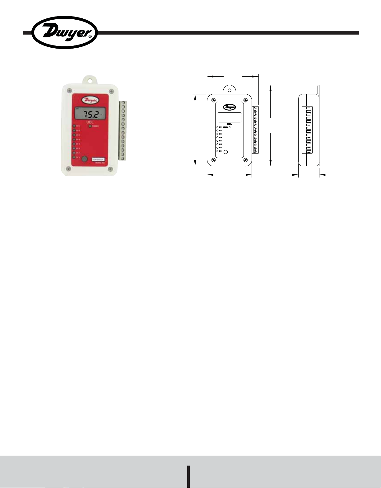
Series UDL Universal Input Data Logger
Specifications - Installation and Operating Instructions
3-1/16
[77.79]
4-13/16
4-1/4
[107.95]
[122.24]
Bulletin DA-UDL
The Series UDL Universal Input Data Loggers are available with 0, 2, or
4 universal inputs. Each universal input can be individually configured to
accept a thermocouple, RTD, thermistor , voltage, or current input. All Series
UDL data loggers have an internal temperature sensor and a digital input
which can be used as a trigger to start logging or as a pulse counter for interfacing with flow meters or other sensors with a pulse output. Optional features include an internal humidity sensor, an LCD display, and an external
humidity and temperature sensor. The Series UDL loggers interface to the
USB port of a PC. The unit includes software, USB connection cable and
installed battery .
SOFTWARE FEA TURES
• Graphing of downloaded data
• Zooming function
• T emperatur e in °F or °C
• Up to two traces per graph
• Multiple traces per graph (Full Version Only)*
• Exporting to spreadsheet (Full Version Only)*
• Viewing the data table (Full Version Only)*
• Calculating Mean Kinetic T emperatur e (MKT) (Full Version Only)*
• Emailing graphs (Full Version Only)*
*In order to obtain the Full Version Only features, the software upgrade key
must be purchased. To access the full version, the software key is inserted
into a USB port on the PC and the full version features are automatically
added onto the existing software.
2-5/8
[66.68]
1-1/4
[31.75]
SPECIFICATIONS
Inputs: RTD, Thermocouple, Thermistor, Current, Voltage, Slidewire.
Range: Internal temperature: -22 to 158°F (-30 to 70°C); Internal RH: 0
to 100%; External temperature: -22 to 158°F (-30 to 70°C); External RH:
0 to 100%.
Accuracy: Internal temperature: ±1°F (± 0.5°C); External temperature:
±1°F (±0.5°C) over 30 to 122°F (0 to 50°C), ±2°F (±1°C) over -30 to
32°F (-30 to 0°C) and 122 to 158°F (50 to 70°C); Internal/External RH:
±2.0%RH over 10%-90%, ±4.0%RH over 0-10% and 90-100%RH.
Memory Size: 0 or 2 universal inputs: 62,000 readings; 4 universal
inputs: 128,000 readings.
Resolution: All universal inputs: 16 Bit; Internal & external temperature:
12 Bit; Internal & external RH: 8 Bit.
Sampling Method: Stop when full or continuous logging (wrap when
full).
Sampling Rate: Selectable from 1 second to 24 hours.
Computer Requirements: Windows® 98, Windows® 2000, Windows
®
ME, Windows NT®, Windows® XP, and Windows V ista®operating system
with 16 MB RAM, one free USB port.
Power Requirements: 3.6VDC lithium AA.
Battery Life: 6 years (approx.).
Alarms: Programmable high/low.
Interface: USB port (cable included).
Housing Material: ABS plastic.
Weight: 5.8 oz (165 g).
Agency Approval: CE, RoHS.
Windows®, Windows NT®, and Windows Vista®are registered trademarks of Microsoft
Corporation.
DWYER INSTRUMENTS, INC.
Phone: 219/879-8000 www.dwyer-inst.com
P.O. BOX 373 • MICHIGAN CITY, INDIANA 46361, U.S.A. Fax: 219/872-9057 e-mail: info@dwyer-inst.com
Page 2
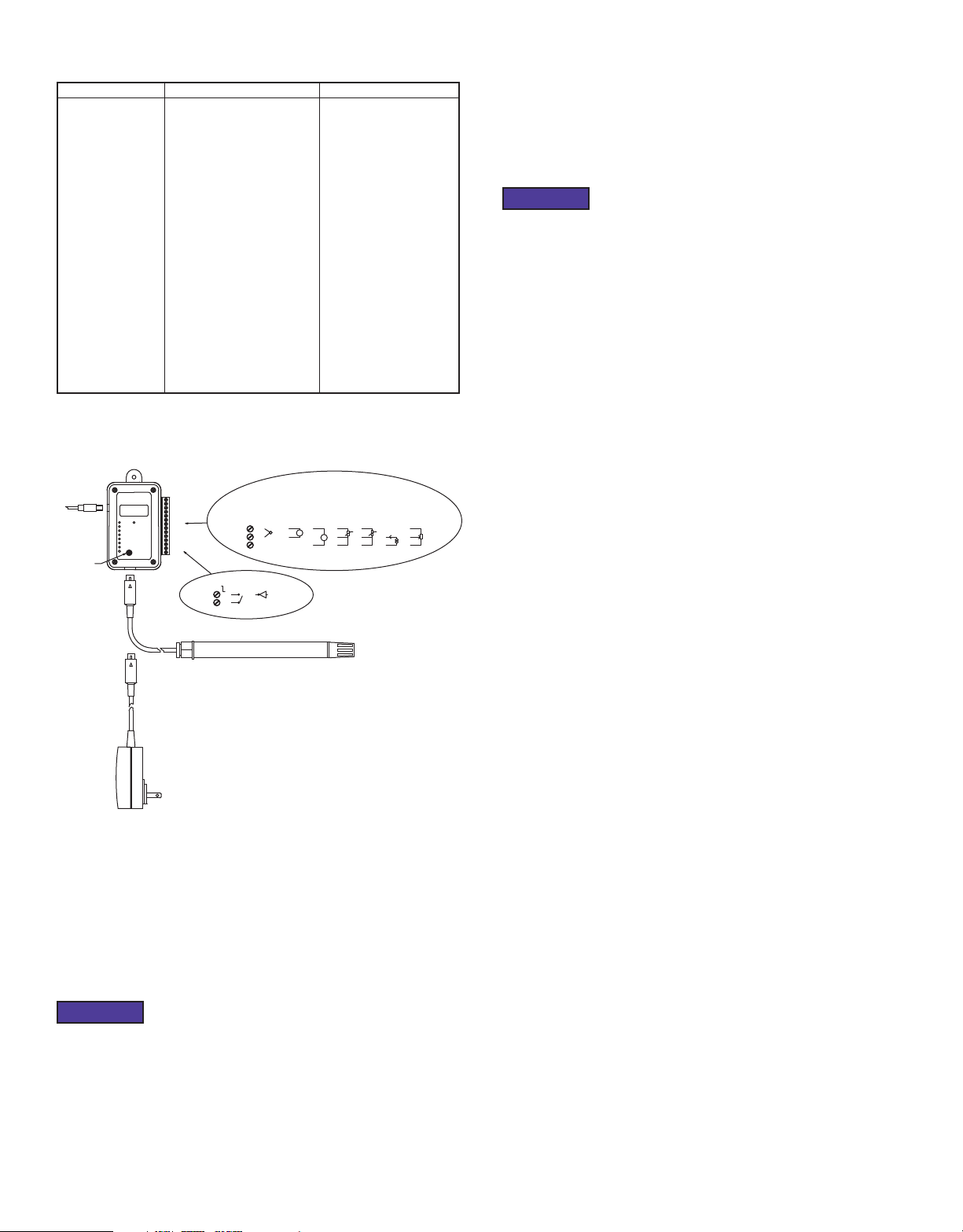
INPUT TYPES AND CONNECTIONS
B
+
+
+
mV
V
PTC
NTC
Inputs
Pt100 EN60751
Pt100 JISC
Ni100
Ni120
Cu10
Cu100
Thermocouple J
Thermocouple K
Thermocouple T
Thermocouple R
Thermocouple S
Thermocouple B
Thermocouple N
Thermistor TH-001
Thermistor TH-002
Thermistor TH-003
Current (4 to 20 mA)
Voltage (±100 mVDC)
Voltage (0 to 1 VDC)
Voltage (0 to 10 VDC)
Slidewire
Range
-328 to 1292°F (-200 to 700°C)
-148 to 854°F (-100 to 457°C)
-76 to 356°F (-60 to 180°C)
-112 to 446°F (-80 to 230°C)
-328 to 500°F (-200 to 260°C)
-148 to 500°F (-100 to 260°C)
-328 to 2192°F (-200 to 1200°C)
-328 to 2498°F (-200 to 1370°C)
-328 to 752°F (-200 to 400°C)
212 to 3200°F (100 to 1760°C)
212 to 3200°F (100 to 1760°C)
1292 to 3308°F (700 to 1820°C)
-292 to 2372°F (-180 to 1300°C)
-40 to 257°F (-40 to 125°C)
-22 to 194°F (-30 to 90°C)
-22 to 221°F (-30 to 105 °C)
0.1 to 21 mA
-110 mV to 110 mV
0 VDC to 1.1 VDC
0 VDC to 11 VDC
100 ohms to 10 kilo-ohms
The sensors are connected as shown below.
Accuracy
± 0.5°F (± 0.1°C) ± 0.1% rdg
± 0.5°F (± 0.1°C) ± 0.1% rdg
± 0.5°F (± 0.2°C) ± 0.1% rdg
± 0.5°F (± 0.2°C) ± 0.1% rdg
± 6°F (± 3°C) ± 0.5% rdg
± 0.5°F (± 0.2°C) ± 0.1% rdg
± 1°F (± 0.5°C) ± 0.1% FSD
± 1°F (± 0.5°C) ± 0.1% FSD
± 1°F (± 0.5°C) ± 0.1% FSD
± 1°F (± 0.5°C) ± 0.2% FSD
± 1°F (± 0.5°C) ± 0.2% FSD
± 1°F (± 0.5°C) ± 0.2% FSD
± 1°F (± 0.5°C) ± 0.1% FSD
± 1°F (± 0.5°C)
± 1.5°F (± 0.6°C)
± 1°F (± 0.5°C)
± 0.01% FSD
± 0.01% FSD
± 0.01% FSD
± 0.01% FSD
± 0.02% FSD
T o issue the logger, from the Logger Operations menu select UDL Network.
In the Explorer window that comes up, RIGHT CLICK on the device icon and
select Configure.
Enter relevant parameters within the General, Input Setup, Manifest T ext, and
Input T rim buttons on the left. Click the Issue button when complete.
NOTICE
Issuing the parameters erases all data currently stored in the logger.
INITIAL SETTING
The first time a logger is set, you will be prompted to enter an Owners Manifest
and a Passcode. This is the only time you will be asked for this information
and it cannot subsequently be changed.
Owners Manifest is a label for the logger normally used to record details of
the owner and/or details related to the logger such as date purchased, shipment, application, etc. (256 characters).
If the default Passcode is changed, and if it is lost, not even the factory can
retrieve it. If this happens then the logger cannot be issued ever again. It is
recommended that the Passcode NOT be changed.
USB
Cable
Humidity
Sensor
UDL-xxx Series
1.8.8.8
CH1A
CH1B
CH1C
CH2A
CH2B
CH2C
CH3A
CH3B
CH3C
CH4A
CH4B
CH4C
DIG+
DIG-
DIG+
DIG-
A
B
C
-ve Edge Trigger
0 to 1V,
±100mV
Thermocouple
mV
RTD
0 to 10V
PTC
Thermistor
NTC
External Temperature and Humidity Sensor
External Power Supply (Optional)
Having selected the correct sensor type, the appropriate connections can
be made. The type of sensor used must be selected via the software prior
to issue.
The inputs are isolated from the communications port but not from each
other . Care should be taken to avoid gr ound loop pr oblems.
CONFIGURATION
Once a password has been entered, the Configuration window will come up.
NOTICE
Whenever a new type of data logger is connected to the PC, the correct data
logger will have to be selected from the Configuration window. From the
Options menu, select Configuration to bring up the Configuration window.
mA
Slidewire
DOWNLOAD DATA
Download data by connecting the logger to the PC.
From the Logger Operations menu select UDL Network.
In the Explorer window that comes up, RIGHT CLICK on the device icon and
select Download. Data is then presented graphically . At this stage, data can
be saved to the computer .
GENERAL BUTTON
Location allows a 12 character description to be entered.
Data T ypedefines the value that is stored to memory .
Point is when every sampled measurement is stored directly to memory.
Averaging is the average value per period stored.
Maximum is the maximum value per period stored.
Minimum is the minimum value per period stored.
Read Rate is the rate at which the sampling points are measured, or the
period.
Log Interval is the time between when the sample points are stored.
Display Update is how often the LCD updates. This also defines the flash
rate of the LEDs, so setting it to a longer interval will improve battery life.
Stop when Full means that when the logger’ s memory is full it will stop logging.
Wrap when Full means that when the logger’s memory is full, it will overwrite the oldest data and continue to log.
In the Graph tab, choose the desired temperature units and other graph
options.
In the Device tab, select the correct logger by clicking the button displaying
the device icon matching the logger you are using.
Log Size sets the effective memory size in readings per channel. The Default
option sets the memory size to the maximum available, while the Custom
option means that a smaller maximum memory can be set.
Page 3

INPUT SETUP BUTTON
J10PIN1
J10PIN2
J10PIN4
Enabled channels are chosen from the tick boxes to the left of the channel
numbers.
ALARM SETUP
Within the Input Setup button, the Alarm Setup section allows a high and low
value to be entered per channel.
Visual On shows which channels will be displayed on the LCD.
Descriptor allows a 12 character description of the input to be entered.
Inputs for temperature and humidity are fixed. Universal inputs can be cho-
sen.
Linearisation is different depending on the type of universal sensor chosen.
The Input Scaling section allows the inputs to be scaled in engineering units.
If the Icon column is chosen to be NONE, then a unit can be entered in the
Unit column. The chosen icon or the entered unit will appear on printouts,
etc.
Channel 9 stores the number of counts per log interval for the frequency
inputs, so channel 9 cannot be displayed on the LCD or on the LED indicators.
MANIFEST TEXT BUTTON
Owner Name is the Owners Manifest and is only set the first time the log-
ger is issued.
User Manifest T extis a label for the logger that takes up to 256 characters
and can be changed every time the logger is issued.
INPUT TRIM BUTTON
This allows span and offset corrections to be made. However , changing these
will change the calibration which may result in inaccurate readings.
The Timecolumn specifies how many times the high/low value can be crossed
before an alarm is tripped.
The LED on the logger changes from flashing green to red when an alarm is
tripped on that channel.
The alarms are armed the first time the input is in a non-alarm range. However ,
if Delayed or T rigger Start is enabled, then the alarms are armed as soon as
it starts logging.
FREQUENCY INPUT
All loggers can measure frequency through the use of a digital input facility.
The digital input can be either a Potential free contact, TTL, C MOS, or Open
Collector transistor . It can measure fr equencies of up to 32 KHz.
If the unit is measuring frequencies less than 50 Hz, then to prevent contact
bounce that could give false readings, the internal filter should be activated.
To activate, unscrew the 4 screws from the front of the unit and reposition
the internal jumper ring so that the jumper will be in position B. The jumper
is visible close to the edge connector .
It is not recommended that the internal filter should be activated for frequencies greater than 50 Hz and should thus be left in its initial position A.
JUMPER1
J11
32KHz
A
B
50Hz
Changing these values is not often done. The limits for the span are 0.95 to
1.05 and the limits for the offset are ±5.
T o change these, the password enter ed the first time the program was opened
is required.
STAR T LOGGING
There are multiple ways that the data logger can begin to log data.
Within the General button:
Delayed Start means the user can select a specific date and time when it
starts logging.
Magnetic Start means the logger starts when the magnet is swiped across
the appropriate place on the back of the logger. The orange LED will blink
until the logger has been swiped.
Digital Start means the logger starts when an external digital signal triggers
it.
Within the Input Setup button:
Trigger Setup allows a low and/or high value to be entered in engineering
units. The logger only logs when the input value goes below the low value or
exceeds the high value.
If none of these options are chosen, the logger will start as soon as the Issue
button is pressed.
J1
CH1A
J10PIN4
J10PIN2
J10PIN1
PIN 1
SIG-1111-01
CH1B
CH1C
CH2A
CH2B
TH1
CH2C
CH3A
CH3B
CH3C
CH4A
CH4B
CH4C
FREQ GND
FREQPLS
J11
32KHz
A
B
50Hz
REAL TIME DISPLAY
To display each channel’s input value in real time electrical units, from the
Logger Operations menu select UDL Network.
In the Explorer window that comes up, RIGHT CLICK the device icon and
select Realtime.
The displayed value is initially scanned within one second of the issue, and
then updates according to the Read Rate value.
Page 4

MAINTENANCE
Upon final installation of the Series UDL Data Logger , no routine maintenance
is required.
Fast logging will considerably shorten the battery life. T o preserve battery life,
it is recommended to use the longest practical sampling rate, and when the
logger is not in use to set the sampling rate to the longest option.
A periodic check of the system calibration is recommended. The Series UDL
is not field serviceable and should be returned if repair is needed (field repair
should not be attempted and may void warranty). Be sure to include a brief
description of the problem plus any relevant application notes. Contact customer service to receive a return goods authorization number before shipping.
©Copyright 2009 Dwyer Instruments, Inc. Printed in U.S.A. 4/09 FR# R6-443607-00 Rev. 1
DWYER INSTRUMENTS, INC.
Phone: 219/879-8000 www.dwyer-inst.com
P.O. BOX 373 • MICHIGAN CITY, INDIANA 46361, U.S.A. Fax: 219/872-9057 e-mail: info@dwyer-inst.com
 Loading...