

Page 1
Bulletin TE-TTW
5 [127]
®
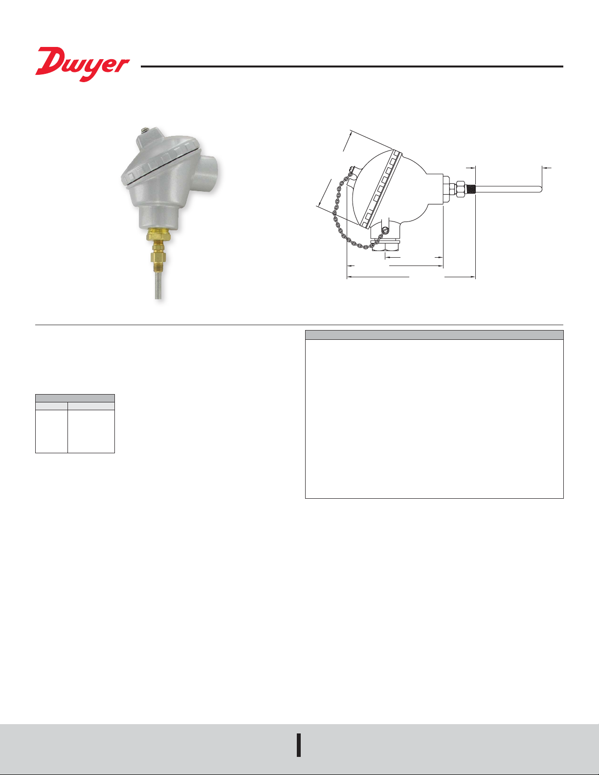
Series TTW Weatherproof Immersion Temperature Transmitter
Specications - Installation and Operating Instructions
The Series TTW Weatherproof Immersion Temperature Transmitter combines
three popular products into a single package. Our TBU series head mounted
temperature transmitter is factory mounted into our A-709 enclosure. A Pt100RTD
version of our TE series is wired to the transmitter, giving insertion lengths up to 18”.
Each transmitter is factory programmed and calibrated to output a 4 to 20 mA signal
proportional to the 32 to 212°F (0 to 100°C) temperature range.
MODEL CHART
Model Probe Length
TTW-104
TTW-106
TTW-108
TTW-112
TTW-118
4˝
6˝
8˝
12˝
18˝
Ø3-15/64
[Ø82.15]
2-15/64
3-3/4
[95.25]
SPECIFICATIONS
TEMPERATURE SENSOR
Accuracy: ±3°F (±1.7°C).
Temperature Limits: Operating: -40 to 302°F (-40 to 150°C).
Sensor Curves: Pt100 RTD (TE Series Curve D).
TEMPERATURE TRANSMITTER
Input Range: -328 to 986°F (-200 to 530°C).
Output: Two-wire 4 to 20 mA.
Output Impedance: 600 Ω @ 24 VDC.
Power Requirements: 12 to 35 VDC.
Accuracy: ±0.2% FS.
Temperature Limits: -40 to 185°F (-40 to 85°C).
Response Time: <100 ms.
[56.75]
[PROBE LENGTH]
+3/8 [9.52]
OPERATION
The sensor offset can be adjusted through the software. The USB cable may be
connected to the transmitter without causing any measurement errors.
The user must select the sensor and most suitable range to the process. The chosen
range must not exceed the maximum range specied for that sensor and should not
be narrower than the minimum range for that same sensor.
It is important to note that the transmitter accuracy is based on the maximum range of
the sensor used, even when a narrower range is programmed.
Note: When Pt100 simulators are used with the transmitter, make sure the excitation
current is compatible with the Pt100 excitation current of the transmitter, which is 0.8
mA.
DWYER INSTRUMENTS, INC.
P.O. BOX 373 • MICHIGAN CITY, INDIANA 46360, U.S.A.
ENCLOSURE
Temperature Limits: -40 to 212°F (-40 to 100°C).
Rating: NEMA 4X (IP65).
Material: Painted aluminum housing.
Phone: 219/879-8000
Fax: 219/872-9057
www.dwyer-inst.com
e-mail: info@dwyermail.com
Page 2

CONFIGURATION
TO PC USB PORT
PT100 SENSOR
LOAD
+
The factory conguration for the transmitter is sensor Pt100 with a 2-wire set up
and a range of 0 to 100°C with upscale error condition. If this conguration ts the
system requirement, no further action is required and the transmitter is ready to be
installed. Changes to the conguration are possible through the software. The 2-wire
conguration of the Pt200 sensor is shown below in Figure 1.
INSTALLATION KEYNOTES
Section of the cable used: 0.14 to 1.5 mm
Recommended torque in the terminal: 0.8 Nm.
Sensor signals conductors must go through the plant system
NOTICE
separate from power leads (loop), if possible in grounded conduits.
2
.
NOTICE
CONFIGURATION
During the setup, the transmitter is powered by the USB, not requiring an external
power supply.
The USB connection port (interface) is not electrically isolated
from the transmitter’s input.
2-WIRE
JUMPER
6
3
2
1
-
-
+
Figure 1
NOTICE
NOTICE
NOTICE
SAFETY INFORMATION
Any control system design should take into account that any part of the system has the
potential to fail. This product is not a protection or safety device and its alarms are not
intended to protect against product failures. Independent safety devices should always
be provided if personnel or property are at risk.
Product performance and specications may be affected by its environment and
installation. Its user’s responsibility to assure proper grounding, shielding, cable routing
and electrical noise ltering, in accordance with local regulations, EMC standards and
good installation practices.
MAINTENANCE/REPAIR
Upon nal installation of the Series TTW, no routine maintenance is required. The
Series TTW is not eld serviceable and is not possible to repair the unit. Field repair
should not be attempted and may void warranty.
WARRANTY/RETURN
Refer to “Terms and Conditions of Sale” in our catalog and on our website. Contact
customer service to receive a Return Goods Authorization number before shipping the
product back for repair. Be sure to include a brief description of the problem plus any
additional application notes.
The instruments must be powered from the instrumentation power
supply circuit.
In control and monitoring applications, it is essential to consider
what can happen when any part of the system fails.
It is recommended to use suppressors in contact coils, solenoids
and any inductive load.
The transmitter setup can also be made by connecting it to the loop using the loop
power supply. There is no electrical insulation between the transmitter and the
communication port (interface), therefore it is not recommended to congure it with
the sensor inlet connected to the process. See Figure 2 for the USB cable connections
when it is loop powered.
6
3
2
1
POWERED CURRENTS LOOP
USB CABLEPLUG MICRO B
Figure 2
TRANSMITTER
PLUG A
DWYER INSTRUMENTS, INC.
P.O. BOX 373 • MICHIGAN CITY, INDIANA 46360, U.S.A.
Printed in U.S.A. 8/18 FR# 444484-00©Copyright 2018 Dwyer Instruments, Inc.
Phone: 219/879-8000
Fax: 219/872-9057
www.dwyer-inst.com
e-mail: info@dwyermail.com
 Loading...