

Page 1
Bulletin E-90-TTE
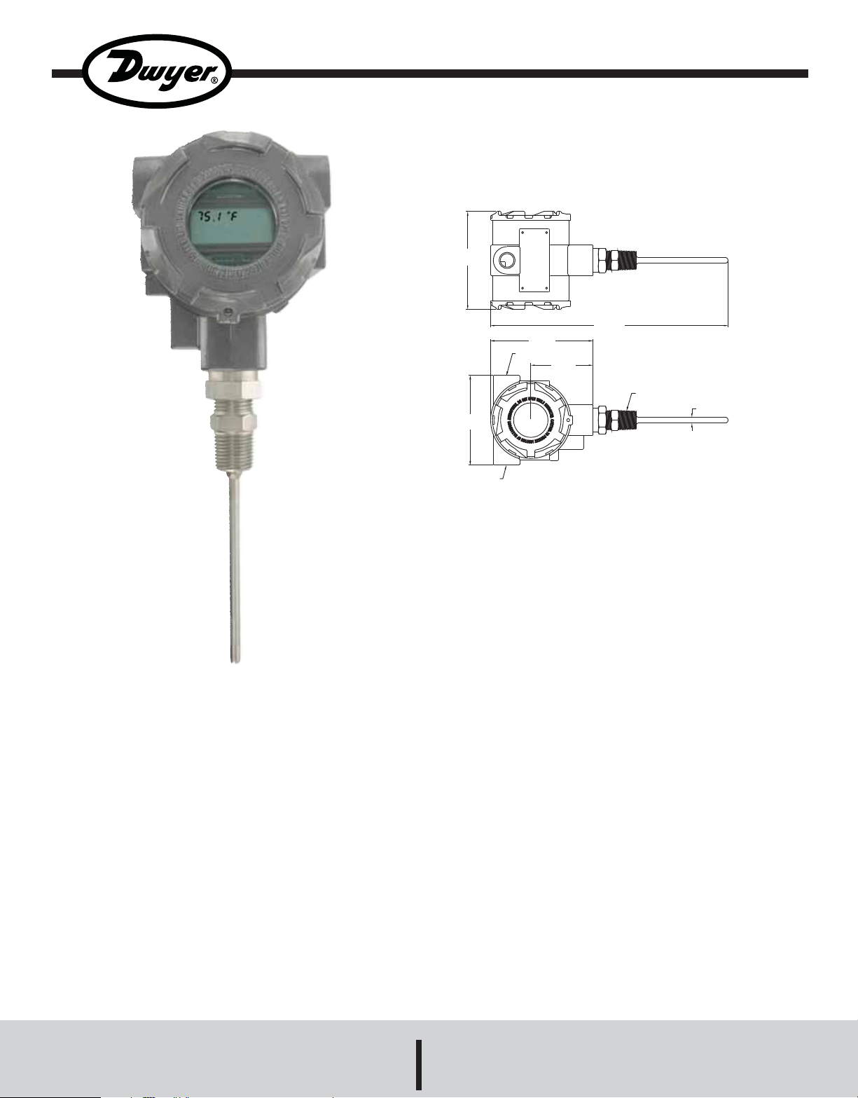
Series TTE Explosion-Proof RTD Temperature Transmitter
Installation and Operation Instructions
4-9/32
[108.74]
10-23/64
[263.13]
[113.51]
1/2 NPT
4-15/32
2-23/32
[69.06]
The Series TTE Explosion-Proof RTD Temperature
Transmitter is the ideal product for hazardous
temperature measurement applications. The TTE series has
seven pre-programmed temperature ranges that are
selectable via an internal dip switch. For those applications
that need a custom range, the transmitter can be easily
configured for any range between -30 to 250°F with a
minimum span of 40°F. The span and zero can be quickly
adjusted with a simple push button design. The compact
housing allows for the transmitter to be mounted in virtually
any application.
The Series TTE is ideally suited for refrigeration, building
automation, commercial hot water heaters and boilers, and
water chillers applications.
3-29/32
[99.22]
1/2 NPT
1/2 NPT
ø1/4
[ø6.35]
SPECIFICATIONS
Temperature Sensor: Pt1000, 0.00385 DIN.
Output Temperature Ranges: User selectable – any range
between –30 to 250°F with a minimum span of 40°F.
Temperature Limits: Ambient: 0 – 158°F (-18 to 70°C).
Process: -30 to 250°F (-34.4 to 121.1°C).
Accuracy: Transmitter +/0.1% F.S. Probe +/-0.3% F.S.
Thermal Drift Effects: +/-0.02%/°C max.
Response Time: 250 ms.
Wetted Materials: 316 stainless steel.
Process Connection: 1/2˝ male NPT.
Conduit Connection: 1/2˝ female NPT.
Probe Length: 2˝ to 18˝ (depending on model).
Pressure Limits: 2000 PSI.
Power Requirements: 10 to 35 VDC.
Output Signal: 4-20 mA (two wire loop powered).
Optional Display: 2 lines X 8 character LCD.
Enclosure Rating: NEMA 4X (IP66) and explosion-proof
for Class I, Groups B, C, D; Class II, Groups E, F, G; Class
III.
Weight: 2 lb 8 oz (1134 g).
Agency Approvals:FM, CE.
DWYER INSTRUMENTS, INC.
Phone: 219/879-8000 www.dwyer-inst.com
P.O. BOX 373 • MICHIGAN CITY, INDIANA 46361, U.S.A. Fax: 219/872-9057 e-mail: info@dwyer-inst.com
Page 2
INSTALLATION
1. Location: Select a location where the temperature of the
transmitter will be between 0 and 158°F. Distance from
the receiver is limited only by total loop resistance.
2. Position: The transmitter is not position sensitive. Units
with the optional display should be mounted for ease of
viewing the display.
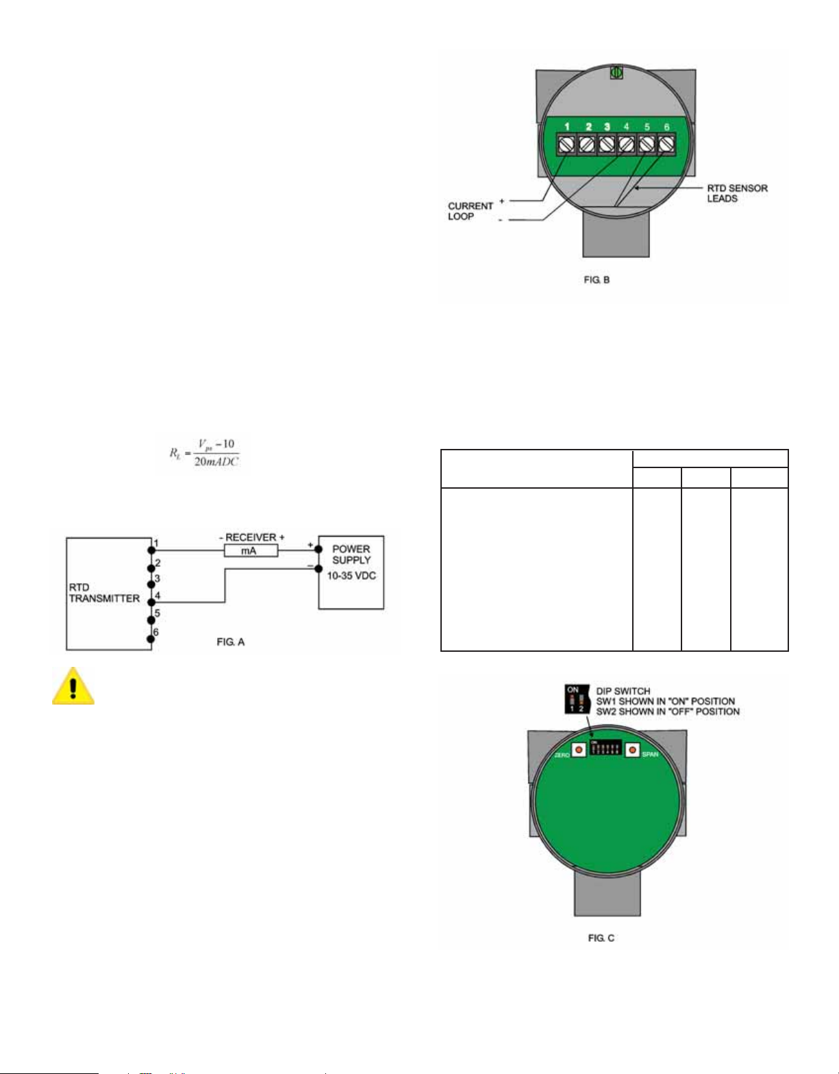
3. Electrical Connection:
Wire Length - The maximum length of wire connecting
the transmitter and receiver is a function of wire size and
receiver resistance. Wiring should not contribute more
than 10% of the receiver resistance to total loop
resistance. For extremely long runs (over 1000 feet),
choose receivers with lower resistance to minimize the
size and cost of connecting leads.
Current (4-20 mA) Output Operation
An external power supply is required. See Fig. A for diagram
of the connection of the power supply, transmitter and
receiver. The range of appropriate receiver load resistance
(RL) for the DC power supply voltage available is expressed
by the formula:
Shielded cable is recommended for control loop wiring.
Explosion-Proof Installation Notes:
1. Install in accordance with any applicable national electric
code.
2. Plug unused conduit openings. Plug must engage a
minimum of 5 threads.
3. Use a conduit seal within 18 inches of conduit entry.
4. Disconnect power before servicing.
Temperature Range Selection
The RTD Transmitter has 7 built in temperature ranges and
a user settable range that are selectable by setting the Dip
Switch located inside the housing (Fig C). Switches 2, 3,
and 4 are used to set the range. To set the desired range,
unscrew and remove the cover and set the Dip Switch
according to the following table:
DIP SWITCH
Selectable Ranges 2 3 4
40 to 90°F (4.4 to 32.2°C) OFF OFF OFF
-20 to 140°F (-28.9 to 60°C) ON OFF OFF
0 to 100°F (-17.8 to 37.8°C) OFF ON OFF
30 to 240°F (-1.1 to 115.6°C) ON ON OFF
32 to 212°F (0 to 100°C) OFF OFF ON
32 to 122°F (0 to 50°C) ON OFF ON
-30 to 65°C (-1.1 to 18.3°C) OFF ON ON
User Settable ON ON ON
Electrical connections to the RTD Transmitter are made to
the terminal block located inside the housing. Unscrew and
remove the cover. W ire as shown in FIG. B.
Page 3

Setting and Calibrating the User Settable Range
By setting SWITCH 2, 3, and 4 on, the RTD T ransmitter may
be adjusted to a custom user specified range. The range
may be any values between –30°F and +250°F (-34 to
+121°C) with a MINIMUM SPAN of 40°F (22°C).
Equipment Required
In order to calibrate the unit for a custom range, a precision
RTD simulator that can simulate a 1000 OHM DIN type RTD
or precision decade box is required. The device must be
capable of generating the correct RTD resistance to 0.1% or
better.
Calibration Procedure
1. Set DIP SWITCHES 2, 3 and 4 ON.
2. Remove the RTD sensor leads from terminals 5 and 6
(Fig. B). Connect the precision RTD simulator or
decade box to terminals 5 and 6.
3. Wire instrument as previously discussed. A current
meter may be wired in series with the unit to verify the
correct current output, but this is not necessary for
calibration. Apply power to the unit.
4. If a precision RTD simulator is used, make sure it is set
to simulate a 1000 OHM DIN 0.00385 RTD. Then set it
to the desired minimum temperature. If a decade box is
used refer to the table in Appendix A (°F) or Appendix B
(°C) and set it to the resistance that represents the
desired minimum temperature.
5. Press the ZERO button. If the unit has the optional LCD,
the display will read ZERO OK momentarily. If a current
meter is wired, it will read 4.00mA.
6. Repeat step 4 using the value for the maximum desired
temperature.
7. Press the SPAN button. If the unit has the optional LCD,
the display will read SPAN OK momentarily. If a current
meter is wired, it will read 20.00mA.
8. Tur n off power to the unit. Disconnect the RTD simulator
or decade box and reconnect the RTD sensor to
terminals 5 and 6. Calibration is complete.
°F and °C Selection
If the unit has the optional LCD display, DIP SWITCH 1 sets
the display to read in °F or °C. SWITCH 1 “OFF” = °F
SWITCH 1 “ON” = °C.
Output Current Display
If the unit has the optional LCD display, the lower display will
show the output current if DIP SWITCH 5 is “ON”. Setting
DIP SWITCH 5 “OFF” causes the lower display to be blank.
Open RTD Protection
Upon detecting an open RTD, the unit may be set to force
the output to read 3.5mA or 21mA based upon the setting
of DIP SWITCH 6.
SWITCH 6 “OFF”, output forced to 3.5mA
SWITCH 6 “ON”, output forced to 21mA
Calibration
The unit requires no calibration. An internal precision resistor
continually self calibrates the unit. Calibration may be
verified by removing the sensor leads and testing the unit
against a precision RTD simulator or a precision decade
box. If the unit is found to out of calibration it must be
returned to the factory for service.
MAINTENANCE
Upon final installation of the Series TTE Explosion Proof RTD
Temperature Transmitter, no routine maintenance is
required. A periodic check of the system calibration is
recommended. The Series TTE is not field serviceable and
should be returned if repair is needed (field repair should not
be attempted and may void warranty). Be sure to include a
brief description of the problem plus any relevant application
notes. Contact customer service to receive a return goods
authorization number for shipping.
Note: The calibration procedure does not effect the
calibration of any of the built in ranges.
Page 4

Appendix A - RTD Table, ˚F PIt 1000 DIN 0.00385
Values are in ohms
TEMP, °F -0 -1 -2 -3 -4 -5 -6 -7 -8 -9
-30 864.7
-20 886.6 884.4 882.2 880.0 877.8 875.6 873.5 871.3 869.1 866.9
-10 908.5 906.3 904.1 901.9 899.7 897.6 895.4 893.2 891.0 888.8
-0 930.3 928.2 926.0 923.8 921.6 919.4 917.2 915.0 912.9 910.7
TEMP, °F 0 1 2 3 4 5 6 7 8 9
0 930.3 932.5 934.7 936.9 939.1 941.2 943.4 945.6 947.8 950.0
10 952.1 954.3 956.5 958.7 960.9 963.0 965.2 967.4 969.6 971.7
20 973.9 976.1 978.3 980.4 982.6 984.8 987.0 989.1 991.3 993.5
30 995.7 997.8 1000.0 1002.2 1004.3 1006.5 1008.7 1010.9 1013.0 1015.2
40 1017.4 1019.5 1021.7 1023.9 1026.0 1028.2 1030.4 1032.5 1034.7 1036.9
50 1039.0 1041.2 1043.4 1045.5 1047.7 1049.9 1052.0 1054.2 1056.3 1058.5
60 1060.7 1062.8 1065.0 1067.1 1069.3 1071.5 1073.6 1075.8 1077.9 1080.1
70 1082.3 1984.4 1086.6 1088.7 1090.9 1093.0 1095.2 1097.4 1099.5 1101.6
80 1103.8 1106.0 1108.1 1110.3 1112.4 1114.6 1116.7 1118.9 1121.0 1123.2
90 1125.3 1127.5 1129.6 1131.8 1133.9 1136.1 1138.2 1040.4 1142.5 1144.7
TEMP, °F 0 1 2 3 4 5 6 7 8 9
100 1146.8 1149.0 1151.1 1153.3 1155.4 1157.6 1159.7 1161.8 1164.0 1166.1
110 1168.3 1170.4 1172.6 1174.7 1176.9 1179.0 1181.1 1183.3 1185.4 1187.6
120 1189.7 1191.8 1194.0 1196.1 1198.3 1200.4 1202.5 1204.7 1207.0 1208.9
130 1211.1 1213.2 1215.4 1217.5 1219.6 1221.8 1223.9 1226.0 1228.2 1230.3
140 1232.4 1234.6 1236.7 1238.8 1241.0 1243.1 1245.2 1247.3 1249.5 1251.6
150 1253.7 1255.9 1258.0 1260.1 1262.2 1264.4 1266.5 1268.6 1270.8 1272.9
160 1275.0 1277.1 1279.3 1281.4 1283.5 1285.6 1287.8 1289.9 1292.0 1294.1
170 1296.2 1298.4 1300.5 1302.6 1304.7 1306.9 1309.0 1311.1 1313.2 1315.3
180 1317.5 1319.6 1321.7 1323.8 1325.9 1328.0 1330.2 1332.3 1334.4 1336.5
190 1338.6 1340.7 1342.8 1345.0 1347.1 1349.2 1351.3 1353.4 1355.5 1357.6
TEMP, °F 0 1 2 3 4 5 6 7 8 9
200.0 1359.7 1361.9 1364.0 1366.1 1368.2 1370.3 1372.4 1374.5 1376.6 1378.7
210.0 1380.8 1383.0 1385.1 1387.2 1389.3 1391.4 1393.5 1395.6 1397.7 1399.8
220.0 1401.9 1404.0 1406.1 1408.2 1410.3 1412.4 1414.5 1416.6 1418.7 1420.8
230.0 1422.9 1425.0 1427.1 1429.2 1431.3 1433.4 1435.5 1437.6 1439.7 1441.8
240.0 1443.9 1446.0 1448.1 1450.2 1452.3 1454.4 1456.5 1458.6 1460.7 1462.8
250.0 1464.9
Appendix B - RTD Table, ˚C PIt 1000 DIN 0.00385
Values are in ohms
TEMP, °C -0 -1 -2 -3 -4 -5 -6 -7 -8 -9
-30 888.2 878.3 874.3 870.4 866.4
-20 921.6 917.7 913.7 909.8 905.9 901.9 898.0 894.0 890.1 886.2
-10 960.9 956.9 953.0 949.1 945.2 941.2 937.3 933.4 929.5 925.5
-0 1000.0 996.1 992.2 988.3 984.4 980.4 976.5 972.6 968.7 964.8
TEMP, °C 0 1 2 3 4 5 6 7 8 9
0 1000.0 1003.9 1007.8 1011.7 1015.6 1019.5 1023.4 1027.3 1031.2 1035.1
10 1039.0 1042.9 1046.8 1050.7 1054.6 1058.5 1062.4 1066.3 1070.2 1074.1
20 1077.9 1081.8 1085.7 1089.6 1093.5 1097.4 1101.2 1105.1 1109.0 1112.9
30 1116.7 1120.6 1124.5 1128.3 1132.2 1136.1 1140.0 1143.8 1147.7 1151.5
40 1155.4 1159.3 1163.1 1167.0 1170.9 1174.7 1178.6 1182.4 1186.3 1190.1
50 1194.0 1197.8 1201.7 1205.5 1209.4 1213.2 1217.1 1220.9 1224.7 1228.6
60 1232.4 1236.3 1240.1 1243.9 1247.8 1251.6 1255.4 1259.3 1263.1 1266.9
70 1270.8 1274.6 1278.4 1282.2 1286.1 1289.9 1293.7 1297.5 1301.3 1305.2
80 1309.0 1312.8 1316.6 1320.4 1324.2 1328.0 1331.8 1335.7 1339.5 1343.3
90 1347.1 1350.9 1354.7 1358.5 1362.3 1366.1 1369.9 1373.7 1377.5 1381.3
TEMP, °C 0 1 2 3 4 5 6 7 8 9
100 1385.1 1388.9 1392.6 1396.4 1400.2 1404.0 1407.8 1411.6 1415.4 1419.1
110 1422.9 1426.7 1430.5 1434.3 1438.0 1441.8 1445.6 1449.4 1453.1 1456.9
120 1460.7 1464.5
©Copyright 2008 Dwyer Instruments, Inc. Printed in U.S.A. 12/08 FR# 02-443554-00 Rev.1
DWYER INSTRUMENTS, INC.
Phone: 219/879-8000 www.dwyer-inst.com
P.O. BOX 373 • MICHIGAN CITY, INDIANA 46361, U.S.A. Fax: 219/872-9057 e-mail: info@dwyer-inst.com
 Loading...