

Page 1
TIC Series
Operation manual
Copyright © 2012 Dwyer Instruments, Inc. All rights reserved.
Page 2

About this IR Camera User Guide
This mark denotes issues that may affect the IR camera’s operation.
This mark denotes additional topics that complement the basic
operation procedures.
What do the icons listed in the Camera User Guide mean?
Information displayed on the LCD Monitor (p.18)
Symbols Used
Trademark Acknowledgments
• Microsoft, Windows and Windows logo are either registered trademarks or
trademarks of Microsoft Corporation in the United States and / or other
countries.
•Other names and products not mentioned above may be registered
trademarks or trademarks of their respective companies.
Copyright © 2012 Dwyer Instruments, Inc. All rights reserved.
1
Page 3

2
Thumb Index
Introduction of camera components and battery
loading.
Preparing the
IR Camera
Describes basic functions, learning how to turn
on/off the IR camera and work with the control panel
and LCD monitor.
Basic function
Describes working with the camera, from each
analysis settings to using the camera’s various
analysis tools.
Shooting
Explains how to review recorded images, erase
images and playback voice memos.
Playback and
erase
Explains how to transfer images or video to a
computer.
You must read this section before connecting your camera to a
computer.
Connection
and download
Page 4

Table of Contents
Read This First………………………………………………
5
Component Guide……………………………….………….
10
Front View.……………………………………………….………..
10
Back/ Bottom View………………………………………………..
11
Controls/ Dock….………………………………………….…….
12
Bottom/Connectors……………………………………………….
13
Preparing the IR Camera….…………………….………….
14
Charging the Battery Pack………………………………….…...
14
Installing the Battery Pack / SD Card………………….….
15
Turning the Power On/ Off……………………………………….
17
Checking the Information………………………………………..
18
Setting the Date/ Time…………………………………………...
20
Local Settings…….……………..………………………………..
21
Basic Functions….……………………………….…………
23
Using the LCD Monitor………………..…………………………
23
Selecting Menus and Settings……………………………..……
24
Resetting the Setting to Default………..……………………….
26
Shooting………………………………………………........
27
IR Camera Adjustment………..…………………………………
27
Focus. ………………………………..…………………………
27
Manual Focus…………….…………………………………
27
Display Modes….………………………………………………
28
DuoVision Display modes …………………………….…..
28
DuoVision……………………………………………………
29
Image Adjustment………………………………………….…..
31
Auto Adjust……..……………………………………………
31
Manual Adjustment…………………………………………
32
Palette settings……………………………………………...
33
Image Settings…………………………………………..……...
35
Measurement Range………………….………………………..
36
Freezing/ Activating an Image.………………………………..
37
Fulfill the Analysis Function…………………….……………..…
38
Object/Global Settings….……….……………….….………....
38
Functions and operations tables
3
Page 5

4
Analysis Settings……………………………………………..…
40
Setting Analysis Tools…………………………………….……
43
Spot Analysis…………………………………………………
43
Area Analysis………….……………………………………..
45
Profile Analysis……………………………………………….
47
Isothermal Analysis…….……………………………………
48
Remove Analysis Tools……….…………………………….
49
Saving Image...…………………………………………..……..
50
Attaching Memos to Images.……………………………………
51
Voice Recording….………………………………………….
51
Trigger Setting……………….……………………………………
52
Playback and Erase…..………………………………….....
53
Opening Images…………..………………………………………
53
Playback Memos………………………………………………….
56
Erase Images………………………………………………..……
57
Download the Images…………………………………...….
58
Download via SD Card………………………...……………….…
58
Connecting and Download……..………….…………...….
59
Connecting to the dock…….…………………………….…..
59
Charging via the dock…………………………………...
60
Connecting to a Monitor……………….…………………..………
61
Connecting to a computer..………….…………………..…….
62
Connecting to a computer……………………………….…
61
Installing Driver………………………………………………
63
Transfer Video via USB………...………..………………….
65
Troubles shooting…..…………………………………….….
66
Use the Bluetooth headset………………………………….
67
Accessory……………………………………………………
69
Use the sun shield…………………………………………………
69
Use the optional lens………………………………………………
70
Troubles Shooting……………………….………………….
71
Appendix………………………………………………….….
72
Camera Care and Maintenance………………….……………..
72
Emissivity table……………………………………………………
73
Specifications…………………………….…….……………
79
Page 6

Please Read
Read This First
Test Shots
Before you try to shoot important subjects, we highly recommend
that you shoot several trial images to confirm that the IR camera is
operating and being operated correctly.
Please note that Dwyer Instruments, Inc., its subsidiaries and
affiliates, and its distributors are not liable for any consequential
damages arising from any malfunction of an IR camera or accessory
that results in the failure of an image to be recorded or to be
recorded in a format that is machine readable.
Warning Against Copyright Infringement
Safety Precautions
Before using the camera, please ensure that you read and
understand the safety precautions described below. Always ensure
that the IR camera is operated correctly.
The safety precautions noted on the following pages are intended to
instruct you in the safe and correct operation of the IR camera and
its accessories to prevent injuries or damage to yourself, other
persons and equipment.
5
Page 7

6
Warnings
Warning: Do not trigger the laser pointer in human or animal eyes.
Exposure to the laser produced by the laser pointer may damage
eyesight.
Read on to learn about using IR camera properly.
Avoid damaging eyesight
Do not disassemble
Do not attempt to disassemble or alter any part of the equipment that is
not expressly described in this guide
Stop operating immediately if it emits smoke or noxious fumes
Failure to do so may result in fire or electrical shock. Immediately turn
the IR camera’s power off, remove the IR camera battery or unplug the
power cord from the power outlet. Confirm that smoke and fume
emissions have ceased.
Stop operating immediately if it is dropped or the casing is
damaged
Failure to do so may result in fire or electrical shock. Immediately turn
the IR camera’s power off, remove the IR camera battery or unplug the
power cord from the power outlet.
Do not use substances containing alcohol, benzene, thinners
or other flammable substances to clean or maintain the IR
camera
The use of these substances may lead to fire.
Remove the power cord on a regular periodic basis and wipe
away the dust and dirt that collects on the plug, the exterior of
the power outlet and the surrounding area
In dusty, humid or greasy environments, the dust that collects around
the plug over long periods of time may become saturated with humidity
and short-circuit, leading to fire.
Page 8

Do not handle the power cord if your hands are wet
Handling it with wet hands may lead to electrical shock. When
unplugging the cord, ensure that you hold the solid portion of the plug.
Pulling on the flexible portion of the cord may damage or expose the
wire and insulation, creating the potential for fires and electrical shocks.
Do not cut, alter or place heavy items on the power adapter
cord
Any of these actions may cause an electrical short circuit, which may
lead to fire or electrical shock.
Use only the recommended power accessories
Use of power sources not expressly recommended for this IR camera
may lead to overheating, distortion of the IR camera, fire, electrical
shock or other hazards.
Do not place the batteries near a heat source or expose them
directly to flame or heat
Neither should you immerse them in water. Such exposure may
damage the batteries and lead to the leakage of corrosive liquids, fire,
electrical shock, explosion or serious injury.
Do not attempt to disassemble, alter or apply heat to the
batteries
This is serious risk of injury due to an explosion. Immediately flush with
water any area of the body, including the eyes and mouth, or clothing,
that comes into contact with the inner contents of a battery. If the eyes
or mouth contact these substances, immediately flush with water and
seek medical assistance.
Avoid dropping or subjecting the batteries to severe impacts
that could damage the casings
It could lead to leakage and injury.
Do not short-circuit the battery terminals with metallic objects,
such as key holders
It could lead to overheating, burns and other injuries.
7
Page 9

8
Before you discard a battery, cover the terminal with tape or
other insulators to prevent direct contact with other objects
Contact with the metallic components of other materials in waste
containers may lead to fire or explosions. Discard the batteries in
specialized waste facilities if available in your area.
Use only recommended batteries and accessories
Using of batteries not expressly recommended for this equipment may
cause explosions or leaks, resulting in fire, injury and damage to the
surroundings.
Disconnect the compact power adapter from both the IR
camera and power outlet after recharging and when the IR
camera is not in use to avoid fires and other hazards
Continuous use over a long period of time may cause the unit to
overheat and distort, resulting in fire.
Do not use the battery charger or compact power adapter if the
cable or plug is damaged, or if the plug is not fully inserted
into the power outlet
The battery charger varies according to region.
Exercise due caution when screwing on the separately sold
tele-lens, close-up lens
If the lens is loosened and falls, the glass shards may cause an injury.
If your camera is used for prolong periods, the IR camera body
may become warm
Please take care when operating the IR camera for an extended period
as your hands may experience a burning sensation.
Page 10

Prevent Malfunction
Warning: Do not aim the IR camera directly into the sun or at other
intense heat source which could damage the detector of the IR
camera.
Read on to learn about preventing malfunction of IR camera
Avoid damaging the detector of the IR camera
Avoid Condensation Related Problems
Moving the IR camera rapidly between hot and cold temperatures may
cause condensation (water droplets) on its external and internal
surfaces.
You can avoid this by placing the IR camera in the plastic case (bundle)
and letting it adjust to temperature changes slowly before removing it
from the case.
If Condensation Forms Inside the IR Camera
Stop using the camera immediately if you detect condensation.
Continue to use may damage the IR camera. Remove the PC card, and
battery or a household power source, from the IR camera and wait until
moisture evaporates completely before resuming use.
Extended Storage
When not using the IR camera for extended periods of time, remove the
battery from the IR camera or battery charger and store the IR camera in
a safe place. Storing the IR camera for extended periods with battery
installed will run down the battery.
Different Models
Some advanced functions are included only in TIC-30 and TIC-20,
TIC-10 only has the fundamental function
Right Reserved
Dwyer reserves the right to change the functions and configurations of
our products without prior notice.
9
Page 11
10
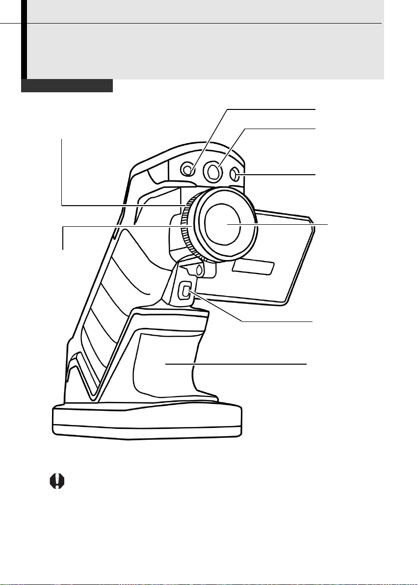
Front View
*Laser Pointer
Definable
*Illuminator
*Visual CCD
Focus Ring
Thermal
Lens Locking
Multi-function
*TIC-10 is not equipped with illuminator, visual CCD camera and laser pointer.
Component Guide
Ring
Camera
Lens
Trigger
Dock
Page 12
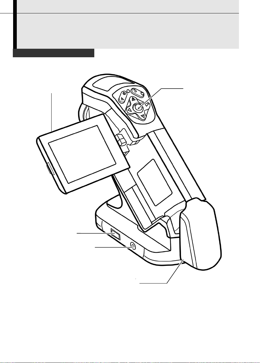
Back / Bottom View
Key Pad
LCD Display
Battery /SD Card Cover
USB Terminal
Video out
Terminal
Component Guide
11
Page 13
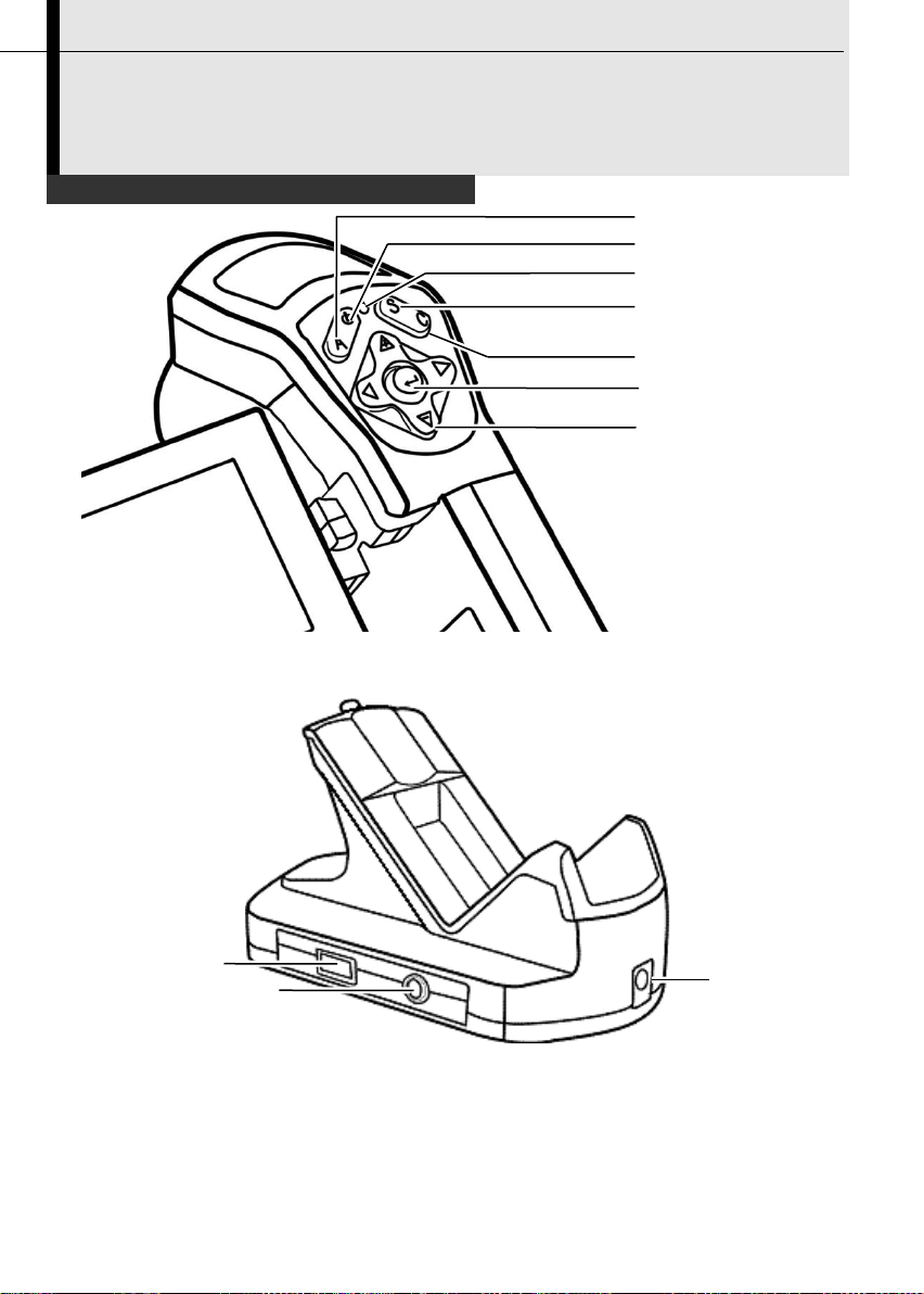
12
Controls / Multi-function Dock
Menu / Enter Key
Cursor Key
Cancel Key
Freeze / Activate
Power Switch
Auto Adjust Key
Power Indicator
USB
Terminal
Video Output
Power
Terminal
Component Guide
Terminal
Page 14
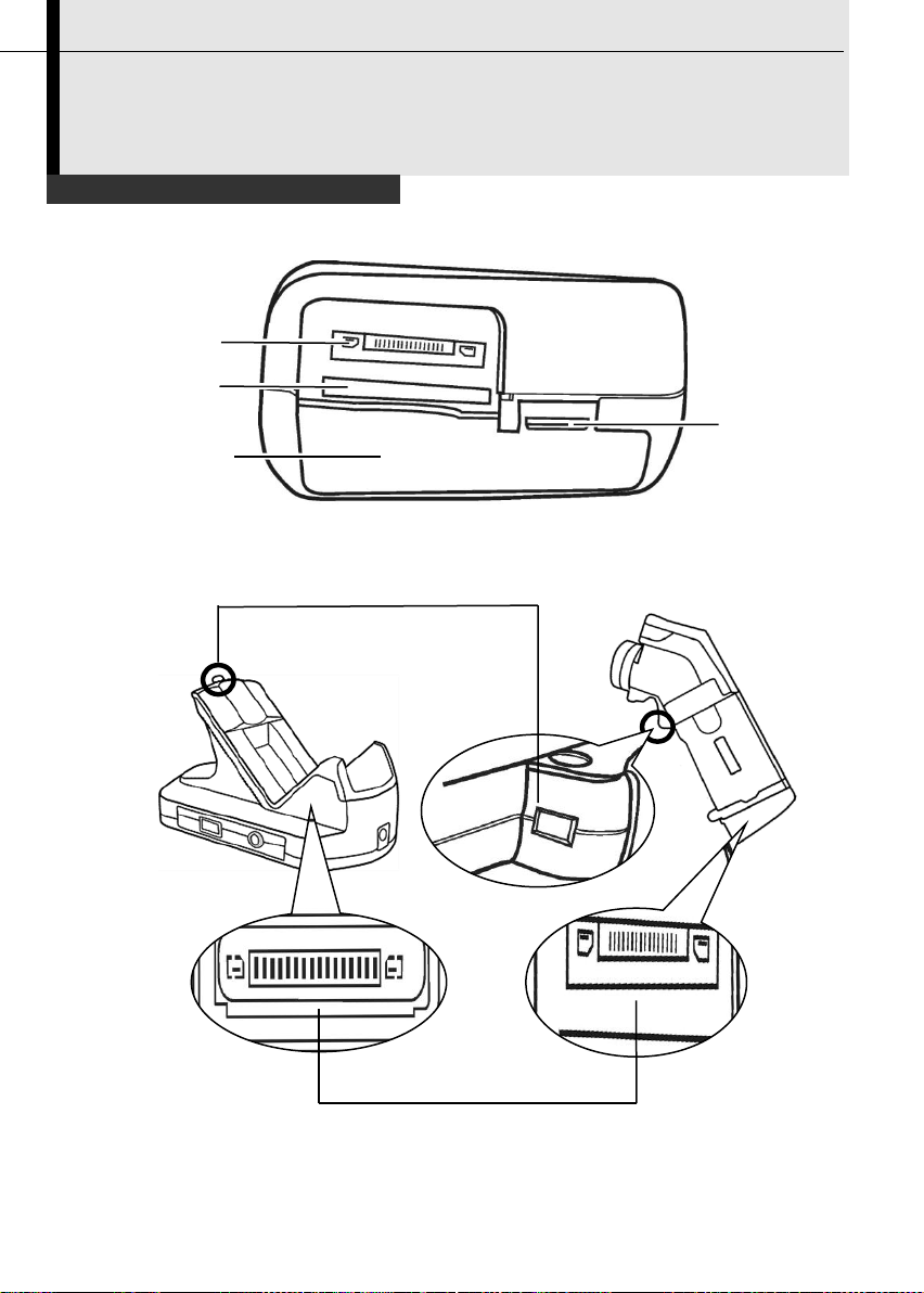
Bottom / Connectors
Lock
Battery Lock
SD Card Slot
Battery
insertion slot
Multi connector
Multi connector
Component Guide
13
Page 15
14
Charging the Battery Pack
1
Align the edge of the battery
pack with the line on the
battery, then insert the battery
in the direction of the arrow.
2
Attach the power cord to the battery charger and plug the other
end into a power outlet.
•
The charge indicator light is red while the battery pack is charging
and it turns green when charging is complete.
•
After charging, unplug the battery charger and remove the battery
pack.
•
This is a lithium ion battery pack so there is no need to discharge it
completely before recharging. It can be recharged at any time. However,
since the maximum number of charge cycle is approximately 300
(battery life), you are recommended to only charge the battery pack after
having discharge it completely to prolong battery life.
•
Charging times will vary according to the surrounding humidity and
battery pack charge state.
Preparing the IR Camera
Follow the steps below to charge the battery pack for the first time and
subsequently when the low battery icon appears on the Display Panel.
Page 16
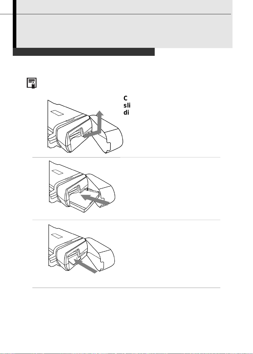
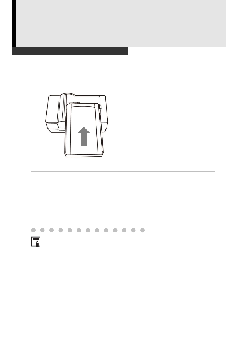
Installing the Battery Pack / SD Card
Charge the battery pack before using it for the first time.
1
Check if the power is off and
slide the battery cover in the
direction of the arrow.
2
Insert the battery pack.
Insert the battery in the
direction of the arrow.
3
Insert SD card.
Insert the SD card in the
direction of the arrow.
4
Close the battery / SD card cover.
Preparing the IR Camera
Install Battery Pack into the camera as follows,
15
Page 17

16
•
Remove the battery pack when the camera is not in use.
•
The SD Card must be formatted in FAT32. Otherwise, the IR camera
may not recognize the SD card.
Battery Status Symbols
The following icons indicate the battery status on the LCD display.
Sufficient battery charge
Low battery
Replace or recharge the battery
Page 18
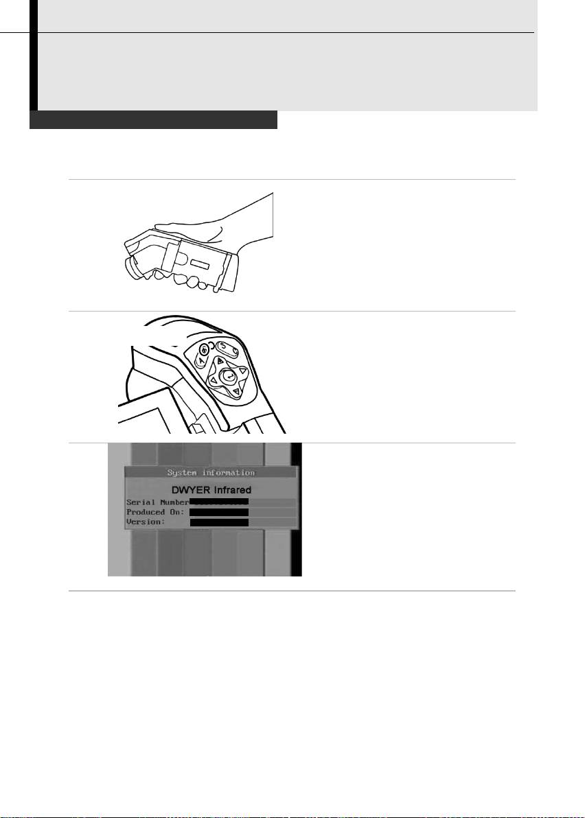
Turning the Power On / Off
1
Holding the camera correctly
with your right hand, put your
thumb above the key pad and
put your forefinger in front of
the definable trigger.
2
Press and hold the power
switch for 3 seconds.
•
The power indicator lights green.
3
After a while, a startup image
will appear on the screen.
4
Turn off the camera.
Hold the power switch for 3 seconds.
•
The power indicator goes off.
Power Switch
Preparing the IR Camera
The power indicator is lit while the power of the camera is on.
17
Page 19
18
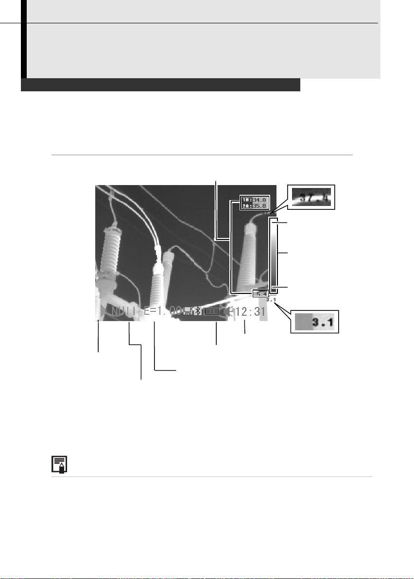
Checking the Information on the LCD Monitor
About the operation indicator
The operation indicator shows the current operation status of
the camera.
Upper limit of
Operation
Battery Charge
Time
Color
scale
Reading
Lower limit of
Activate
/ Freeze
Current
Max. temperature
Min. temperature
Preparing the IR Camera
The LCD monitor has a field of vision of 100% of the actual shooting
image.
The following displays in information view.
indicator
Emissivity
color scale
color scale
Page 20
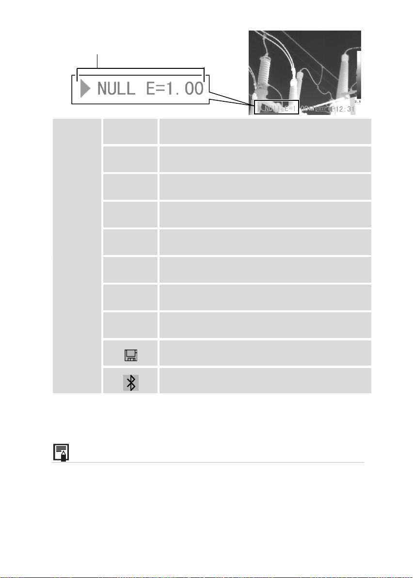
Status of
the
camera
Menu
Represents the menu mode.
Null
Represents the non-menu mode and no
analysis tools is selected.
*SP1…9
Represents the current analysis tool is
spot 1 or spot 2… or spot 9.
CAP.
Represents the current analysis tool is
auto-tracking spot.
*AR1…5
Represents the current analysis tool is
area 1 or area 2… or area 5.
*PRO.
Represents the current analysis tool is profile.
*ISO.
E
How to enter [Null] mode:
Press the cancel key repeatedly until you see the message of null in the
operation indicator.
Status of the camera
*The status varies according to different model of TIC series.
Before you make any further operation, please enter [Null] mode.
19
Page 21
20
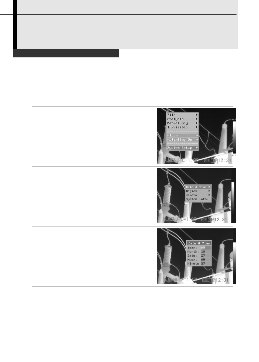
Setting the date and time
1
Make sure that the IR camera is in null mode.(p.19)
2
Press the MENU/ENTER key then
press the UP or DOWN arrow on
the omni selector to select the
[System Setup] menu.
3
Press the UP or DOWN arrow on the
omni selector to select [Date & Time]
then press the MENU/ENTER key.
4
Setting Date and Time
•
Press the UP or DOWN arrow on
the omni selector to select an item
to change.
•
Press the LEFT or RIGHT arrow on
the omni selector to set the values.
5
After adjusting the settings, press the MENU/ ENTER key to
save changes, or press the C key to go back to upper menu
without saving.
Preparing the IR Camera
You need to set the Date / Time when the IR camera is turned on for the
first time.
Page 22
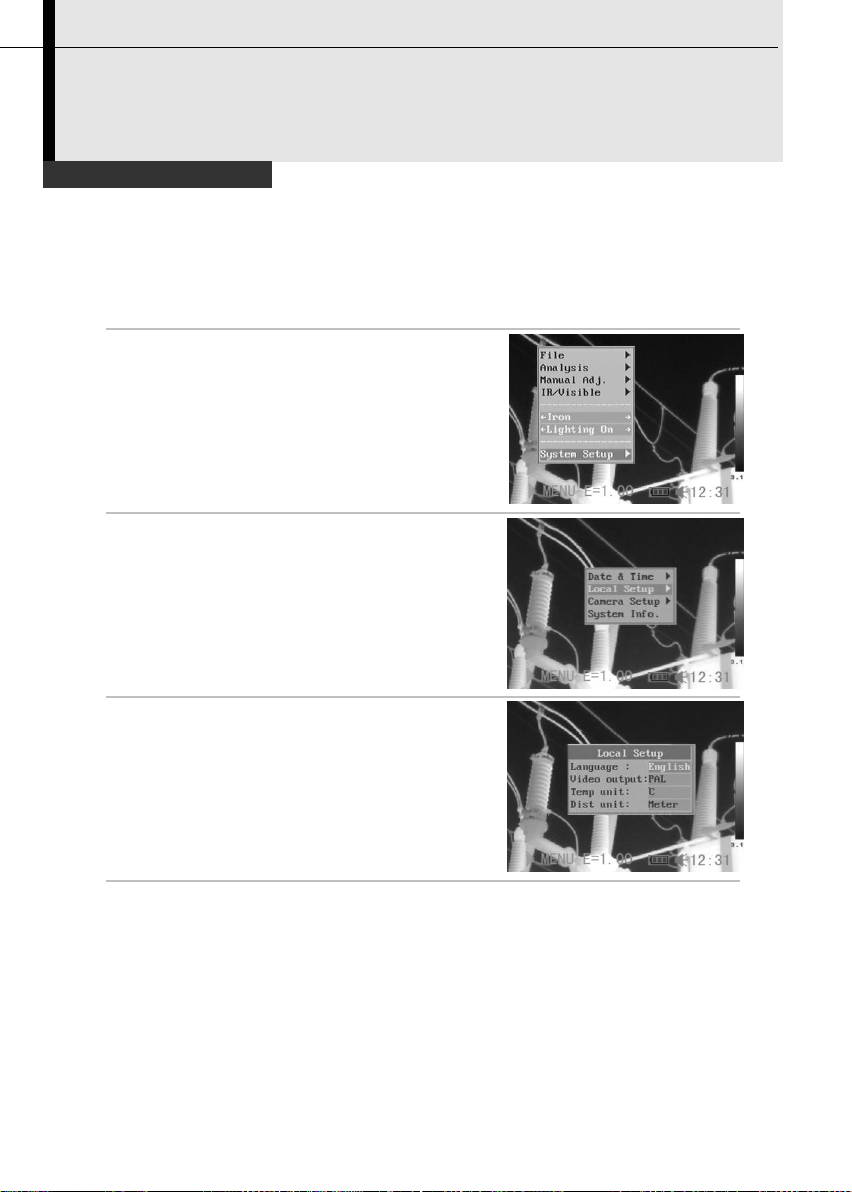
Local Settings
1
Make sure that the IR camera is in null mode.(p.19)
2
Press the MENU/ENTER key then
press the UP or DOWN arrow on
the omni selector to select the
[System Setup] menu.
3
Press the UP or DOWN arrow on the
omni selector to select [Local Setup]
then press the MENU/ENTER key.
4
Local Setup.
•
Press the UP or DOWN arrow on
the omni selector to select a field to
change.
•
Press the LEFT or RIGHT arrow on
the omni selector to set the values.
5
After adjusting the settings, press the Menu/ Enter key to
save changes, or press the C key to exit without saving.
Preparing the IR Camera
In this menu item, you can display the style of the built-in menu system.
21
Page 23

22
About the local settings
Language
Selects the language of the menus and
messages.
Video
output
Sets the format of the video output of the camera.
PAL or NTSC.
Temp unit
Sets the format of the displayed temperature unit
of the camera. °C or °F.
Distance
unit
Sets the format of the displayed distance unit of
the camera. Meter or Foot.
Page 24
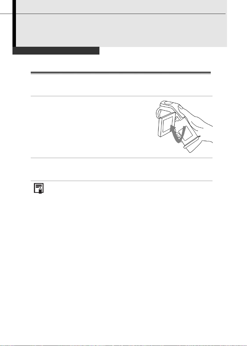
Using the LCD Monitor
Using the LCD Monitor
If you wish to use the LCD monitor for shooting, playing back
thermal images and adjusting menu settings, follow the
instructions below.
1
Open the LCD displayer in the
direction of the arrow.
2
Aim the IR camera at a subject.
1. For a better temperature measurement, please do make
the subject in center of the image that is shown on the LCD
monitor.
2. The LCD monitor will turn off when it is closed.
Basic Functions
23
Page 25
24
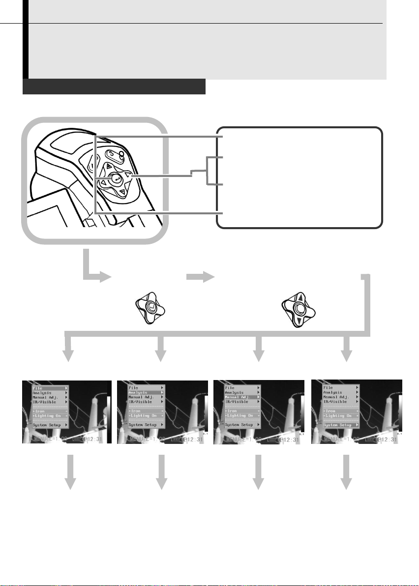
1
Press the MENU / ENTER
key.
2
Press the LEFT or RIGHT
arrow on the omni selector.
3
Press the UP or DOWN
arrow on the omni selector.
4
Press the MENU / ENTER
key.
Selecting Menus and Settings
1
2
File Menu
Analysis Menu
Manual Adjust
Setup Menu
Basic Functions
You can select the settings by pressing the MENU/ENTER key.
Menu
Select a function item using
Page 26

Displayed menu items will vary according to the operation and setting
contents.
*The menu items are different according to different type of camera.
4 Change the settings using
3 Select setting contents using
Exit
25
Page 27

26
Resetting the Settings to Default
1
Turn off the IR camera.(p.17)
2
Press and hold the power
switch and C key for seconds.
The data in storage will not be deleted when you reset the menu and
button operation settings to default.
Power switch
Cancel key
Basic Functions
You can reset the menu and button operation settings to default.
Page 28

IR Camera Adjustment
Manually Focus
1
Aim the IR camera at the
subject.
2
Turn the focus ring to focus on
the target.
3
Do not stop turning until the
image is clear.
Shooting
27
Page 29

28
IR Camera Adjustment
*DuoVision Display modes
Thermal, Visual and DuoVision image display
This IR camera records visual images with its built-in digital camera.
You can capture a visual image as a reference to the thermal image.
1
Press the MENU/ENTER key.
2
Press the MENU/ENTER key then
press the UP or DOWN arrow on the
omni selector to select the
[IR/Visible] menu.
3
IR/Visible Setup
•
Press the UP or DOWN arrow on
the omni selector to select an item
to change.
•
Press the LEFT or RIGHT arrow on
the omni selector to set the values.
4
Press UP or DOWN arrow on the omni selector to select
[Mode], and press LEFT or RIGHT to select a display mode,
then press MENU/ENTER key.
Shooting
Page 30

IR Camera Adjustment
IR only
In this mode, you can use the
analysis tools to analyze the target.
But what you see is the image with
pseudo color.
Vision Only
In this mode , you can see the image
with full color. But you can not use
any analysis tools to analyze the
target.
Duo Vision
In this mode, you can see the
background image is full color visible
image. And the thermal image “fuses”
on it in the center square. At the same
time you can use any analysis tools to
analyze the target.
In the IR and Vision Mix mode, you can press UP or DOWN arrow
to change the span(contrast) of the IR image and press LEFT or
RIGHT arrow to change the level(brightness).
Shooting
In DuoVision display mode, you can see
the thermal images “fuse” into the visible
images.
29
Page 31

30
Move the area up
C + UP
Move the area down
C + DOWN
Move the area left
C + LEFT
Move the area right
C + RIGHT
About the IR/Visible settings
IR
Percentage
Sets the ratio of IR images and Visual images. The
value is from 1% to 100%.
In DuoVision display mode, you can move the
fusion area via the combination keys.
Moving the fusion square
The items above are activated only in [Duo-Vision] mode.
Page 32

IR Camera Adjustment
Image adjustment
You can adjust the Level (brightness) and Span (contrast) of the
image captured by IR camera, manually or automatically.
Auto adjust
The IR camera will automatically adjust the brightness and / or
contrast and calibrate when you press the A key for the first time. If
you press A key a second time in 15 seconds, the camera will only
adjust brightness and / or contrast.
Shooting
31
Page 33
32
IR Camera Adjustment
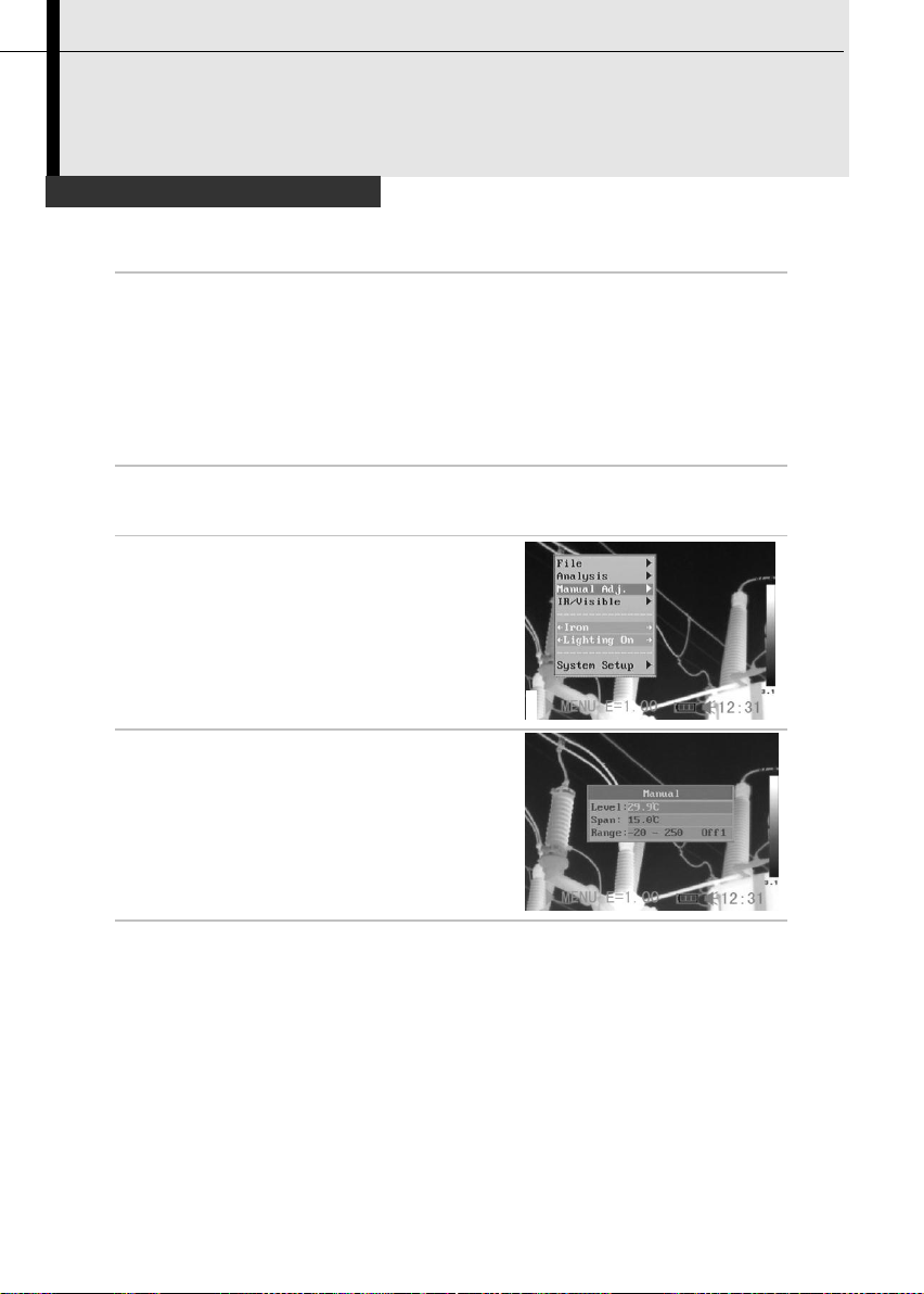
Manual adjust
You can adjust the Level and Span of the image manually in the
built-in menu system or by pressing arrows on the omni selector.
Press UP or DOWN arrow to change the span, and press LEFT
or RIGHT arrow to change the level.
Manual adjust in the menu
1
Press the MENU/ENTER key.
2
Press the UP or DOWN arrow on
the omni selector to select the
[Manual Adj.] menu.
3
Setting Level and Span.
•
Press the UP or DOWN arrow on
the omni selector to select an item
to change.
•
Press the RIGHT or LEFT arrow on
the omni selector to set the values.
4
After this operation, press the MENU/ENTER key to save
changes, or press the C key to go back to the upper menu
without saving.
Shooting
Page 34
IR Camera Adjustment
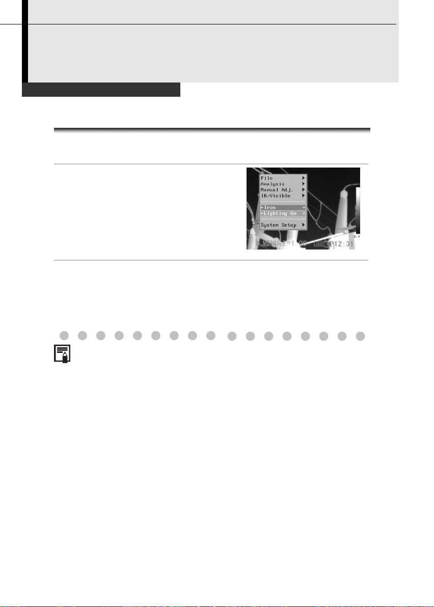
Palette settings
1
Press the MENU/ENTER key.
2
Press the UP or DOWN arrow on
the omni selector to select the
[Iron], press the LEFT or RIGHT
arrow to choose the palette.
3
After this operation, press the MENU/ENTER key to save
changes, or press the C key to close the menu without
saving.
The camera provides 6 kinds of palettes: Iron, Iron inverted, Rainbow,
Feather, Grey and Grey inverted.
Shooting
33
Page 35
34
IR Camera Adjustment
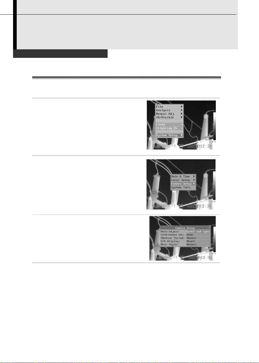
Image settings
1
Press the MENU/ENTER key.
2
Press the UP or DOWN arrow on
the omni selector to select the
[System Setup] menu, then
Press the MENU/ENTER key.
3
Press the UP or DOWN arrow on
the omni selector to select
[Camera Setup], then press the
MENU/ENTER key.
4
Set the Image Settings.
•
Press the UP or DOWN arrow on
the omni selector to select an item
to change.
•
Press the RIGHT or LEFT arrow on
the omni selector to set the values.
5
After this operation, press the MENU/ENTER key to save
changes, or press the C key to go back to the upper menu
without saving.
Shooting
Page 36

About the Image Settings
Auto adjust
Sets the function of A key.
Level
and
Span
The camera will automatically adjust the
level (brightness) and span (contrast) of
the image to the optimum setting.
Level
The camera will automatically adjust the
level (brightness) of the image.
Span
The camera will automatically adjust the
span (contrast) of the image.
Continuous
adj
Sets whether or not the brightness and contrast of
the image shown on the screen are adjusted
automatically
Level and span
The brightness and contrast is
adjusted automatically.
Level
The brightness is adjusted
automatically.
None
The brightness and contrast will
not be adjusted automatically.
Shutter
period
Sets the period of auto-adjusting.
LCD Display
Sets the period of shutting down the LCD Display.
Shut Down
Sets the period of shutting down the camera.
Laser Adjust
Adjusts the Laser point in the LCD displayer.
Menu Style
Sets the menu style.
35
Page 37

36
IR Camera Adjustment
Measurement range
Follow the below steps to change the measurement range.
1
Press the MENU/ENTER key.
2
Press UP or DOWN arrow on the
omni selector to select [Manual
Adj.], then press MENU/ENTER key.
3
Selecting measurement range for
different lens.
•
After selecting the [Range] field,
press UP and DOWN arrow on the
omni selector at the same time to
change the measurement range for
different lens( p.70).
4
After this operation, press the MENU/ENTER key to save the
changes or press the C key to go back to the upper menu
without saving.
Shooting
Page 38

IR Camera Adjustment
Freezing / Activating an image
You can activate / freeze a thermal image by pressing the S key
on the keypad.
1
Check that the IR camera is in null mode.(p.19)
2
Press the S key, then the image is
frozen.
3
Press the S key again, then the image is active.
Shooting
37
Page 39
38
Fulfill the Analysis Function
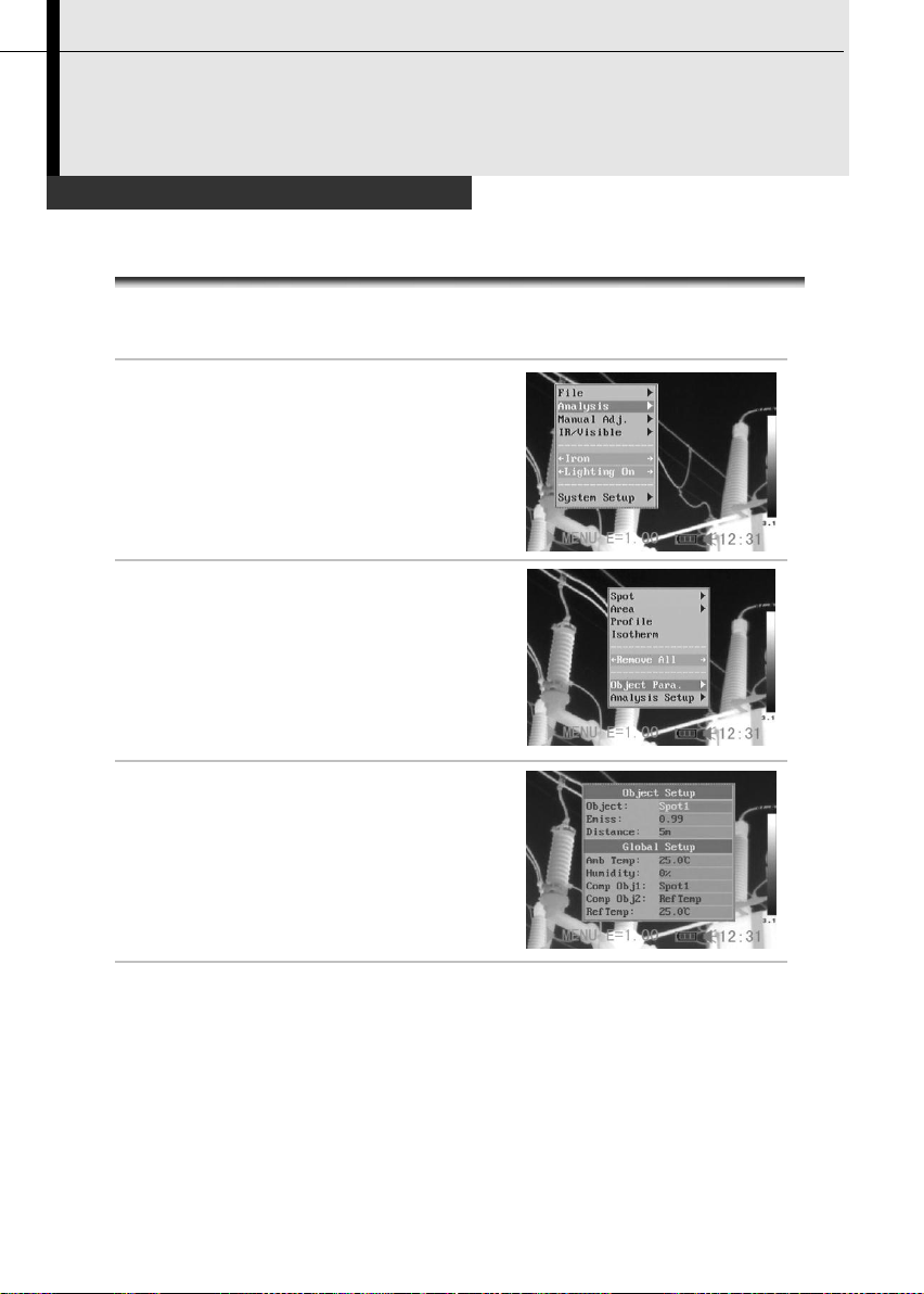
Setting object/global settings
1
Press the MENU/ENTER key.
2
Press UP or DOWN arrow on the
omni selector to select
[Analysis], then press the
MENU/ENTER key.
3
Press UP or DOWN arrow on
the omni selector to select
[Object Para.], then press the
MENU/ENTER key.
4
Setting analysis parameter.
•
Press the UP or DOWN arrow on
the omni selector to select an item
to change.
•
Press the LEFT or RIGHT arrow on
the omni selector to set the values.
5
After this operation, press the MENU/ENTER key to save
changes, or press the C key to go back to the upper menu
without saving.
Shooting
Page 40

About the analysis parameters
Object
Selects the object of which you want to set
the parameters.
Emiss
Different material has different emissivity.
Use different emissivity to measure different
material.
Distance
Different object has different distance to the
IR camera. Use different distance to
measure different object.
Amb Temp
Input ambient temperature.
Humidity
Input ambient humidity.
Comp Obj
Comp Obj1 can be set as any spot and
area; Comp Obj2 can be set as ref. temp.
and any spot and area. Differential of their
temperature will be showed at the right
bottom corner of the screen.
For example, Comp Obj1 is Spot 1(35.4℃)
and Comp Obj2 is Ref Temp(30℃), then
the final reading will be 5.4℃.
Ref Temp
Sets a reference temperature to compare
with the spot/area/profile tool.
The reading of Comp. Obj
Reading
39
Page 41
40
Fulfill the Analysis Function
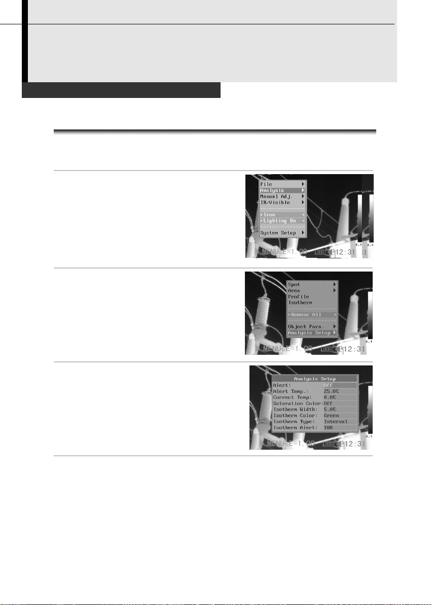
Setting analysis settings
1
Press the MENU/ENTER key.
2
Press the UP or DOWN arrow on
the omni selector to select the
[Analysis] menu, then press the
MENU/ENTER key.
3
Press UP or DOWN arrow on the
omni selector to select [Analysis
Setup], then press the
MENU/ENTER key.
4
Setting analysis parameter.
•
Press the UP or DOWN arrow on
the omni selector to select an item
to change.
•
Press the LEFT or RIGHT arrow on
the omni selector to set the values.
5
After this operation, press the MENU/ENTER key to save
changes, or press the C key to go back to the upper menu
without saving.
Shooting
Page 42

About the analysis settings
*Alert
There are two kinds of temp-alert:
Upper-limit alert and Lower-limit alert.
1.Upper-limit alert
Set item "alert" as [on], and "Capture spot" as
[maximum], then spot analysis tool "max sp10" will
automatically capture the hottest spot within the
screen, if this temperature is higher than the value
you set in "alert temp", the reading on top-right
screen will turn into RED,and a beeping sound will
be heard also.
2.Lower-limit alert
Set item "alert" as [on], and "Capture spot" as
[minimum], then spot analysis tool "mini sp10" will
automatically capture the coldest temperature
within the screen, if this temperature is lower than
the value you set in "alert temp", the reading on
top-right screen will turn into RED, and a beeping
sound will be heard also.
Note:select spot analysis tools [capture max.] &
[capture min.] in menu "Analysis".
*Alert Temp
Sets the temperature limit of “Alert”.
Correct
Temp
Corrects the measured temperature value of the
camera to ensure the measurement accuracy
under special circumstances.
Saturation
Color
When it’s on, Green will take place of the color that
stands for the highest temperature.
*Isotherm
Width
Sets the width of isothermal interval. The width can
be adjusted from 0.1℃ to the upper limit of the
maximum temperature measurement range under
this condition.
*Isotherm
Color
Sets the color of the isotherm interval. Transparent,
Green, Black and White are available.
41
Page 43

42
*Isotherm
Type
Sets the isothermal analysis mode. There are five
modes: Dual Above, Dual Below, Above, Below and
Interval.
Dual
Above
Display the isothermal interval in a
color and the parts with the higher
temperatures than the upper limit of
the isothermal interval in a different
color
Dual
Below
Display the isothermal interval in a
color and the parts with the lower
temperatures than the lower limit of
the isothermal interval in a different
color
Above
Display the isothermal interval and
the parts with the higher temperature
than the upper limit of the isothermal
interval in the same color
Below
Display the isothermal interval and
the parts with the lower temperature
than the lower limit of the isothermal
interval in the same color
Interval
Display the isothermal interval in one
color and all the other parts are
displayed in the normal pseudo color
mode
*Isotherm
Alert
The value is from 1 to 100, and it means 1/00 to
100/100 of the screen. For example, if the span of
isotherm is 35℃ to 40℃ and the isotherm alert is
50. If the proportion of isotherm area between 35℃
to 40℃ is over 50/100, alarm will ring.
Page 44

Fulfill the Analysis Function
Setting analysis tools
This topic briefly explains how to set the analysis tools on the thermal
image.
Spot analysis
1
Press the MENU/ENTER key.
2
Press the UP or DOWN arrow on the
omni selector to select the [Analysis]
menu.
3
Press the UP or DOWN arrow on the
omni selector to select the [Spot]
menu.
4
Setting the spot analysis.
•
Press the UP or DOWN arrow on the omni
selector to select a spot, then press
MENU/ ENTER Key.
•
Spot 10 will automatically track the hottest
and coldest temperature spot within an
area of which the shape and size can be
set by the user(p.46). Press LEFT or
RIGHT to select the Maximum spot or
Minimum spot.
Shooting
43
Page 45

44
5
Moving the spot.
•
Start from Step 1 to set or select a spot a
analysis spot.
•
Press the UP, DOWN, LEFT, RIGHT arrow
on the omni selector to move the activated
spot.
•
Press Menu/Enter key to fix the position of
the spot.
Temperature reading of spot
changes in real-time.
6
Removing the spot
•
Start from Step 1 to set or select an analysis spot.
•
Press C key to remove the spot.
Spot NO.
Temperature
reading
Page 46

Fulfill the Analysis Function
*Area analysis
1
Press the MENU/ENTER key.
2
Press the UP or DOWN arrow on the
omni selector to select the [Analysis]
menu.
3
Press the UP or DOWN arrow on the
omni selector to select the [Area]
menu.
4
Setting the analysis area.
•
Press the UP or DOWN arrow on the omni
selector to select an area, then press
MENU/ ENTER Key. One or more boxes
will appear on the screen.
•
A reading will appear at the top right
corner. It is the reading of the
highest/lowest/average temperature of the
current area.
•
H is short for highest temperature, L for
lowest temperature, and A for average
temperature.
•
Press LEFT or RIGHT to select to show
the Maximum or Minimum or Average
temperature of the area.
•
If Area 5 is selected, Maximum and
Minimum and Average temperature of it
will appear at the same time.
Shooting
45
Page 47

46
5
Moving the area.
•
Start from Step 1 to set or select an area
analysis.
•
Press the UP, DOWN, LEFT, RIGHT arrow
on the omni selector to move the activated
area.
Temperature reading changes in
real-time.
6
Removing the area
•
Start from Step 1 to set or select an area analysis.
•
Press C key to remove the activated area.
About changing the shape of the analysis area
UPPER and LEFT arrow
UPPER and RIGHT arrow
LOWER and LEFT arrow
LOWER and RIGHT arrow
Area NO.
Readings
Page 48
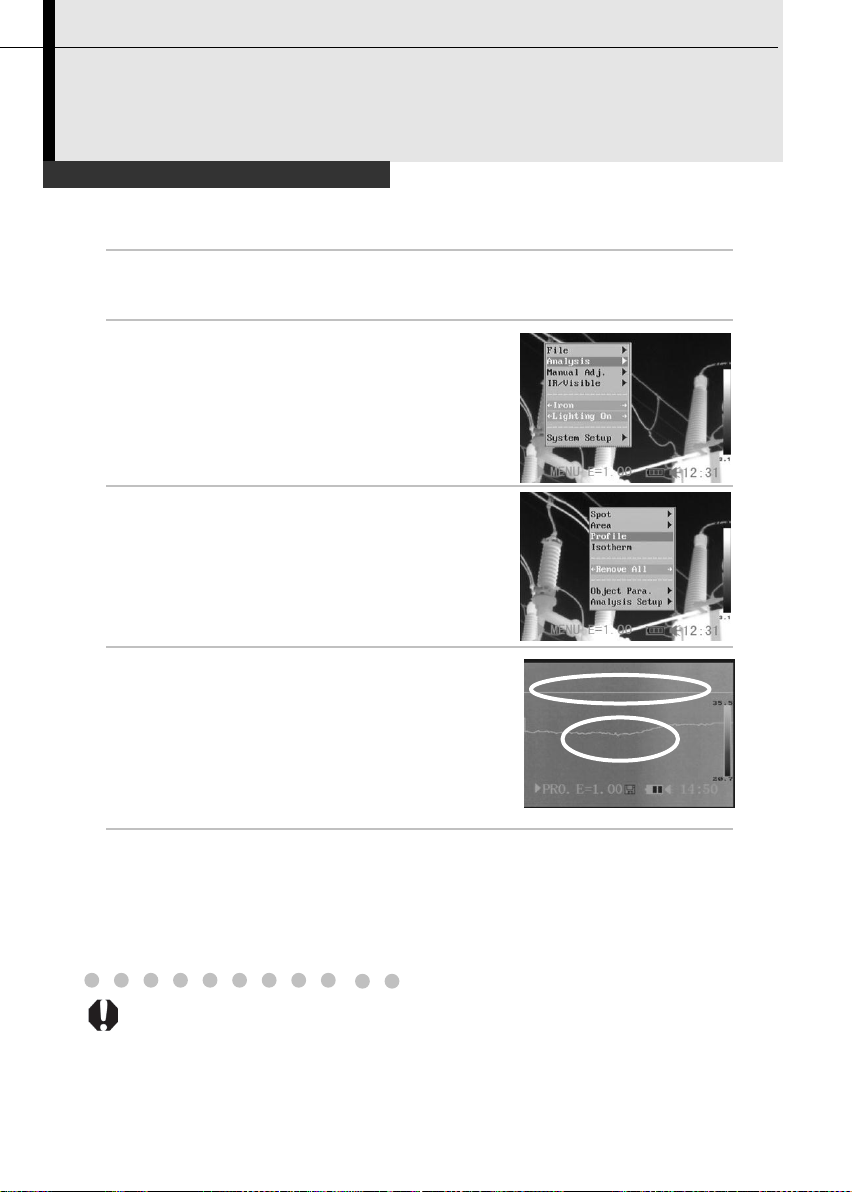
Fulfill the Analysis Function
*Profile analysis
1
Press the MENU/ENTER key.
2
Press the UP or DOWN arrow
on the omni selector to select
the [Analysis] menu.
3
Press UP and DOWN arrow on
the omni selector to select
[Profile], then press the
Menu/Enter key. A profile
will appear on the screen.
4
Moving the profile analysis.
•
Start from Step 1 to set or select a
profile analysis.
•
Press the UP, DOWN arrow on the
omni selector to move the profile.
5
Removing the profile analysis.
•
Start from Step 1 to set or select a profile analysis.
•
Press C key to remove the activated profile.
Temperature
distribution
Shooting
47
Page 49

48
Fulfill the Analysis Function
*Isotherm analysis
1
Press the MENU/ENTER key.
2
Press the UP or DOWN arrow on the
omni selector to select the
[Analysis] menu.
3
Press UP or DOWN arrow to select
[Isotherm], then press the
Menu/Enter key. Areas of concern
will be highlighted with color.
4
Setting isotherm range.
•
Start from Step 1 to set or select
isotherm analysis.
•
Press the UP or DOWN arrow on the
omni selector to select isotherm
range.
•
IL and IH will appear at the bottom
right corner. It is the high limit (IH) and
low limit (IL) of the isotherm range.
Shooting
Page 50
Fulfill the Analysis Function
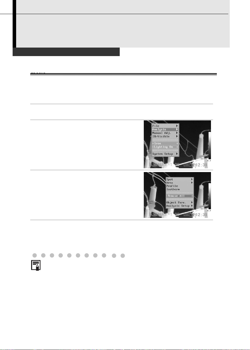
Remove analysis tools
this
This topic briefly explains how to remove analysis tools you place
on the screen.
Remove analysis tools
1
Press the MENU/ENTER key.
2
Press the UP or DOWN arrow on
the omni selector to select the
[Analysis] menu.
3
Press the UP or DOWN arrow on
the omni selector to select
[Remove Spot].
•
Press the LEFT or RIGHT arrow on
the omni selector to select to remove
all the spots/areas/profile or remove
all the analysis tools
4
Press the MENU/ENTER key to remove all the spots.
Shooting
49
Page 51

50
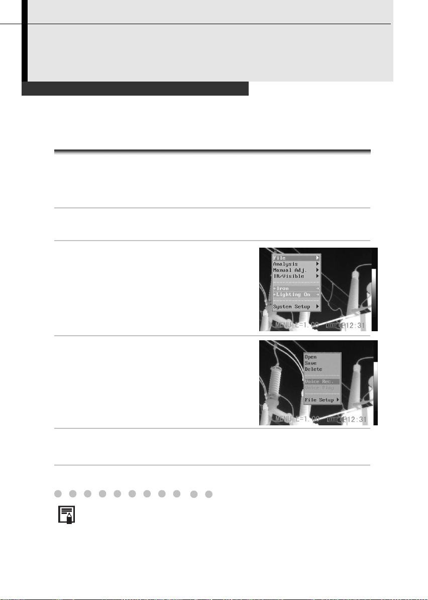
Saving the Image
1
Press the MENU/ENTER key.
2
Press the UP or DOWN arrow on the
omni selector to select the [File]
menu.
3
Press UP or DOWN arrow on the
omni selector to select [Save], then
press the Menu/Enter key to save
the image.
The display mode decides the
save image type.(p.28)
4
The name of saving image will be
displayed on the screen.
Shooting
You can save the image in the menu system after you freeze an
image (p.37), or save it directly by holding the S key on the omni
selector for 3 seconds without freezing an image.
Page 52
Attaching Voice Memos to Images
Voice recording
1
Install the Bluetooth (optional) headset.
2
Freeze an image (p.37), then press the MENU/ENTER key.
3
Press the UP or DOWN arrow on the
omni selector to select the [File]
menu.
4
Press UP or DOWN arrow on the
omni selector to select [Voice REC.],
then press the Menu/Enter key.
•
The [Voice Recording] message will
appear on the LCD monitor.
5
Speak toward the microphone of the headset. To stop
recording, press the C key.
6
Save the image (p.50).
The storage capacity of the memory will not decrease when you
attach voice comment to an image.
Shooting
You can introduce an image with voice recording. Only TIC-30 has this
function.
51
Page 53

52
Setting the Trigger
Setting definable trigger
1
Press the MENU/ENTER key.
2
Press the UP or DOWN arrow on the
omni selector to select [Lighter On].
•
Press the LEFT or RIGHT arrow on
the omni selector to select Lighter
On/Save File/Laser On/ Freeze Live.
About the function of definable trigger
*Lighting on
You can activate the illuminator by pressing the
trigger.
You can get clear visible images in darkness
when you turn on the illuminator.
Save File
Save the image by pressing the trigger for 3
seconds.
*Laser on
You can activate the laser pointer by pressing the
trigger.
Do not trigger the laser pointer in human or animal
eyes. Exposure to the laser produced by the laser
pointer may damage eyesight.
Freeze/Live
Freeze or activate an image.
Auto adjust
Automatically adjust the brightness and contrast.
Shooting
You can set the definable trigger with different function, such as saving
image, laser and turning on the illuminator.
*TIC-10 is not equipped with laser and illuminator.
Page 54

Opening Images
1
Press the MENU/ENTER key.
2
Press the UP or DOWN arrow on the
omni selector to select the [File]
menu.
3
Press UP or DOWN arrow on the
omni selector to select [Open], then
press the MENU/ENTER key.
4
Press LEFT or RIGHT arrow on the
omni selector to select an image,
then press MENU/ENTER key to
open it. How to select an image,
refer to (p.54).
You can analyze and attach voice memo to a recorded image when you
open it.
You can press the A, C and S key together to set the folder name to
sat00001.
Playback and Erase
You can view and analyze the recorded images on the LCD monitor.
53
Page 55
54
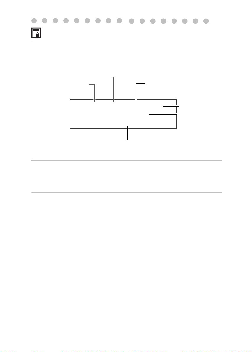
How to select an image
1
After you select [Open] or [Delete] option under [File] menu, a
message shown as below will appear in the bottom-left
screen.
2
If the image you wish to open or delete is not in the current
folder, press the [LEFT] or [RIGHT]arrow on the omni selector
repeatly to select the image.
3
Press the S key, you can activate the image.
00001/00003/002/003
<DIR> GZSAT001
Open SAT00001.SAT
File Name
Folder amount
Serial number of
current folder
File amount
of current folder
Serial number
of current file
Current folder
Page 56

Selecting the folder and filename
1
Press the MENU/ENTER key.
2
Press the UP or DOWN arrow
on the omni selector to select
the [File] menu, then press the
MENU/ENTER key.
3
Press the UP or DOWN arrow
on the omni selector to select
the [File Setup] menu, then
press the MENU/ENTER key.
4
Press the UP or DOWN arrow
on the omni selector to select
the [Directory Name] menu,
then press the LEFT or RIGHT
arrow to select the folder. [File
number] is the number of file
in current folder.
5
Press the UP or DOWN arrow on the omni selector to
select the [File Name] menu, then press the LEFT or
RIGHT arrow to select the filename.
55
Page 57

56
Playback Memos
1
Bind the *Bluetooth
headset (optional, p.67).
2
Open an image, refer to
(p.53).
3
Press MENU/ENTER key then
press UP or DOWN arrow on the
omni selector to select the [File]
menu.
4
Press UP or DOWN arrow on the
omni selector to select [Voice
Play], then press the Menu/Enter
key.
•
A [Playing Record] message will
appear on the LCD monitor.
5
You can terminate the playback of voice comment by
pressing the C key.
Playback and Erase
You can playback voice comment of an image when you attached a voice
comment with it.
*Bluetooth is only for TIC-30.
Page 58

Erasing Images
Please note that erased images cannot be recovered.
Exercise caution before erasing an image.
1
Press MENU/ENTER key then
press UP or DOWN arrow on the
omni selector to select the [File]
menu.
2
Press UP or DOWN arrow on the
omni selector to select [Delete],
then press the MENU/ENTER key.
3
Select an image, refer to (p.54),
then press MENU/ENTER key to
delete the selected image.
4
Press the C key to exit.
Playback and Erase
57
Page 59
58
Download the images via SD card
1
Open the battery / SD card cover.
2
Press the SD card lightly, then the
SD card will pop-up automatically.
3
You can download the IR images via the supplied SD
card reader.
Download the Images
You can get the SD card out of camera, and download the images to the
computer via the supplied SD card reader.
Page 60

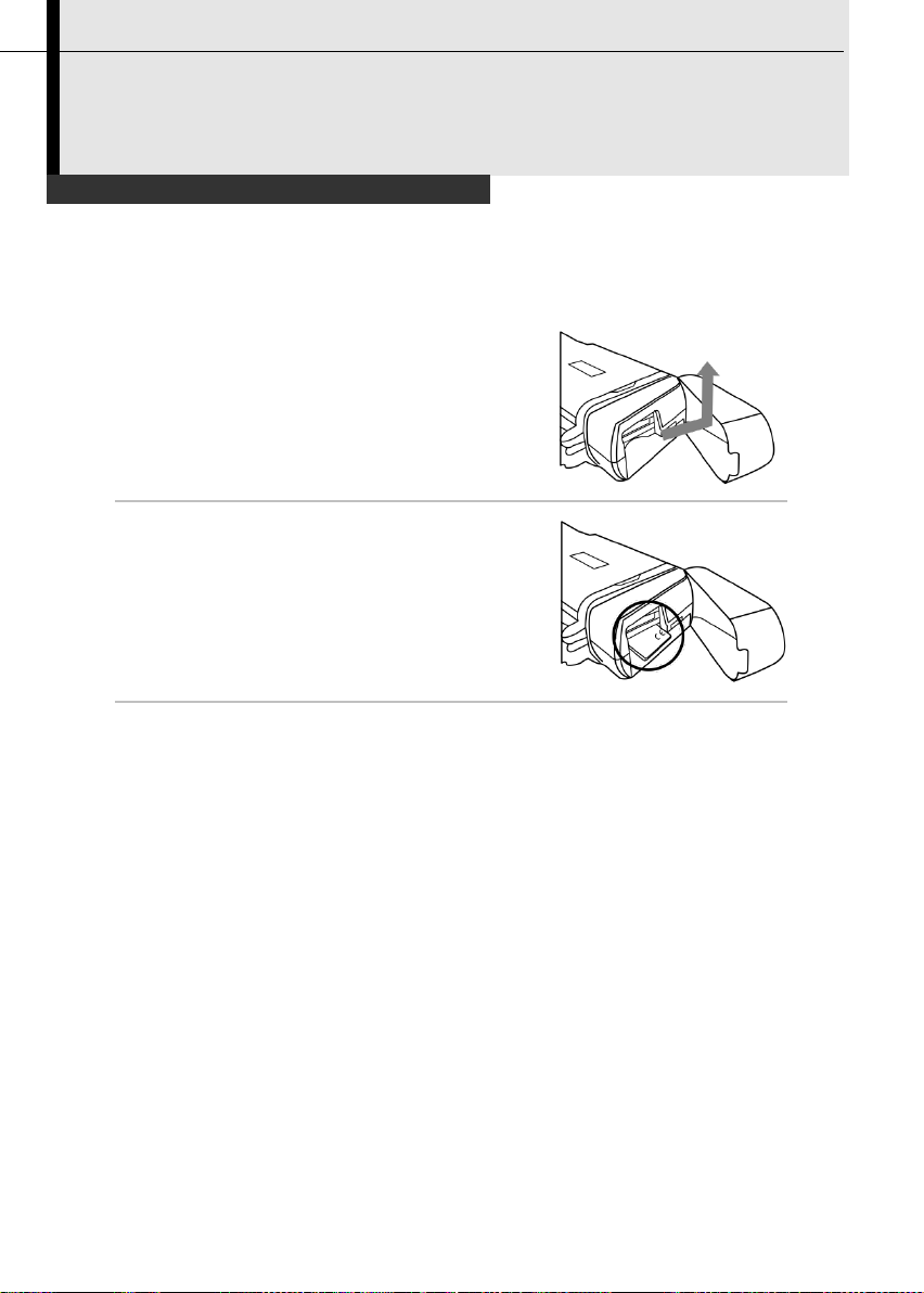
Connecting the dock
1
Open the battery/SD card cover
in the direction of the arrow.
2
Lay the dock on a horizontal
surface, then put the camera on
the dock in the direction of the
arrow.
Press the camera
gently down to the
dock in the direction of
the flute in the dock.
3
Now you can use the multi-functional dock.
Connection and Download
You can transmit real-time IR video and charge the battery, when you
connect between IR camera and multi-functional dock.
59
Page 61

60
Charging via the dock
1
Attach power adaptor to the power terminal on the
multi-functional dock.
2
3
Attach the power cord to the dock and plug the other end into a
power outlet.
4
•
The power LED of camera flickers while the battery pack is charging
and it lights green when charging is complete.
•
Unplug the power adaptor from the power outlet, after charging.
Connection and Download
You can charge the battery via the supplied power adaptor.
Page 62

Connecting to a monitor
1
Attach video cable to the video out
terminal on the multi-functional
dock.
2
Plug the other end of the video
cable to the video in jack on the
monitor.
To the
video in jack
Connection and Download
A video-compatible monitor connected via the video cable (supplied)
can be used to view and analyze images you shoot.
61
Page 63

62
Connecting to a computer
Connection
Connect the USB cable (optional) to the computer’s USB port and
the multi-functional dock’s terminal. Only TIC-30 has the USB
function.
•
You do not need to turn off the computer or camera when
making this connection.
•
Please refer to your computer manual for information regarding
the location of the USB port
The USB port can only be used with optional real-time software.
USB CABLE
USB PORT
DOCK
Connection and Download
Page 64
Real-time transfer
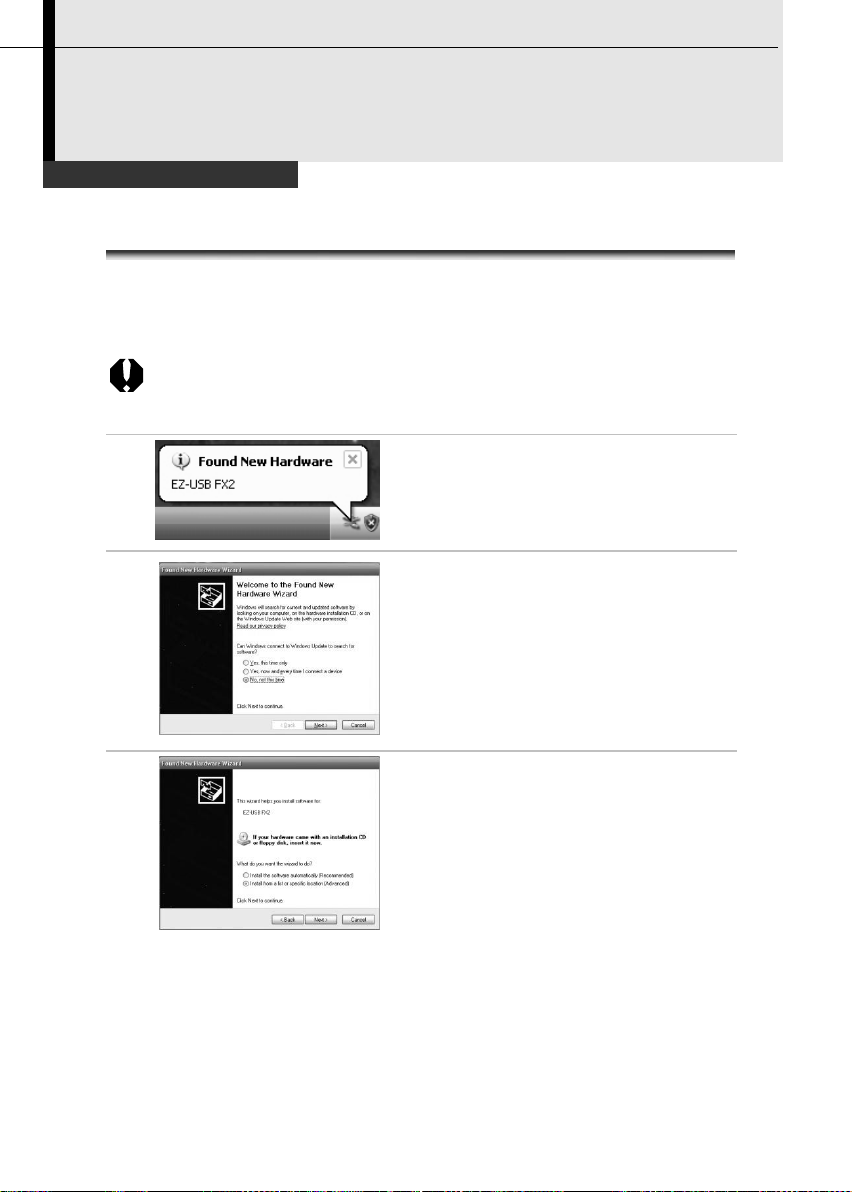
Installing the driver
Users of Windows XP Professional must first log in as an Administrator
(computer system administrator) to install program.
1
After a few moments, the following
dialog will appear.
2
Select [No, not this time] then click
[Next >].
3
Select [Install from a list or location
(Advanced)] then click [Next >].
Connection and Download
63
Page 65

64
4
Select [Include this location in the
search] then click [browse]. Locate
the directory of the driver, and click
[Ok] to return to the previous
window. Then click [Next >].
5
Click [Continue Anyway].
6
Click [Finish] to finish the driver
installation.
Page 66
1
Power on the camera, connect the camera and the dock, p.59.
2
Connect the dock and computer via USB cable (optional).
3
The operation system will recognize the camera after install
the driver.
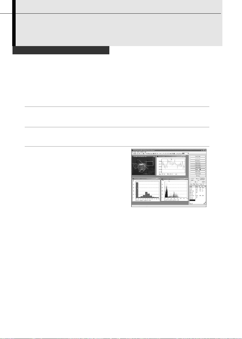
4
You can analyze the real-time
video, and save it in your
computer’s disk.
Transfer Video via USB
Connection and Download
You can analyze and save the thermal video in computer directly via the
USB by the optional real-time software.
65
Page 67

66
Real-time transfer
Troubles shooting
Connection and Download
First, Check the Following
1. Does your computer comply with these requirements?
Ensure the system has a built-in USB port and it comes with
Windows XP preinstalled.
The USB interface is not supported for systems not complying
with the above conditions.
2. Is the camera correctly connected to the computer?
See Page 62 for connection instructions.
3. Is the battery charged sufficiently?
You should use a household power source to power the camera
• If the Problem Is Not Mentioned Above
If the USB Driver is not correctly installed, it is possible that Windows is not
recognizing the USB Driver. Please contact your motherboard’s
manufacturer for the latest driver.
The USB2.0 real-time transmission function may not properly work under
some model of motherboard’s chipset. In this case, connect the IR camera
to another computer which is based on the chipset of Intel configuration
or NVidia configuration and try again.
when it is connected to a computer.
Page 68

1
Turn off the camera and Bluetooth headset.
2
Turn on the Bluetooth headset
first.
Press and hold the power button
about 4 seconds. And then you
can see the power indicator
begins to blink red and blue. The
headset is in pairing status in 90
seconds.
3
Turn on the camera.
You can see the green indicator
of camera lights and the blue
indicator flashes at the same
time. In this mode, camera is
preparing to pair the Bluetooth
headset.
4
Press the power button of Bluetooth headset to pair the
headset and camera. When the pairing is successful,
blue indicator of the headset flashes slowly.
Then you can see the Bluetooth icon on the
middle-bottom screen, p.19.
Make sure that the camera is not too far from the Bluetooth
headset. If possible, try to take the Bluetooth headset
closer to the camera in step 4.
Use the *Bluetooth headset
The power
button and
the power
Connection and Download
Follow the steps to install the Bluetooth headset (optional) first time.
indicator.
67
Page 69

68
5
After pairing the camera and
headset first time. In next time,
turn on the headset to check
the power indicator blinks blue,
and then turn on the camera,
you can use it.
Press C key and Enter key
together to free the Bluetooth
headset.
6
Wear the headset, you can record the voice memos
(p.51) or play back the memos (p.56).
*Bluetooth headset is not the standard accessory of TIC-10 and
TIC-20. The picture is for reference and the sample is subject to the
real product which you will receive.
Page 70
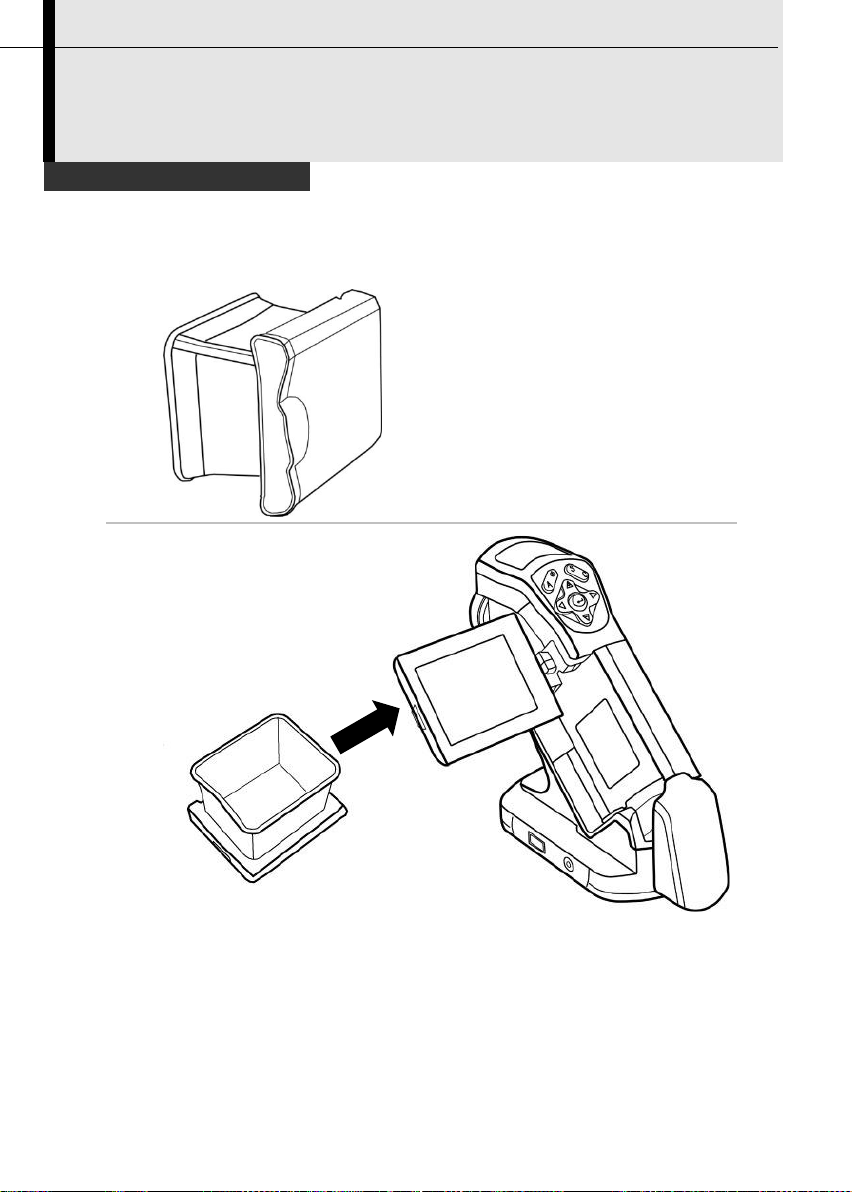
1
Install the sun shield in the
direction of the arrow by
following the below guide.
2
Use the sun shield
Accessory
You will see more clearly with sun shield when you are shooting outdoors
in the sun.
69
Page 71

70
1
Loosen the standard lens, and screw the optional lens as
follow.
2
Set up the measurement
range. Press UP and Down
key on the arrow at the same
time to change to type of
lens. (p.36).
Refer to the below table to
see what type of lens the
letter stands for.
Type
Null A B C D
E
Lens
20°
12.8°
38°
3.8°
6.4°
9°
Use the optional lens
Accessory
There are 5 optional lenses for the TIC series. You can change the lens
as follow.
Page 72

Problem
Cause
Solution
Camera will
not operate
Power is not turned on
• Turn on the camera. See
Turning the Power On / Off
(p.17).
Insufficient battery voltage
• Fully charge the battery.
Poor contact between
camera and battery terminals
• Wipe the terminals with a clean,
dry cloth.
Camera will
not record
Internal memory is full
• If required, download the
images to a computer and
erase them to make some
space.
Internal memory not
formatted correctly
• Format the internal memory in
FAT32 format.
Battery pack
consumed
quickly
Battery pack capacity
reduced because of disuse
for one year or more after
being fully charged.
• Replace the battery pack with a
new one.
Battery life exceeded
• Replace the battery pack with a
new one
Battery pack
will not
charge
Poor contact between
battery pack and battery
charger.
• Clean the battery terminals with
clean cloth.
• Connect the power cord to the
battery charger and insert its
plug firmly into the power outlet.
Battery life exceeded
• Replace the battery pack with a
new one.
Trouble Shooting
71
Page 73

72
Camera Care and Maintenance
Camera Body
Wipe the body clean with soft cloth or eyeglass
lens wiper.
Lens
First use a lens blower to remove dust and dirt,
then remove any remaining dirt by wiping the lens
lightly with soft cloth.
•
Never use synthetic cleaners on the camera body or
lens.
LCD monitor
Use a lens blower brush to remove dust and dirt. If
necessary, gently wipe the LCD monitor with soft
cloth or an eyeglass lens wiper to remove stubborn
dirt.
•
Never rub or press forcefully on the LCD monitor.
These actions may damage it or lead to other
problems.
Never use thinners, benzene, synthetic cleaners or water to clean the
camera. These substances may distort or damage the equipment.
Appendix
Use the following procedures to clean the camera body, lens, LCD
monitor and other parts.
Page 74

Emissivity table
Material
Temperature(°C )
Emissivity
approximation
Metal
Aluminum
Polished aluminum
100
0.09
Commercial aluminum
foil
100
0.09
Electrolytic
chromeplate alumina
25~600
0.55
Mild alumina
25~600
0.10~0.20
Strong alumina
25~600
0.30~0.40
Brass
Brass mirror (highly
polished)
28
0.03
Brass oxide
200~600
0.61~0.59
Chrome
Polished chrome
40~1090
0.08~0.36
Copper
Copper mirror
100
0.05
Strong copper oxide
25
0.078
Cuprous oxide
800~1100
0.66~0.54
Liquid copper
1080~1280
0.16~0.13
Gold
Gold mirror
230~630
0.02
Appendix
73
Page 75

74
Emissivity table (continue)
Material
Temperature(°C )
Emissivity
approximation
Iron
Polished cast iron
200
0.21
Processed cast iron
20
0.44
Polished tempered
iron
40~250
0.28
Polished steel ingot
770~1040
0.52~0.56
Raw welded steel
945~1100
0.52~0.61
Surface ferric oxide
20
0.69
Completely rusty
surface
22
0.66
Rolled iron plate
100
0.74
Oxidized steel
198~600
0.64~0.78
Cast iron (Oxidizing at
600°C )
198~600
0.79
Steel (Oxidizing at
600°C )
125~520
0.78~0.82
Electrolytic ferric
oxide
500~1200
0.85~0.89
Iron plate
925~1120
0.87~0.95
Cast iron, heavy ferric
oxide
25
0.80
Tempered iron, ferric
oxide
40~250
0.95
Melting surface
22
0.94
Melting cast iron
1300~1400
0.29
Melting mild steel
1600~1800
0.28
Liquid steel
1500~1650
0.42~0.53
Pure liquid iron
1515~1680
0.42~0.45
Appendix
Page 76

Emissivity table (continue)
Material
Temperature(°C )
Emissivity
approximation
Lead
Pure lead (Nonoxidization)
125~225
0.06~0.08
Mildly oxidized
25~300
0.20~0.45
Magnesium
Magnesia
275~825
0.55~0.20
Magnesia
900~1670
0.20
Hg
0~100
0.09~0.12
Nickel
Electroplate polishing
25
0.05
Electroplate
20
0.01
non-polishing
Nickel wire
185~1010
0.09~0.19
Nickel plate (oxidized)
198~600
0.37~0.48
Nickel oxide
650~1255
0.59~0.86
Nickel alloy
Nickel-chrome (heatresistance) alloy wire
(shining)
50~1000
0.65~0.79
Nickel-chrome alloy
50~1040
0.64~0.76
Nickel-chrome (heat
resistance)
50~500
0.95~0.98
Nickel-silver alloy
100
0.14
Silver
Polished silver
100
0.05
Appendix
75
Page 77

76
Emissivity table (continue)
Material
Temperature(°C )
Emissivity
approximation
Stainless steel
18-8
25
0.16
304(8Cr,18Ni)
215~490
0.44~0.36
310(25Cr,20Ni)
215~520
0.90~0.97
Tin
Commercial tin plate
100
0.07
Strong oxidization
0~200
0.60
Zinc
Oxidizing at 400°C
400
0.01
galvanized shining
iron plate
28
0.23
Ash zinc oxide
25
0.28
Non-metal materials
Brick
1100
0.75
Fire brick
1100
0.75
Graphite (lamp black)
96~225
0.95
Porcelain enamel
(white)
18
0.90
Asphaltum
0~200
0.85
Glass (surface)
23
0.94
Heat-resistance glass
200~540
0.85~0.95
Calcimine
20
0.90
Oak
20
0.90
Appendix
Page 78

Emissivity table (continue)
Material
Temperature(°C )
Emissivity
approximation
Carbon piece
0.85
Isolation piece
0.91~0.94
Sheet metal
0.88~0.90
Glass pipe
0.90
Loop type
0.87
Porcelain enamel
products
0.90
Porcelain enamel
designs
0.83~0.95
Solid materials
0.80~0.93
Ceramics (vase type)
0.90
Film
0.90~0.93
Mica
0.94~0.95
Flume mica
0.90~0.93
Glass
0.91~0.92
Semiconductor
0.80~0.90
Transistor (plastics
sealed)
0.30~0.40
Transistor (metal)
Diode
0.89~0.90
Transmitting loop
Pulse transmission
0.91~0.92
Level chalkiness layer
0.88~0.93
Top loop
0.91~0.92
Appendix
77
Page 79

78
Emissivity table (continue)
Material
Temperature(°C )
Emissivity
approximation
Electric materials
Epoxy glass plate
0.86
Epoxy
hydroxybenzene plate
0.80
Gilded sheet copper
0.30
Solder-coated copper
0.35
Tin-coated lead wire
0.28
Brass wires
0.87~0.88
Block talcum terminal
0.87
Appendix
Page 80

Model
TIC-10
TIC-20
TIC-30
Imaging Performance
Field Of View/Mini.
Focus Distance
20° x15°/0.1m
Thermal
Sensitivity(N.E.T.D)
0.1°C@30°C
Detector Type
Focal Plane Array (FPA), uncooled microbolometer
IR Resolution
160 x120
Spectral Range
8-14um
Focus Mechanism
Manual Focusing
I.F.O.V(With Standard
Lens)
2.2 mrad
Image Presentation
Image Modes
Thermal
Thermal/Visible
/DuoVision
Thermal/Visible
/DuoVision
Fusion
No
Yes
Yes
Image Annotation
No
No
Voice
Annotation
Display
2.5” TFT Screen
Visible Light Camera
Resolution
640 x 480 Full-color
Measurement
Temperature Range
-20°C~250 °C
Accuracy
±2°C Or ±2% Of Reading
Measurement Modes
/Analysis tools
1 movable spot,
auto hot/cold
spot, Δt
4 movable spots,
auto hot/cold spot,
isotherm, Δt
9 movable spots,
auto hot/cold spot,
profile, area box,
isotherm, Δt
Temperature Alarms
No
Yes
Yes
Set-up Controls
Language/Date And Time Format/Palettes/Units
Measurement
Corrections
Ambient Temperature/ Emissivity Correction/
Distance/ Humidity
Storage
Specification
All data is based on Dwyer’s testing standard. Subject to change without
notice.
79
Page 81

80
Storage Type/Capacity
SD Card/2 GB Removable, Up to 16G
Formats
.SAT
.SAT/.CCD
Laser
Pointer/Illuminator
Classification/Type
No
Class 2, 1mW/
635 nm (red)
Class 2, 1mW/
635 nm (red)
Illuminator
No
Yes
Yes
Power Source
Battery Type/Operating
Time
Rechargeable Lithium-Ion Battery/Approximately 3
Hours
AC adaptor
8V-11V Output to Camera
Power Management
Sleep Mode
Environmental
Operating Temperature
-15°C to +50°C (5°F to 122°F)
Storage Temperature
Range
-40°C to +70°C (-40°F to +158°F)
Humidity
95% relative humidity +25°C to +40°C (+77°F to
+104°F) non condensing
Encapsulation
IP54
Shock/Vibration
25G/2G
Physical
Characteristics
Weight
Less than 500g(Battery included)
Dimensions
172mm x 80mm x 162mm
Interfaces
USB (Cable included)
No
No
Yes
Video Output
NTSC/PAL
Bluetooth Earphone
No
No
Yes
Tripod mounting
1/4”_20
Software
SatIrReport
Standard Version
Optional Lens
38 degree wide angle
Lens
Yes
12 degree Lens
Yes
6 degree lens
Yes
3.8 degree lens
Yes
Page 82

Dwyer Instruments, Inc
ADD: 02 Indiana Hwy. 212 (P.O. Box 373) Michigan City, IN 46360 (46361) USA
TEL: 219/879-8000 FAX: 219/872-9057
Copyright © 2012 Dwyer Instruments, Inc. All rights reserved.
 Loading...