

Page 1
Bulletin TE-TDS2-10
PROBE
L
CD SCREEN
1
-31/64
[
37.80]
6
-11/32
[
161.21]
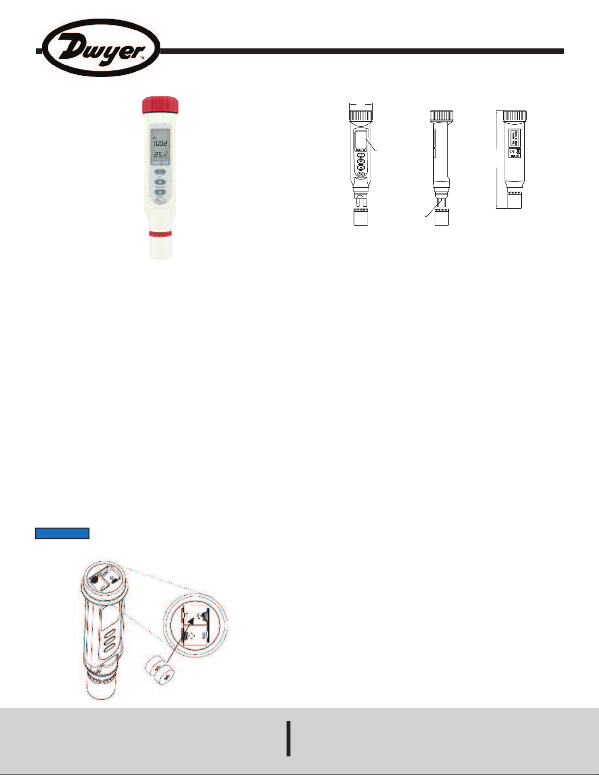
Waterproof Cond./TDS Testing Pen
Specifications - Installation and Operating Instructions
he Model TDS2-10 Cond./TDS Testing Pen monitors both conductivity and total
T
issolved solids in streams, rivers, or any other body of water. It picks up impurities
d
and dissolved solids while checking the conductivity at the same time. This pocket
sized tester is constructed of a durable ABS plastic waterproof housing and 316
SS electrodes to protect against corrosion. A large LCD display is easy to read and
shows both the conductivity/total dissolved solids and temperature measurements
imultaneously. Since change in temperature can affect accuracy, the TDS2-10
s
as automatic temperature compensation. Batteries (four LR44 alkaline) included
h
in packaging.
OPERATING INSTRUCTIONS
Introduction
Please read the manual completely before using this meter. Filing and keeping the
manual for future reference is recommended. It is also recommended to soak the
electrode for at least 30 minutes before using the meter to clear anything affecting
the probe.
Power Supply
The meter is powered by 4 LR44 button cell batteries. Check the batteries if it is
your first time use, if the battery symbol appears on the LCD, or if the meter cannot
power on.
To install the batteries:
1. Turn off the meter.
2. Loosen the battery cover in the counterclockwise direction (DON’T discard the
black washer!).
3. Replace the old batteries with four new button cell LR44 batteries.
4. Make sure the batteries are in place and the polarity is correct.
5. Put the battery cover back and turn it tightly in the clockwise direction.
NOTICE
instrument.
Remove the batteries from instruments that you do not plan to
use for a month or more. Do not leave batteries in the
SPECIFICATIONS
Wetted Materials: ABS plastic and 316 SS.
ange:
R
onductivity: 0 to 1999 uS or 0 to 19.99 mS;
C
DS: 0 to 1999 ppm or 0 to 19.99 ppt.
T
Accuracy: ±1% FS.
Display: 30 mm H x 18 mm W LCD dual display.
Resolution:
Conductivity: 1uS or .01 mS;
TDS: 1 ppm or .01 ppt.
Temperature Limits: 32 to 122°F (0 to 50°C).
Power Requirements: (4) 1.5 V LR44 alkaline batteries, installed functional, user
replaceable.
Enclosure Material: ABS.
Enclosure Rating: IP65.
Weight: 4.3 oz (115 g).
Agency Approval: CE.
DWYER INSTRUMENTS, INC.
Phone: 219/879-8000 www.dwyer-inst.com
P.O. BOX 373 • MICHIGAN CITY, INDIANA 46360, U.S.A. Fax: 219/872-9057 e-mail: info@dwyer-inst.com
Page 2
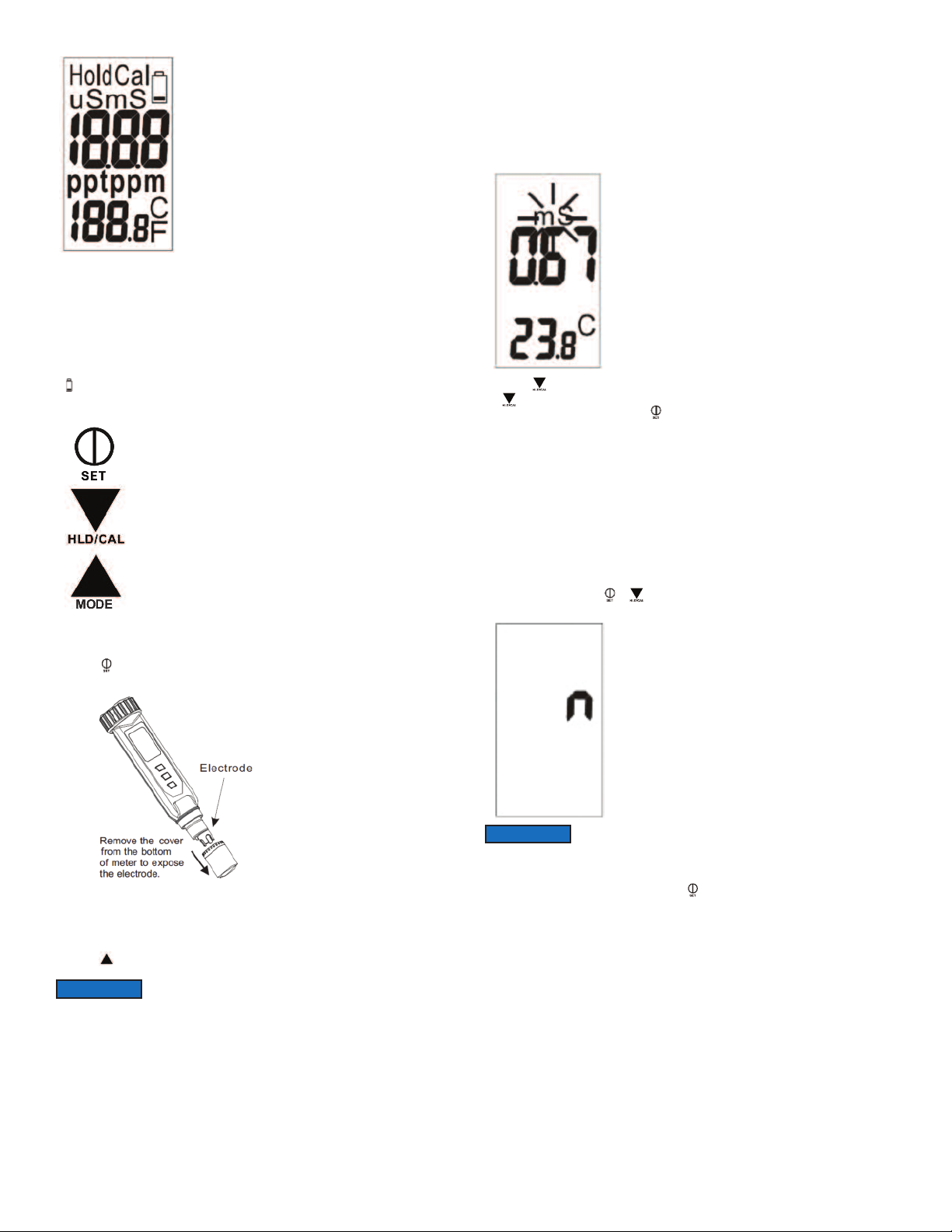
LCD Display
- The top shows the measured reading.
The bottom shows the reading of the temperature.
-
Cal = Calibration mode.
-
Hold = Data hold.
-
- Microseconds (uS) or milliseconds (mS) is the unit of Conductivity.
- Parts per thousand (ppt) or parts per million (ppm) is the unit of TDS.
- C or F is the unit of the liquid temperature.
- is the battery low icon.
eypad
K
7. Dip the probe into the sample. Make sure there are no air bubbles trapped in the
slot of the probe. To remove air bubbles, give the probe a gentle stir. Make sure the
electrode tip is submerged when you stir it.
. Stir the probe gently in the sample to create a homogeneous sample. Allow a few
8
econds for it to reach temperature equilibrium (wait about 15 minutes to get a
s
table reading).
s
. The unit of measurement will flash on the LCD to indicate that the meter is in
9
measurement mode. When the reading is stable, the unit will stop flashing.
10. Press to freeze current readings. The text “Hold” will appear on the LCD. Press
gain to release.
a
1. Turn off the meter by pressing .
1
2. Make sure your electrode is clean and store it carefully. Before storage, rinse it
1
carefully in de-ionized water and store dry with the cap. Remember the storage
temperature limits. For more information, see the maintenance section.
13. Air bubbles can easily adhere around the gap between the electrode and the
meter; this will affect the accuracy. See the troubleshooting section for more
etails on how to remove air bubbles.
d
Operation
1. Remove the probe cover from the meter to expose the electrode.
2. Press to power on the meter. The LCD will display parameters (ex: tnr, tCo, tds,
rAn) in turns and then it will enter normal display.
3. The meter is default in auto-ranging status once powered on. Auto-ranging
determines and selects a range which gives you the greatest resolution and
accuracy. Alternatively, you can manually select the ranges. For example, if
you prefer the meter to display a reading such as .50 mS instead of 500 uS, you
press for more than 2 seconds.
uto Power off (Sleep Function)
A
This meter will shut off automatically after 20 minutes of inactivity. For a longer
operating time, you can disable sleep mode.
To disable the auto power off:
Before power on, press + simultaneously until an “n” appears on the screen.
Then, release the keys to return to normal mode.
NOTICE
Setup
The advanced setup mode lets you customize your meter’s preferences and defaults.
To change the parameters, you can press for more than 2 seconds. You will enter
setup mode when the meter is in measurement mode.
The disable sleep mode will be invalid after every power off.
NOTICE
- The LCD will display E02/E03 if the measured value is below or over the limit
value, please re-select the range.
4. Set the temperature coefficient to the correct value. The meter is factory set to
2.1%/°C. This will normally provide good results. See the setup section to set the
temperature coefficient if needed.
5. Select the normalization temperature. The meter is factory set to 77°F (25°C). If you
need to normalize the meter to 68°F (20°C), see the set up section for details.
6. Rinse the probe with de-ionized or distilled water before use. This will remove any
impurities adhering to the electrode. If the meter is not used for a long time, please
soak the probe for more than 30 minutes to clear up the lazy effect of the probe.
- Accuracy is a percent of the full-scale, so using your meter in
the lowest range will result in the greatest accuracy.
Page 3
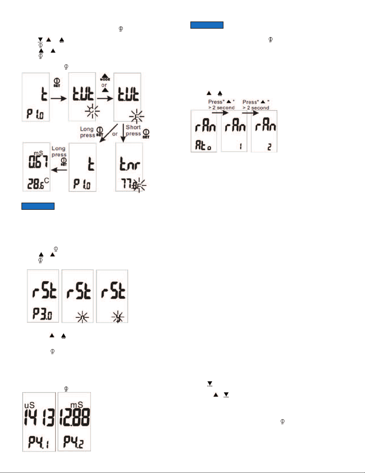
1.0 Temperature Parameter Setting (t)
P
. When the meter is in measurement mode, press f for more than 2 seconds to
1
nter setup mode.
e
. Press , , or to select P1.0.
2
3. Press momentarily again to enter unit setting.
4. Press or to select C or F.
5. Press momentarily to confirm the unit, or press it for more than 2 seconds to
eturn to P1.0 without saving.
r
. While in P1.0, press for more than 2 seconds to return to measurement mode.
6
NOTICE
n P1.0, P2.0, P3.0, P4.0, you can press for more than 2 seconds to return to
I
normal measurement mode.
Select Measure Range (rAn)
wo measurement ranges are available for each parameter. For conductivity, users
T
an select either 0 to 1999 uS or 0 to 19.99 mS. For TDS, users can select either
c
to 1999 ppm or 0 to 19.99 ppt.
0
pt = parts per thousand
p
To manually select the measurement range:
1. Turn off the meter and stay in normal measurement mode.
2. Press or for more than 2 seconds to select the range.
(Default)
Calibration Mode (CAL)
reparing for Calibration
P
wo issues need to be considered and prepared for before operation. First, what
T
s the right calibration standard? Second, when should you calibrate?
i
What is the right calibration standard?
4.1 & P4.2 are only for you to “review” the calibration
P
information, not for calibration.
NOTICE
P3.0 Reset Meter (rSt)
When you decide to reset the meter, all parameters will be reset to factory default
values, including the calibration information.
P3.1 Reset
1. In P3.0, press momentarily to enter P3.1.
2. Press or to select Y or N.
3. Press momentarily to confirm the state and return to P3.0, or press it for more
than 2 seconds to return to P3.0 without confirming the P3.1 value.
P4.0 Review Calibration Information (CAL)
In P3.0, press or to select P4.0.
P4.1 Range 1 Calibration Information
In P4.0, press momentarily to enter P4.1 and you will see the last calibration
concentration. If the meter is not yet calibrated, “---”will display on the LCD.
P4.2 Range 2 Calibration Information
In P4.1, press or to enter P4.2 and you will see the last calibration concentration.
If range 2 is not yet calibrated, “---” will display on the LCD.
In P4.1 or P4.2, press momentarily to confirm the state and return to P4.0.
The text P1.1, P1.2, P1.3, P2.1, P3.1 will not display on the
LCD.
For best results, select a conductivity or TDS standard near the sample value that
you are measuring. Alternatively, conductivity or TDS use a calibration solution
value which is approximately 2/3 of the full- scale range you plan to use.
DO NOT reuse the calibration solution. Contaminants in the solution will affect the
calibration and the accuracy. Be sure to use fresh solution each time.
When should you do a calibration?
Calibration is necessary and should be done regularly.
If you are measuring the mid-ranges, calibrate the meter at least once a month.
Soak the probe for 15 minutes before calibration or measurement. This can
saturate the probe surface and minimize drift. If measured at the extreme
temperatures or in a concentration of conductivity 100 mS or TDS 2 mS or <100
ppm or >2 ppm. Calibrate the meter at least once a week to get specified accuracy.
Conductivity and TDS Calibration
Please follow the below steps for the conductivity or TDS meter calibration:
1. Insert the probe into de-mineralized or distilled water for about 30 minutes to
rinse the probe.
2. Select the conductivity or TDS standard which is close to your measurement
range. The factory default setting of the TDS conversion factor is 0.50. If your
solution has a different TDS factor, you can improve the calibration accuracy by
setting the TDS factor before starting the calibration. To convert the TDS factors
to the correct value, please refer to the value provided by standard solution
manufacturer.
3. Pour 3 cm height of the standard into two separate and clean containers.
4. Turn on the meter. Press the mode button to switch between TDS and
conductivity.
5. Rinse the probe in one of the containers. Gently stir the probe. Rinsing could
remove contaminants that affect the calibration and could prevent error.
6. Dip the rinsed probe into the other container. Tap the probe at the bottom of the
container to remove air bubbles. Let the probe stabilize to the solution
temperature.
7. Press for more than 2 seconds to begin the calibration. The conductivity and
TDS value will blink on the LCD.
8. Press the or to adjust the value to match the value to the calibration
standard. You can adjust the conductivity or TDS reading up to ±30% from the
detected value. If the detected value and standard values differ by more than
±30%, it means that the electrode needs to be cleaned. The meter is defaulted
at 25°C.
9. When the “CAL” stops blinking, you can press to confirm the value. The meter
will switch back to conductivity and TDS measurement mode. If “CAL” always
blinks, check the solution and make sure it is stable. Make the input in step 8
equal to the solution value.
10. Repeat steps 1 through 9 for other ranges if needed.
Page 4

ption 2: Using Conversion Factors
O
DS values are related to conductivity. You can calibrate the meter by using
T
onductivity standards as described above and then program the meter with a
c
iven conversion factor. Please refer to below steps.
g
1. Perform the conductivity calibration procedure.
2. Select the correct conductivity-to-TDS conversion factor for other solutions using
the formula: Factor = Actual TDS = Actual Conductivity @ 25°C.
. When the meter is in measurement mode, press “set button” for more than 2
3
econds. Press “up” to get to P2.0. In P2.0 press “set button picture”
s
omentarily to enter P2.1. The factor will flash on the LCD. Press “up” or “down”
m
o change factor from 0.40 to 1.00. Press “set button picture” momentarily to
t
confirm the value and the meter will return to P2.0.
NOTICE
range limit or 10% of the range limit.
hen switching the meter from measurement to calibration mode, the meter will
W
isplay the factory default value. If the meter was previously calibrated, the display
d
may seem to jump to the factory default value when entering calibration.
Symptom
ower on but no display
P
isplay disappeared
D
ir bubbles adhere on
A
electrode
If the standard buffer is over the measuring limit or less than
10% of the measuring limit, the displayed value will equal the
Action
. Make sure the time of pressing the power key is
1
ore than .3 seconds.
m
. Check that the batteries are in place and make good
2
contact, minding polarities.
3. Replace new batteries.
4. Move the battery away for one minute and then put
back in.
heck whether the low battery icon was on before the
C
isplay went off. If yes, replace with new batteries.
d
. Stir the electrode completely and dip it into the
1
solution at an oblique angle. Dipping the electrode in
vertically creates many air bubbles.
2. After soaking the electrode in solution for 15 to 30
minutes, inspect the electrode carefully to make sure
no air bubbles adhere. If they still exist, tap the bottom
of the container gently and stir the electrode to remove
the air bubbles.
3. If the above method is not working, remove the
electrode out of the solution and blow at the electrode
to remove the air bubbles.
Error Code Meaning
Parameter: Conductivity
eter is in manual ranging 1;
---
03
E
E04
arameter: TDS
P
--
-
E04
Parameter: Temperature
01
E
E02
E03
Appendix: Meter Factory Default Setting
Type
P1.1
P1.2
P1.3
P2.1
P3.1
P4.1
P4.2
M
owever, the conductivity
h
easured value is higher than
m
999uS.
1
Conductivity value is over the
range limit (19.99mS) or meter is
damaged.
he original temp. error results in
T
his error.
t
eter is in manual ranging 1;
M
owever, the TDS measured
h
value is higher than 1999*TDS
factor ppm.
The original temp. or
onductivity error results in this
c
rror.
e
emperature circuit is damaged.
T
emperature value is lower than
T
range limit (0°C) or temperature
circuit is damaged.
emperature value is higher
T
than range limit (50°C) or
temperature circuit is damaged.
Parameters
Select °C/°F
Nor. Temp.
Temp. Coefficient
TDS Factor
Factory Default
Viewing Previous
Calibration Data
Default
°C
25°C
2.1%/°C
0.50
NO
---
---
Remark
Temperature Unit
Selectable: 25 or 20°C
Adjustable from 0.4 to 10%
Adjustable from 0.40 to 1.00
(only for 8361)
Retain Your Current Settings
No Calibration Data for 1st
Range
No Calibration Data for 2nd
Range
ow to Handle?
H
ress “UP” key more than 2
P
econds to change the mode to
s
anual ranging 2 or auto
m
anging.
r
Put the meter in standard buffer
(the buffer concentration must be
lower than range limit). If E03 still
ppears, send back for repair.
a
efer to below error code of
R
emp. After solving the error of
t
emp, E04 of conductivity will
t
disappear.
ress “UP” key more than 2
P
econds to change the mode to
s
manual ranging 2 or auto
ranging.
Refer to below error code of
emp. & conductivity. After
t
olving the error of temp, &
s
onductivity, E04 of TDS will
c
disappear.
Send back for repair.
Put the meter in room
temperature for 5 minutes to
make the readying back to
ormal. If E02 still appears,
n
end back for repair.
s
ut the meter in room
P
temperature for 5 minutes. If
E02 still appears, send back for
repair.
MAINTENANCE/REPAIR
Upon final installation of the Series TDS2-10, no routine maintenance is required.
The Series TDS2-10 is not field serviceable and should be returned if repair is
needed. Field repair should not be attempted and may void warranty.
WARRANTY/RETURN
Refer to “Terms and Conditions of Sales” in our catalog and on our website. Contact
customer service to receive a Return Goods Authorization number before shipping
the product back for repair. Be sure to include a brief description of the problem
plus any additional application notes.
©Copyright 2013 Dwyer Instruments, Inc. Printed in U.S.A. 6/13 FR# R6-444017-00 Rev. 2
DWYER INSTRUMENTS, INC.
Phone: 219/879-8000 www.dwyer-inst.com
P.O. BOX 373 • MICHIGAN CITY, INDIANA 46360, U.S.A. Fax: 219/872-9057 e-mail: info@dwyer-inst.com
 Loading...