

Page 1
F-SPK
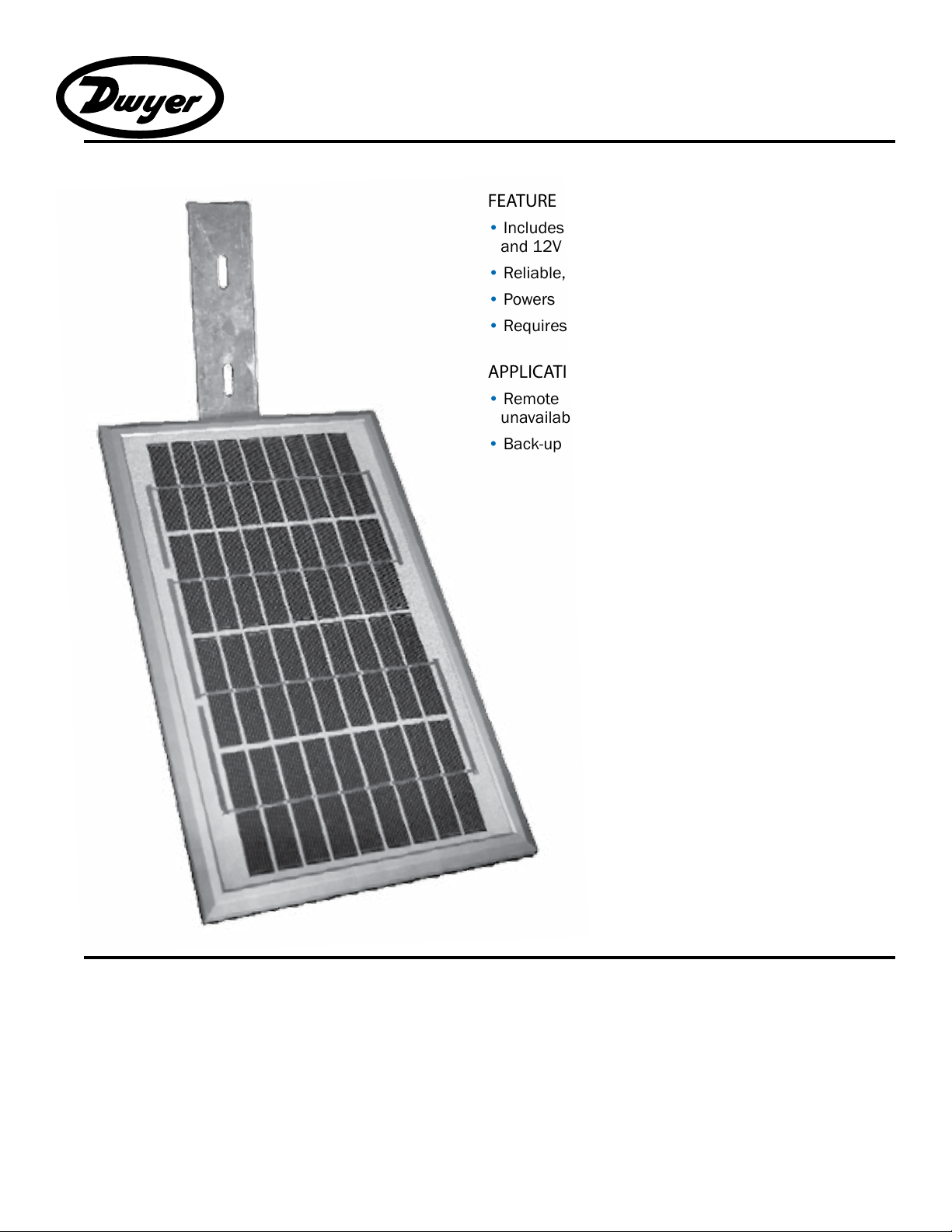
SPK
TM
Solar Panel
FEATURES
• Includes 5 watt solar panel, mounting hardware,
and 12V solar charge controller
• Reliable, maintenance-free operation
• Powers Dwyer Instruments Inc. ow meters
• Requires a 22-33 Amp-hour Sealed Lead Acid battery
APPLICATIONS
• Remote metering applications where electricity is
unavailable
• Back-up power supply for uninterrupted operation
GENERAL INFORMATION
The SPK solar panel makes it possible to use Dwyer Instru-
ments Inc. owmeters in remote applications where a reliable
source of electricity is not available or practical. The SPK is
intended for use with a standard 12V, 22-33 Amp-hour Sealed
Lead Acid battery (not included). It comes standard with a
charge controller and corrossion-resistant mounting hardware.
The SPK can also be used to provide up to a 40-day back-up
power supply for periods of darkness.
Page 2

SPECIFICATIONS*
SPK
TM
Solar Panel
Electrical Current
Voltage
Dimensions Height
Width
Weight
Mounting
Operating Temperature Range
Change Controller
*Specications subject to change
290 mA (typical at design operating point)
17 V (typical at design operating point)
14.2”
8.5”
4 pounds (solar panel and mounting bracket)
Bracket, band clamps and mounting hardware for 1-1/2 or 2 inch vertical pipe
-40˚ F to +158˚ F (-40˚ C to +70˚ C)
High efciency series PWM regulator with temperature compensation and built-in lightning protection
BATTERY SELECTION
For powering Dwyer Instruments Inc. mechanical meters
along with display electronics, use a 12V Sealed Lead Acid
(SLA) deep-cycle battery with a minimum capacity of 22 Amphours. This should provide a conservative 40 day backup with
maximum battery service life. Marine/RV grade deep-cycle
batteries or automotive batteries may be used but must be
upsized in Amp-hour capacity by two times and four times
respectively to achieve the same battery service life in most
applications.
For powering Dwyer Instruments Inc. low power (<50mA)
magnetic ow meters use only deep-cycle SLA batteries (not
marine/RV orautomotive grade batteries) with a minimum ca-
pacity of 33 Amp-hours. In climates where meters are operating in full pipe mode much of the time with extended periods
of cloudy days, operating continuously through the year, or in
latitudes above 50 degrees, the required battery Amp-hour
capacity should be reviewed before selection. To learn more,
consult the Appendix in our solar power application note
found at www.dwyer-inst.com.
In summary, the minimum recommended battery capacity, as
described above, will be adequate in most climates and applications. However, under marginal conditions, a larger capacity battery may provide superior reliability, better battery
service life and lower life-cycle costs.
LOCATION
The solar panel should oriented as much as possible toward
the midday sun. Locate where there is no signicant shading
of the solar panel. The Solar Charge Controller and Sealed
Lead Acid (SLA) battery should be located in close physical
and thermal proximity. Both must be shaded from direct
sunlight to minimize temperature differences between them
which will greatly diminish the battery service life. Also insulate
the bottom of the battery if heat could be absorbed from the
surface (concrete, metal etc.) on which the battery is resting.
Also take measures to prevent accumulation of moisture (rain,
snow, ice, ooding) between the battery terminals which could
discharge the battery.
If the battery and Solar Charge Controller are housed in an
enclosure, the outside must be white or shiny metallic to minimize solar heat build up inside that is seriously detrimental
to the service life of the battery. Even light colors (such as the
standard ANSI 61 Gray) can elevate the interior of the enclosure
by 40F (22C.) If other colors are used, the enclosure must be
shaded from direct sunlight or painted glossy white. In addition,
because even sealed batteries could vent if the Solar Charge
Controller fails, for safety reasons the enclosure should be
vented, particularly if it contains other electrical equipment.
Page 3

INSTALLATION
SPK
TM
Solar Panel
The solar panel is designed to mount to a either a 1-1/2 to 2
inch diameter vertical pipe. First attach the 45 degree angle
bracket to the panel with the two M6 bolts, at washers and
nuts provided as shown. Before tightening the bolts. Be sure to
position the bracket to the side of the black cable cover rather
than over it to avoid stressing the panel. (At latitudes above 50
degrees performance may be improved by bending the bracket
so that the angle of the panel to the horizontal is increased
to approximately the local latitude plus 15 degrees. To avoid
damage to the panel, do this before bolting the bracket to the
panel). Next use the two sets of ¼-20 bolts, nuts, at and
lock washers to attach the angle bracket to the pipe mount
C-channel. Then attach the entire assembly to the pipe using
the two band clamps as shown. Turn the panel to face true (not
magnetic) south in the northern hemisphere or north in the
southern hemisphere before tightening the clamps securely.
Connect the solar charge controller, ow meter and battery
as shown in the wiring diagram. Clean battery terminals and
secure connections to the battery using grease or other means
of preventing corrosion. For safety, an in-line fuse holder should
be installed at the positive battery connection with a 1 Amp
time lag (slow-blow) fuse. In unprotected locations a weatherproof fuse holder (such as Bussmann HFB-R) and outdoor-rated
wirenuts should be used.
1-1/2 to 2 inch pipe
1/4-20 hardware
solar panel
M6 hardware
C-channel
band clamps
Page 4

WIRING DIAGRAM
TM
SPK
Solar Panel
MAINTENANCE
Periodic cleaning of the solar panel glass is recommended to
remove dust accumulation. Snow and ice may need removal if it remains more than 2 weeks. Installing the panel at a
steeper than 45 degree angle may make this unnecessary in
most areas. Battery service life for good quality SLA batteries
should be 4-6 years. Actual maintenance replacement interval will depend on local conditions and criticality of data.
WARRANTY/RETURN
Refer to "Terms and Conditions of Sale" in our catalog or on our website. Contact customer service to receive
a Returns Goods Authorization number before shipping
your product back for repair. Be sure to include a brief
description of the problem plus any relevant applciation
notes.
TM
Dwyer Instruments, Inc. • 102 Indiana Highway 212 • Michigan City, IN 46360 • USA
(P) 219.879.8868 • (F) 219.872.9057 • 1.800.872.9141 • www.dwyer-inst.com
PL-OM-65200394-082012
8/20/12
 Loading...