

Page 1
Instruction Manual for DIN Rail mounting type indicating
controller SCZ10
Version 1.0 - Feb,2003
To prevent accidents arising from the misuse of this controller, please ensure the operator using it
receives this manual.
Caution
• This instrument should be used according to the specifications described in this manual.
If it is not used according to the specifications, it may malfunction or breakdown.
• Be sure to follow the warnings, cautions and notices. If not, serious injury or accidents may occur.
• The specifications of the SCZ10 and the contents of this instruction manual are subject to change
without notice.
• Care has been taken to assure that the contents of this instruction manual are correct, but if there are
any doubts, mistakes or questions, please inform our sales department.
• Be sure to check that the power is turned off when cleaning this instrument.
• Use a soft and dry cloth when cleaning the instrument.
(If paint thinner is used, it might deform or tarnish the unit.)
• As the display section is vulnerable, do not strike or scratch it with a hard object.
Any unauthorized transfer or copying of this document, in part or in whole, is prohibited.
•
• Love Controls is not liable for any damages or secondary damages incurred as a result of
using this product, including any indirect damages.
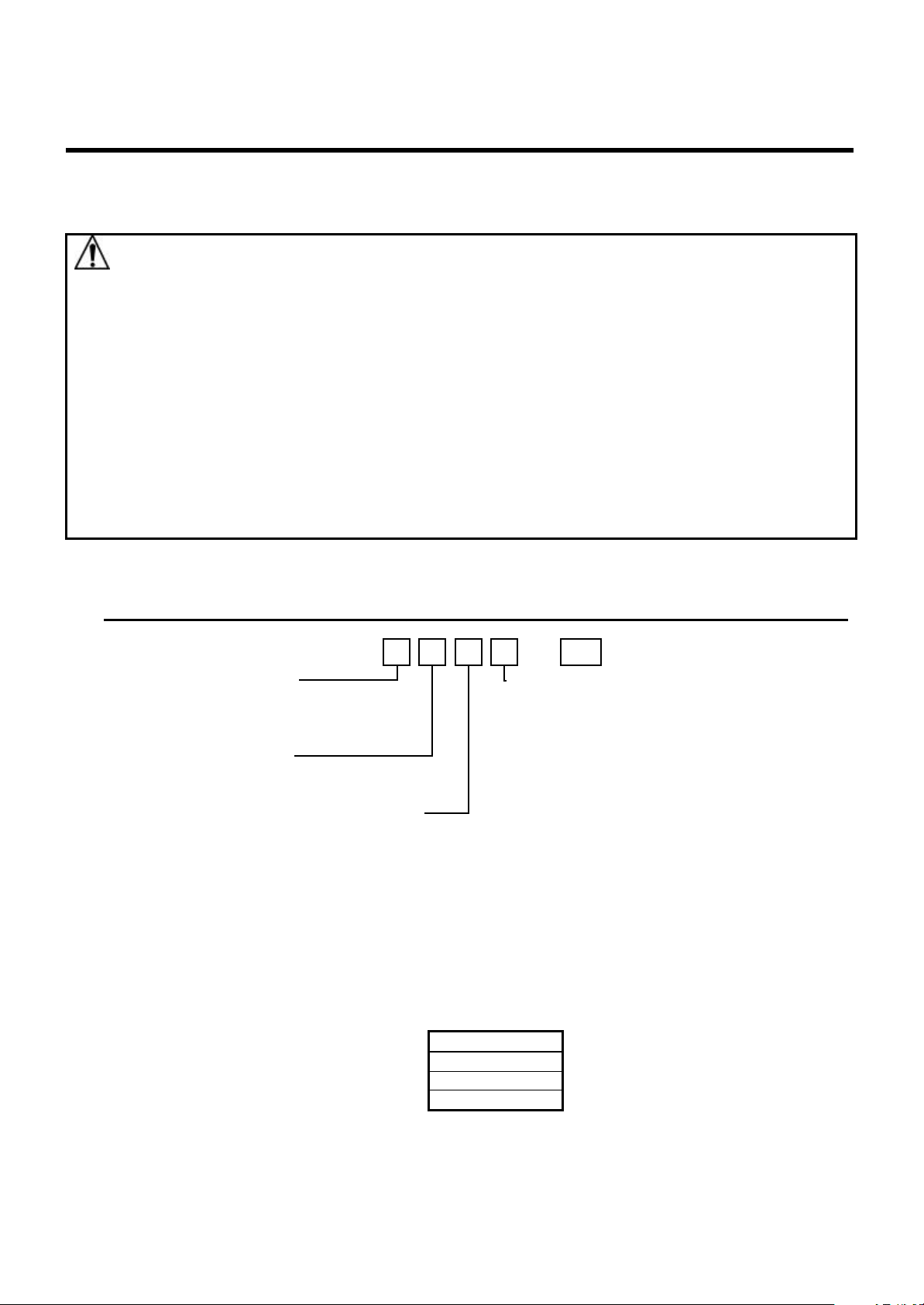
1. Model Identification
1.1 Model name
SCZ10——***
Output
1 = Relay
2 = Switched Voltage
3 = Current (4~20mA)
Power
0 = Line (120~240 VAC/VDC)
1 = Low (24VAC/VDC
RS-485 Communications*
0=No
1 = Modbus® RTU
Notes:
* The RS-485 and Heater Burnout Alarm options are mutually exclusive.
** The Current Alarm is only available for outputs 1 and 2.
1.2 Model name label
Model name label is on the right side of the case and the bottom of the inner assembly.
In the case of Heater burnout alarm output, CT rated current value is written in the bracket ( ).
Heater Burnout Alarm**
0=No
1=Yes
*** Max. Current
00=NA
05=5Amps
10 = 10 Amps
20 = 20 Amps
50 = Amps
Model name ---------------------------------Option -----------------------------------------Option -----------------------------------------Instrument No. (Inner assembly only)--
SCZ10-1001-05
No. XXXXXX
Relay contact output/ Multi-range input
Heater burnout alarm output
Page 2
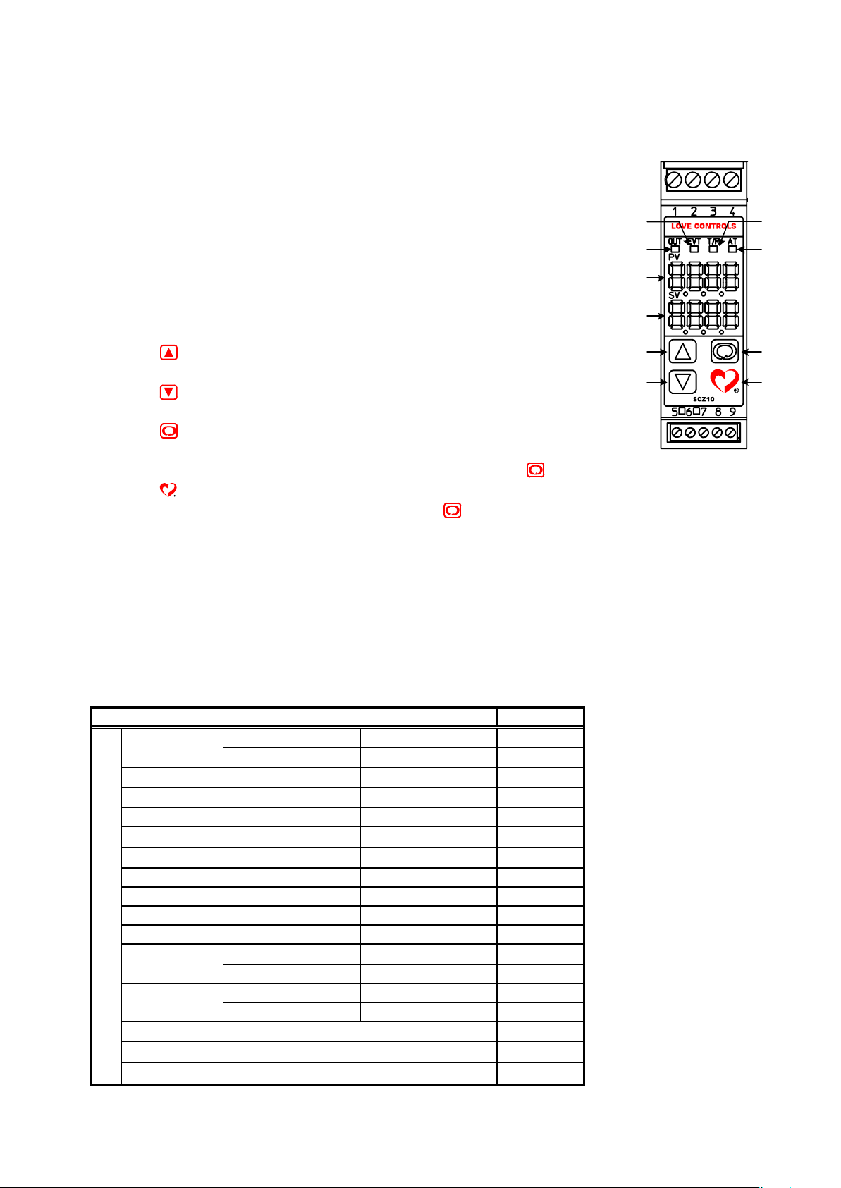
2. Name and functions of the sections
(1) Event (EVT) output action indicator
A red LED lights when Event output [Alarm, Loop break alarm or Heater burnout alarm (Option)]
is ON.
(2) Control output (OUT) action indicator
A green LED lights when the control output (OUT) is ON.
(3) Serial communication output indicator
A yellow LED blinks while serial communication TX (sending) is output.
(4) PID auto-tuning action indicator
A yellow LED blinks while PID auto-tuning is functioning.
(5) PV display
Indicates actual temperature (PV) with a Red LED.
(6) SV display
Indicates setting value (SV) with a Green LED.
(7) key
Increases numeric value on the SV display or switches the selected item.
(8) key
Decreases numeric value on the SV display or switches the selected item.
(9) key
Changes the Menu Item or enters the value for the selected Menu Item.
(Enters the setting value for that Menu Item by pressing the key. Fig.2-1
(10) key
Allows entry into Setup Menu when used with the
key.
(1)
(2)
(5)
(6)
(7)
(8)
(3)
(4)
(9)
(10)
3. Operation
The sensor input character and temperature unit are indicated on the PV display for approx. 3
seconds after the power is turned on, and the rated scale maximum value is indicated on the
SV display. (Table 3.1-1)
(If the other value is set in the scaling high limit value, it is indicated on the SV display.)
During this time all outputs and the LED indicators are on their OFF status. After a while
control starts indicating actual temperature on the PV display and setting value on the SV display.
(Table 3.1-1)
Input Scale range Resolution
M
C(W/Re5-26) 0 to 2315°C 0 to 4200°F 1 °C (°F)
4 to 20mA -1999 to 9999 *1, *2 1
0 to 20mA -1999 to 9999 *1, *2 1
K
J 0 to 1000°C 0 to 1800°F 1 °C (°F)
R 0 to 1760°C 0 to 3200°F 1 °C (°F)
S 0 to 1760°C 0 to 3200°F 1°C (°F)
B 0 to 1820°C 0 to 3300°F 1°C (°F)
E 0 to 800°C 0 to 1500°F 1 °C (°F)
T -199.9 to 400.0°C -199.9 to 750.0°F 0.1°C (°F)
N 0 to 1300°C 0 to 2300°F 1 °C (°F)
PL-II 0 to 1390°C 0 to 2500°F 1 °C (°F)
Pt100
JPt100
0to1V
0 to 1370°C 0 to 2500°F 1 °C (°F)
0.0 to 400.0°C 0.0 to 750.0°F 0.1°C (°F)
-199.9 to 850.0°C -199.9 to 999.9°F 0.1°C (°F)
-200 to 850°C -300 to 1500°F 1 °C (°F)
-199.9 to 500.0°C -199.9 to 900.0°F 0.1°C (°F)
-200 to 500°C -300 to 900°F 1 °C (°F)
-1999 to 9999 *1 1
*1: Scale range and
decimal point place
can be selected
*2: Connect 50Ω shunt
resistor (sold separately)
between input terminals.
Page 3
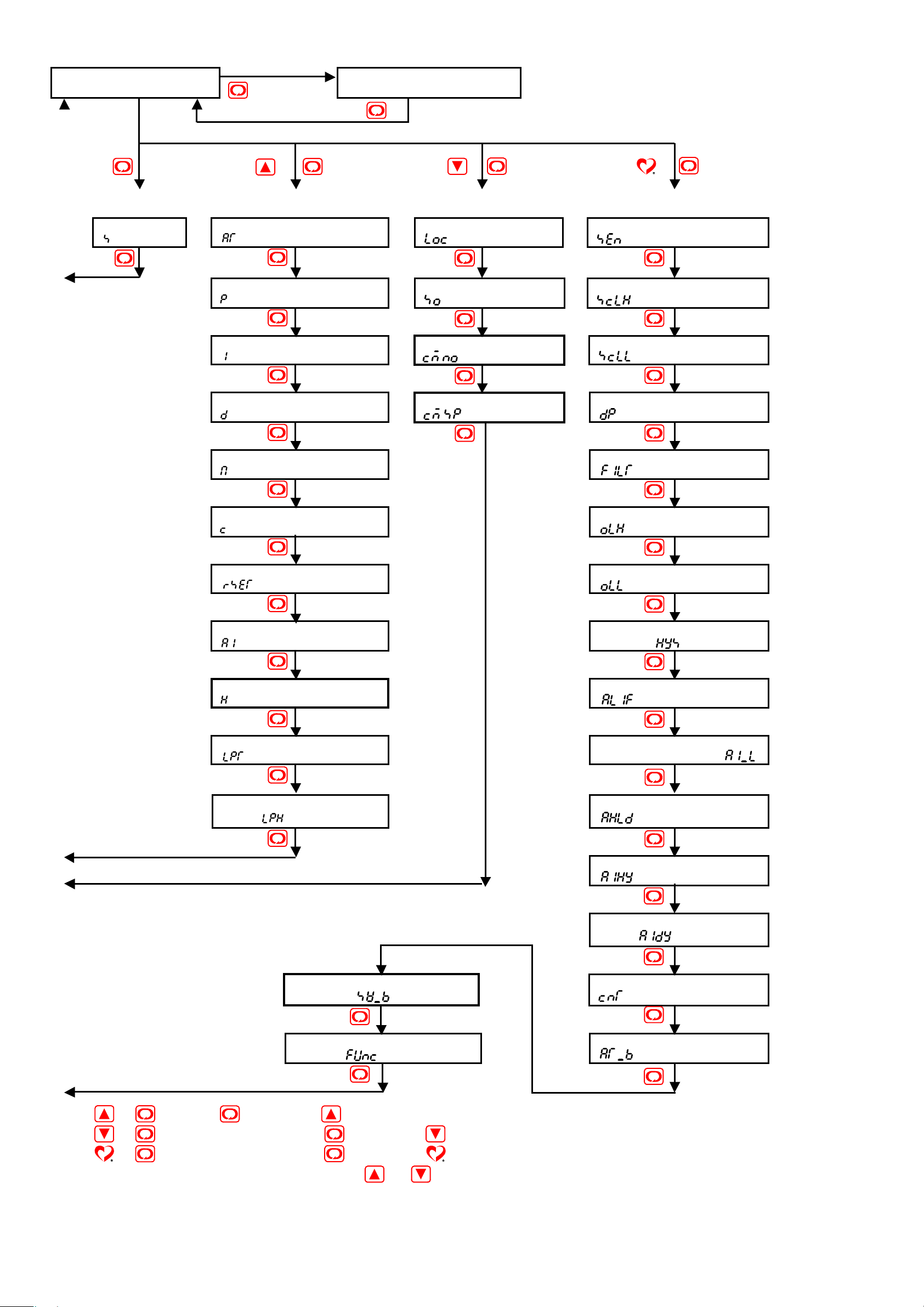
3.1 Operation flow chart
PV/SV display mode
[Main Menu] [Secondary Menu]
mode 2
Main setting
[]
]
PID auto-tuning Perform/Cancel
[]
Proportional band setting
[]
Integral time setting
[]
Derivative time setting
[]
(Approx. 3s)
+ + (Approx. 3s) + (Approx. 3s)
Control output MV indication
[Auxiliary Menu] [Secure Menu]
Setting value lock selection
[]
Sensor correction setting
[]
Instrument No. setting
[]
Data transfer rate selection
[]
Sensor selection
[]
Scaling high limit setting
[]
Scaling low limit setting
[]
Decimal point place selection
[]
Anti-reset windup setting
[]
Proportional cycle setting
[]
Manual reset setting
[]
Alarm setting
[]
Heater burnout alarm setting
[]
Loop break alarm time setting
[]
PV filter time constant setting
[]
Control output high limit setting
[]
Control output low limit setting
[]
Control output ON/OFF action
hysteresis [ ]
Alarm action selection
[]
Alarm action
Energized/Deenergized [ ]
Loop break alarm action span
setting [ ]
Setting value digital transmission
bias setting [ ]
Controller/Converter function
selection [ ]
• + : Press the key while the key is being pressed.
Alarm HOLD function selection
[]
Alarm hysteresis setting
[]
Alarm action delayed timer
setting [ ]
Direct/Reverse action selection
[]
AT bias setting
[]
• + (Approx. 3 seconds): Press the key while the key is being pressed.
• + (Approx. 3 seconds): Press the key while the key is being pressed.
For setting and selecting in each setting mode, press or key.
Page 4
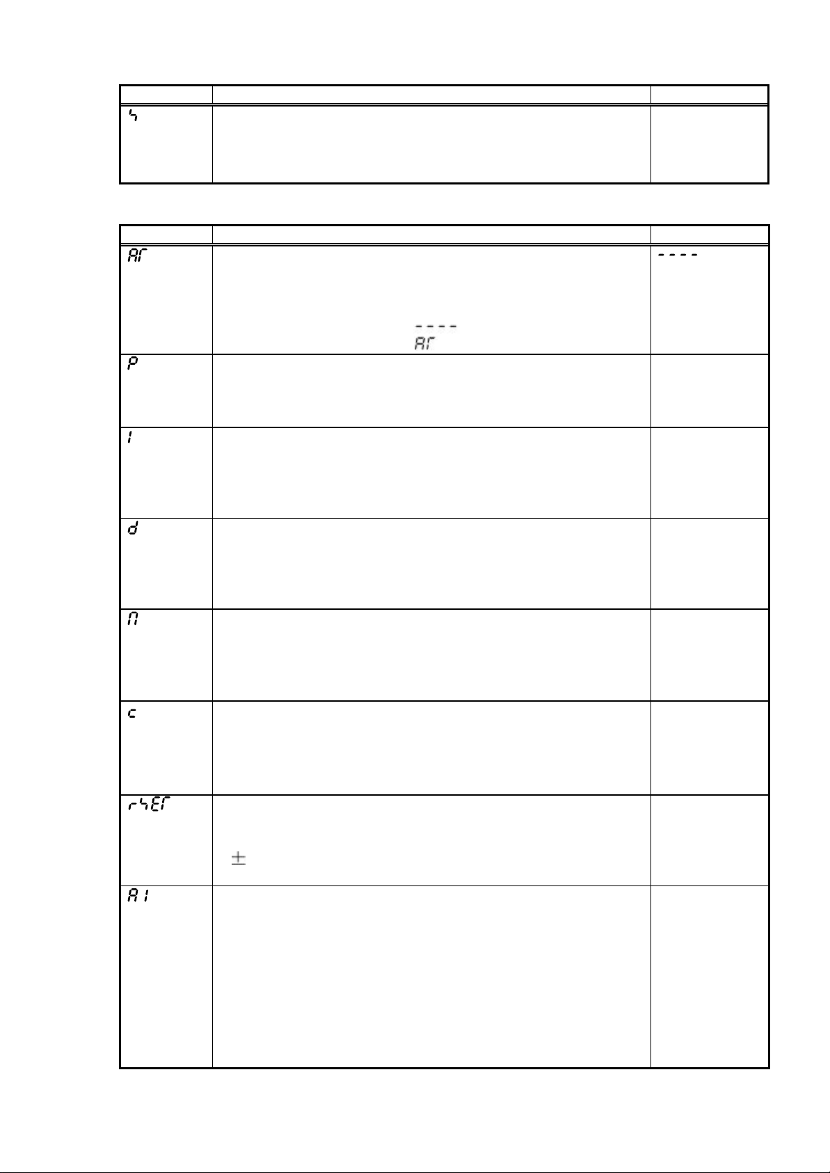
3.2 Main setting mode
Character Name, Description, Setting range Initial value
Main setting
• Set the value for controlled objects.
Scaling low limit setting value to Scaling high limit setting value
•
(Decimal point place follows the selection for DC current input)
3.3 Sub setting mode
Character Name, Description, Setting range Initial value
PID auto-tuning Perform/Cancel
• Performs PID auto-tuning. However when PID auto-tuning does
not finish after 4 hours it started, PID auto-tuning is shut down
compulsory.
• PID cancellation :
PID auto-tuning performing:
Proportional band setting
• Sets the proportional band.
• ON/OFF action when setting the value to 0.0
• 0.0to110.0%
Integral time setting
• Sets the integral time.
• Setting the value to 0 disables this function.
• This setting item is not indicated for ON/OFF action.
• 0to1000seconds
Derivative time setting
• Sets the derivative time.
•
Setting the value to 0 disables this function.
• This setting item is not indicated for ON/OFF action.
• 0 to 300 seconds
Anti-reset windup setting
• Sets anti-reset windup.
• Setting the value to 0 disables this function.
• This setting item is indicated only for PID action.
• 0to100%
Proportional cycle setting
• Sets the proportional cycle value for the control output (OUT).
• This setting item is not indicated for ON/OFF action or DC
current output.
• 1 to 120 seconds
Manual reset setting
• Sets the resetting value manually.
• This
• Proportional band converted value (In the case of DC voltage
and current input, decimal point place follows the selection.)
Alarm setting
• Sets the action point for the alarm output.
•
Setting the value to 0 or 0.0 disables this function.
(excluding Process high and Process low alarm)
When Loop break alarm and Heater burnout alarm are applied
together, the output is common.
• This setting item is not indicated when “No alarm” action is
selected in [Alarm action selection].
• See (Table 3.3-1). (In the case of DC voltage and DC current
input, decimal point place follows the selection.)
0° C
2.5%
200 seconds
50 seconds
50%
Relay: 30 Sec.
Solid State: 3 Sec.
0.0
setting item is indicated only for P and PD action.
0° C
Page 5
Character Name, Description, Setting range Initial value
Heater burnout alarm setting
0.0A
• Sets the heater current value for Heater burnout alarm.
• Setting the value to 0.0 disables this function.
• Self-holding is not available for the alarm output.
When
the output is common.
alarm and Loop break alarm are applied together,
• This setting item is not indicated when [Option: W] is not added.
• Rating 5A : 0.0 to 5.0A Rating 20A: 0.0 to 20.0A
Rating 10A: 0.0 to10.0A Rating 50A: 0.0 to 50.0A
Loop break alarm time setting
0 minutes
• Sets the time to assess the Loop break alarm.
• Setting the value to
0 disables this function.
• When alarm and Heater burnout alarm are applied together,
the output is common.
• 0 to 200 minutes
Loop break alarm action span setting
0°
• Sets the action span to assess the Loop break alarm.
• Setting the value to
0 disables this function.
• When alarm and Heater burnout alarm are applied together,
the output is common.
•Thermocouple and RTD input
0to150
DC voltage and DC current input
0 to 1500 (Decimal point place follows the selection)
( ) or 0.0 to 150.0 ( )
(Table 3.3-1)
Alarm action type Setting range
High limit alarm -(Scaling span) to Scaling span
Low limit alarm -(Scaling span) to Scaling span
High/Low limits alarm 0 to Scaling span
High/Low limit range alarm 0 to Scaling span
Process high alarm Scaling low limit setting value to high limit value
Process low alarm Scaling low limit setting value to high limit value
High limit alarm w/standby -(Scaling span) to Scaling span
Low limit alarm w/standby -(Scaling span) to Scaling span
High/Low limits w/standby 0 to Scaling span
3.4 Auxiliary function setting mode 1
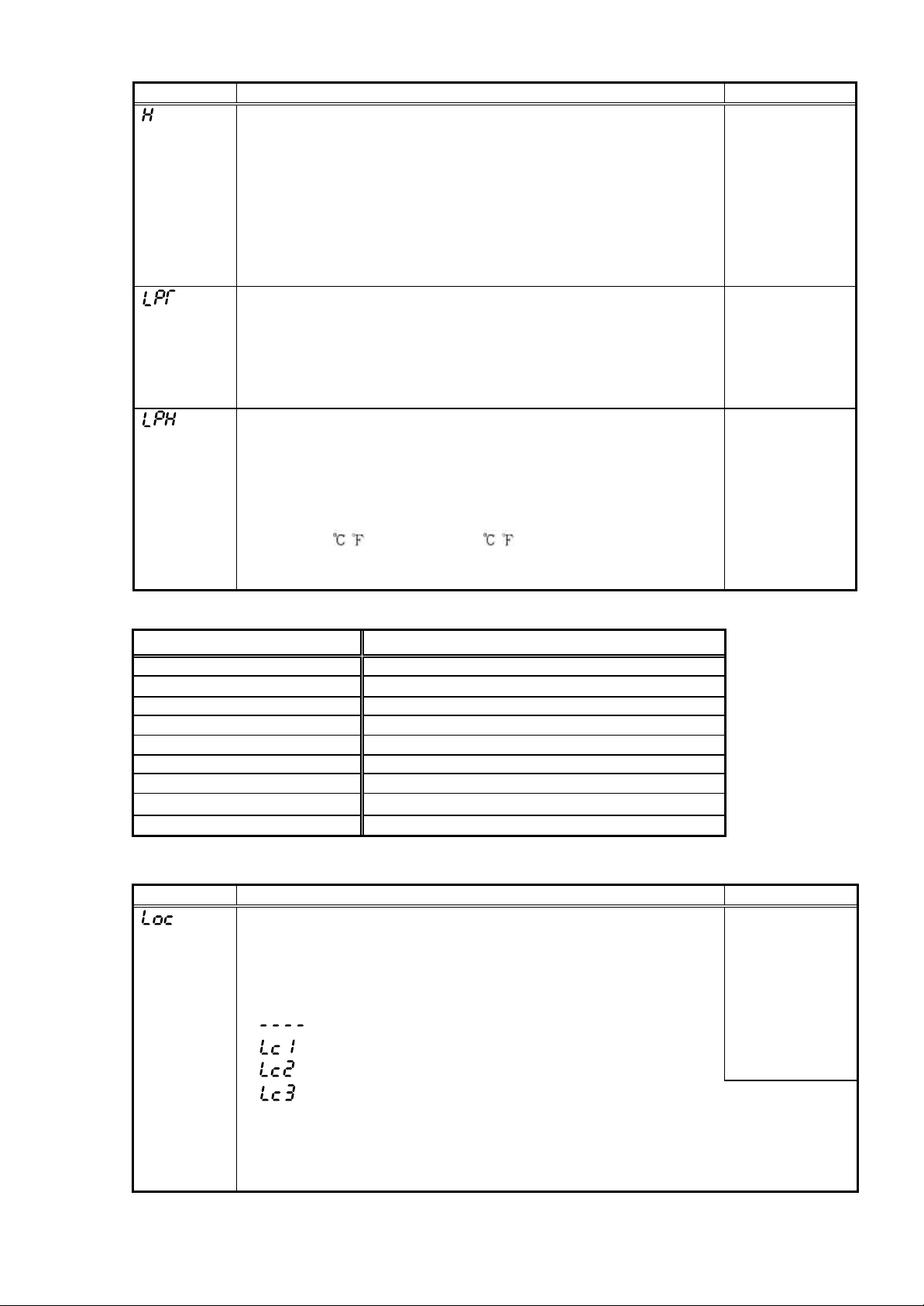
Character Name, Description, Setting range Initial value
Setting value LOCK designation
• Locks the setting value to prevent setting errors.
The setting item to be locked is dependent on the designation.
• PID auto-tuning cannot be carried out when Lock1 or Lock2
is selected.
• (Unlock): All setting values can be changed.
(LOCK 1): None of setting values can be changed.
(LOCK 2): Only main setting mode can be changed.
(LOCK 3): All setting values can be changed except Controller/Converter
function selection. However they return to their former value
after power is turned off because they are not saved in the
non-volatile memory. (Be sure to select LOCK 3 when using
with PC-900 [SVTC attached])
-side minimum
setting value
-199.9 or -1999
+side maximum
setting value
999.9 or 9999
Unlock
Page 6
Sensor correction setting
• Sets the sensor correction value of the sensor.
•
Thermocouple and RTD input: -100.0 to 100.0 ( )
DC voltage and DC current input: -1000 to 1000 (Decimal point
place follows the selection.)
Instrument number setting
• Sets the instrument number individually to each instrument
when connecting multiple instruments via serial communication.
• This setting item is indicated only when [Option: C5] is added
• 0to95
Data transfer rate selection
• Selects the data transfer rate to meet the rate of host computer.
• This setting item is indicated only when [Option: C5] is added
• 2400bps: , 4800bps: , 9600bps: , 19200bps:
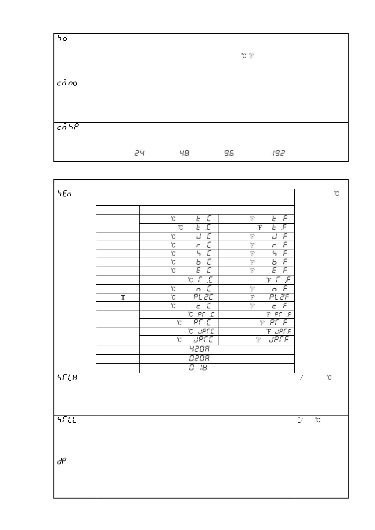
3.5 Auxiliary function setting mode 2
Character Name, Description, Setting range Initial value
• Selects the sensor type and temperature unit.
Input Character
K
J 0 to 1000 : 0to1800 :
R 0 to 1760 : 0to3200 :
S 0 to 1760 : 0to3200 :
B 0 to 1820 : 0to3300 :
E
T -199.9 to 400.0 : -199.9 to 750.0 :
N 0 to 1300 : 0to2300 :
PL- 0to1390 : 0to2500 :
C(W/Re5-26) 0to2315 : 0to4200 :
Pt100
JPt100
4to20mA
0 to 20mA -1999 to 9999:
0to1V
Scaling high limit setting
0to1370 : 0to2500 :
0.0 to 400.0
0to 800
-199.9 to 850.0 : -199.9 to 999.9 :
-200 to 850
-199.9 to 500.0 : -199.9 to 900.0 :
-200 to 500
-1999 to 9999:
-1999 to 9999:
• Sets the scaling high limit value.
• Scaling low limit
(DC voltage and current input: Decimal point place follows the
selection.)
Scaling low limit setting
• Sets the scaling low limit value.
• Input
Decimal point place selection
range minimum value to Scaling high limit setting value
(When DC voltage and DC current input- decimal point place
follows the selection.)
• Selects the decimal point place.
However, when thermocouple or RTD input is selected in
sensor selection, this setting item is not indicated.
• No decimal point to the 3
: 0.0 to 750.0 :
: 0to1500 :
: -300 to 1500 :
: -300 to 900 :
setting value to Input range maximum value
rd
digit after decimal point
0.0°C
0
9600bps
K (0 to 1370 )
M: 1370
M: 0
Decimal
point omitted
Page 7

Character Name, Description, Setting range Initial value
PV filter time constant setting
0.0 seconds
• Sets the PV filter time constant.
If the setting value is too large, it affects control result due to
the response delay.
• 0.0 to 10.0 seconds
Control output high limit setting
100%
• Sets the control output high limit value.
• This setting item is not indicated when
ON/OFF action.
• Control output low limit to 105%
Setting greater than 100% is effective to DC current output type
Control output low limit setting
0%
• Sets the control output low limit value.
• This
setting item is not indicated during ON/OFF action.
• -5% to control output high limit
Setting less than 0% is effective to DC current output type.
Control output ON/OFF action hysteresis setting
• Sets the ON/OFF action hysteresis for the control output.
• This setting item is indicated only for ON/OFF action (P=0)
• Thermocouple and RTD input: 0.1 to 100.0°C (°F)
DC voltage and current input: 1 to 1000
(Decimal point place follows the selection.)
Alarm action selection
• Selects alarm action type.
No alarm :
High limit alarm :
Low limit alarm :
High/Low limits alarm :
High/Low limit range alarm :
Process high alarm :
Process low alarm :
High limit alarm w/standby :
Low limit alarm w/standby :
High/Low limits alarm w/standby :
Alarm action Energized/Deenergized
• Selects alarm action Energized/Deenergized.
•
This setting item is not indicated when “No alarm” action is
selected in [Alarm action selection].
• Energized:
Deenergized:
Alarm HOLD function selection
• Selects whether alarm HOLD function is [Used] or not.
If alarm HOLD function is set to used, once the alarm
functions alarm output remains until the power is turned off.
•
This setting item is not indicated when “No alarm” action is
selected in [Alarm action selection].
• Alarm HOLD [Not used]:
Alarm HOLD [Used] :
Alarm hysteresis setting
• Sets the alarm hysteresis.
•
This setting item is not indicated when “No alarm” action is
selected in [Alarm action selection].
• Thermocouple and RTD input : 0.1 to 100.0°C (°F)
DC voltage and DC current input: 1 to 1000 (Decimal point
place follows the selection.)
1.0°C
No alarm
Energized
Alarm HOLD
[Not used]
1.0°C
Page 8

Alarm action delayed timer setting
• Sets the alarm action delayed time. Alarm output activates
when the setting time has passed after the input enters alarm
output range.
•
This setting item is not indicated when “No alarm” action is
selected in [Alarm action selection].
• 0to9999seconds
Direct/Reverse selection
• Selects reverse (heating) or direct (cooling) control action.
• Reverse
Direct (Cooling) action :
AT bias setting
(Heating) action:
• Set the PID auto-tuning bias value.
• This setting item is not indicated when DC voltage or current
input is selected in [Sensor selection] and when action is not
PID, either.
• 0 to 50°C (0 to 100°F) or 0.0 to 50.0°C (0.0 to 100.0°F)
Setting value digital transmission bias setting
• The desired value is the value that adds the one set in the
setting item to the received value by setting value digital
transmission.
•
This setting item is indicated only when [Option: C5] is added.
• ±20% of scaling span (DC voltage and DC current: Decimal
point place follows the selection.)
Controller/ Converter function selection
• Selects controller or converter function.
• This setting item is indicated only when the control output
is DC current output type.
• Controller function:
, Converter function:
0 seconds
Reverse
(Heating) action
20°C
0
Controller
function
Sensor correction function
This corrects the input value from the sensor. When a sensor cannot be set at a location where control
is desired, the sensor measuring temperature may deviate from the temperature in the
When controlling with multiple controllers, the accuracy of the sensors has influence on the control.
Therefore
In such case the control can be set at the desired temperature by shifting the input value of the sensors.
Loop break alarm
The alarm will be activated when the process variable (PV) does not rise as much value as the span or
greater within the time it takes to assess the Loop break alarm after the manipulated variable has re
0% or the output low limit value. When the control action is Direct (Cooling), the alarm acts conversely.
Energized/Deenergized function
[If temperature alarm action Energized is selected]
When the alarm output indicator is lit, the alarm output (between terminal 8 and 9) is conducted (ON).
When the alarm output indicator is unlit, the alarm output is not conducted (OFF).
[If temperature alarm action Deenergized is selected]
When the alarm output indicator is lit, the alarm output (between
When the alarm output indicator is unlit, the alarm output is conducted (ON).
High limit alarm (Energized setting) High limit alarm (Deenergized setting)
ON
Alarm hysteresis
ON
Alarm hysteresis
OFF
Main setting
•¢
(Fig. 3.5-1)
+Alarm setting point
OFF
Main setting
•¢
+Alarm setting point
(Fig. 3.5-2)
Page 9

3.6 Control output manipulated variable indication
Name and Description
Control output manipulated variable indication
Press the key for approx. 3 seconds during PV/SV indication mode.
Keep pressing the key until the output manipulated variable shows up, though the main
setting mode appears during the process.
(The control output manipulated variable is indicated on the SV display and the decimal point at
the second digit blinks in 0.5 seconds cycle.)
Pressing the key again, it reverts to the PV/SV mode.
4. Converter function
The converter function of this instrument converts each input (Thermocouple, RTD, DC voltage and
DC current input) value to 4 to 20mA and outputs taking advantage of the control parameter of the controller.
When this instrument is used as a converter, follow the process (1) to (7) described below.
When the process (1) to (7) is finished, this can be used as a converter.
(1): Wire and connect this instrument. (Power, Input and Output)
(2): Turn the power of this instrument ON.
(3): Call the “Secure Menu" by pressing the and key (for approx 3s).
(4): Select the sensor type from “Sensor selection ( )”.
(5): Set the high limit of the value which is going to be converted from “Scaling high limit setting ( )".
(6): Set the low limit of the value which is going to be converted from “Scaling low limit setting ( )”.
(7): Select converter (
• Outputs the input from scaling low limit setting value to high limit value in 4 to 20mA.
The ratio of the changing quantity resolution is 1 to 1000 to scaling span.
• When functioning alarm action by Converter function, set the alarm action to Process
alarm action.
If converter function is selected from “Controller/Converter function selection” in the Secure Menu, the
parameter below is automatically set. (Table 4.1-1).
) from “Control/ Converter” function selection ( )”.
But this is applied only to the DC current output type.
(Table 4.1-1)
Setting item Setting value Setting item Setting value
Main setting Scaling low limit Alarm setting 0
Proportional band setting 100.0% Loop break alarm time setting 0 seconds
Integral time 0 seconds Loop break alarm action span 0
Derivative time 0 seconds Direct/Reverse action selection Direct action
Manual reset setting 0.0
• How to fine-tune DC current output (4 to 20mA)
Carry out zero, span adjustment from zero side several times.
Carry out adjustment set by manual reset.
(1) Input the value so that the same scaling low limit value may be indicated on the PV display.
(2) Adjust the value so that the DC current output value may become 4mA by increasing
Carry out adjustment of span in the proportional band
(1) Input the value so that the same scaling high limit value may be indicated on the PV display.
(2) Adjust the value so that the DC current output value may become 20mA by increasing
Caution
and decreasing manual reset value. Output decreases when manual reset value is set
to+ side, on the other hand output increases when it is set to – side.
and decreasing manual reset value. Output decreases when proportional band value
is set to + side, on the other hand output increases when it is set to – side.
When shifting from converter function to controller function, the control parameter and values set by
converter function are held as they are even if the function is switched to controller function.
So, correct the control parameter and values set by converter function to the value necessary to the
controller function after switching to the controller function.
Page 10

5. Running
When mounting and wiring to the control panel (DIN rail) are finished, running starts following the next
procedure.
(1) Turn the power supply to the SCZ10-ON.
For approx. 3s after power on, the character of the sensor type and temperature unit are indicated
on the PV display, and the rated maximum value is indicated on the SV display. See [Table 3.1-1].
(If any other value is set at the main setting value high limit setting, SV display indicates it.)
During this time, all outputs and LED indicators are in their OFF status.
After that PV display indicates actual temperature and SV display indicates the main setting value.
(2) Input the setting value.
Input each setting value referring to “3. Operation”.
(3) Turn the load circuit power ON.
Starts control action so as to keep temperature of the controlled object at the main setting value.
6. Other functions
(1) Power failure countermeasure.
Backs up the setting data in non-volatile IC memory.
(2) Self diagnosis
The CPU is monitored by a watchdog timer and when any abnormal status is found on the CPU,
the controller is switched to warm-up status.
(3) Automatic cold junction temperature compensation (Only thermocouple input)
Detects the temperature at the connection terminal between thermocouple and instrument and
keeps it on the same status at which the reference junction is located at 0°C (32° F).
(4) Sensor burnout (Burnout)
When thermocouple or RTD input is burnt out, control output is turned OFF (DC current output
type: control output low limit) and “ ” blinks on the PV display.
When DC voltage and DC current input are burnt out, the status is as follows.
When DC current input (4 to 20mA) and DC voltage input (1 to 5V) are burnt out “ ” blinks
on the PV display.
When DC voltage input (0 to 1V) is burnt out, “ ” blinks on the PV display.
When DC current input (0 to 20mA) is burnt out, the same value at 0mA is indicated.
When DC current input (0 to 10V) is burnt out, a value close to 0V is indicated.
(5) Input burnout indication
Thermocouple, RTD input
If the PV value exceeds [input range high limit + (50°C or 100°F)], “ ” blinks on the PV display
and control output is turned OFF (DC current output type: control output low limit setting value).
However, in the case of the range with a decimal point when PV exceeds 999.9°C(°F) “ ” blinks
and control is carried out until the value becomes [Input range high limit + (50°C or 100°F)] or greater.
DC voltage and current input
If the PV value exceeds [scaling high limit value + (scaling span x 10% or greater)], “ ” blinks
on the PV display and the control output is turned OFF (DC current output type: control output low
limit setting value).
However, when PV value exceeds 9999, “ ” blinks on the PV display and control is carried out
until the value becomes [Scaling high limit + (scaling span x 10%)] or greater.
Thermocouple input
If the PV value exceeds [input range high limit - (50°C or 100°F)], “ ” blinks on the PV display
and control output is turned OFF (DC current output type: control output low limit setting value).
However, in the case of the range with a decimal point when PV exceeds -199.9°C(°F), “ ”
blinks and control is carried out until the value becomes [-199.9 - (50°C or 100°F)] or less.
RTD input
If the PV value exceeds [Input range low limit – (input span x 1)] “ ” blinks on the PV display
and control output is turned OFF (DC current output type: control output low limit setting value).
However, in the case of the range with a decimal point when PV exceeds -199.9°C (°F) “ ”
blinks and control is carried out until the value becomes [-199.9 - (input span x 1%)] or less.
DC voltage and current input
If the PV value exceeds [Scaling low limit value – (scaling span x 1%)] “ ” blinks on the PV
display and control output is turned OFF (DC current output type: control output low limit setting value).
However if the PV value exceeds –1999, “ ” blinks on the PV display and control is carried out until
the value becomes [Scaling low limit value setting value – (scaling span x 1%)] or less.
Page 11

7. Action explanations
7.1 Standard action
Action Heating (reverse)action
Proportional band
ON
Control action
OFF
Main setting
Relay contact
output
Non-contact
voltage output
Current output
Indicator (OUT)
Green
3
4
Cycle action according to deviation
+
3
-
4
Cycle action according to deviation
3
+
20mAdc 20 to 4mAdc 4mAdc 4mAdc 4to20mAdc 20mAdc
-
4
Cycle action according to deviation
Lit Unlit
3
4
3
+
-
4
3
+
-
4
Cooling (direct)action
Proportional band
ON
OFF
Main setting
3
4
+
3
0Vdc 0Vdc12/0Vdc
-
4
3
+
-
4
3
4
Cycle action according to deviation
+
3
-
4
Cycle action according to deviation
3
+
-
4
Cycle action according to deviation
Unlit Lit
3
4
+
3
0/12Vdc12Vdc 12Vdc
4
-
3
+
4
-
+
-
+
-
3
4
3
4
3
4
part: Acts ON or OFF
7.2 ON/OFF action
Action
Control action
Relay contact
output
Non-contact
voltage output
Current output
Heating (reverse) action
ON
OFF
3
4
+
3
12Vdc
-
4
+
3
20mAdc
-
4
Hysteresis
Main setting
+
+
-
3
4
-
3
4
3
4
4mAdc
0Vdc
Main setting
3
4
+
3
0Vdc
-
4
+
3
4mAdc
-
4
Cooling (direct) action
Hysteresis
+
3
-
4
+
-
ON
OFF
3
4
12Vdc
3
20mAdc
4
Indicator(OUT)
Green
part: Acts ON or OFF.
Lit Unlit
Unlit Lit
Page 12

7.3 Alarm action
Alarm
action
Alarm
output
Alarm
action
Alarm
output
Alarm
action
Alarm
output
High limit alarm
ON
OFF
- Alarm setting
point
+ side
-side
High/Low limit range alarm
ON
OFF
Alarm setting
point
High limit alarm w/standby High/Low limit range alarmLow limit alarm w/standby
ON
OFF
- Alarm setting
point
+ side
-side
High/Low limits alarm
Alarm setting
point
Main
setting
Alarm hysteresis
+ Alarm setting
point
Alarm hysteresis
ON
OFF
- Alarm setting
point
Low limit alarm
+ Alarm setting
Main
setting
ON
OFF
point
+ side
-side
Process high alarm
Alarm hysteresis Alarm hysteresis Alarm hysteresis
ON
Alarm setting
Main
setting
Main
setting
point
Alarm hysteresis Alarm hysteresis Alarm hysteresis
+ Alarm setting
point
OFF
ON
OFF
- Alarm setting
point
Alarm setting
point
Main
+ Alarm setting
setting
ON
OFF
point
Process low alarm
ON
OFF
Alarm setting
point
Alarm setting
point
+ side
-side
Main
setting
Main
setting
Alarm hysteresis
Alarm setting
point
Alarm setting
point
:Event (EVT) output terminal 8 and 9 is ON
:Event (EVT) output terminal 8 and 9 is ON or OFF
:Event (EVT) output terminal 8 and 9 is OFF
: Standby function works here.
Event (EVT) output indicator lights when output terminal between 8 and 9 is ON, goes out when OFF
7.4 Heater burnout alarm action
ON
Heater burnout
Alarm action
Indication
(HB)
Red
OFF
Heater burnout alarm
setting point
Load current
LargeSmall
UnlitLit
:Event(EVT)output terminal between 8 and 9 is ON
:Event(EVT)output terminal between 8 and 9 is OFF
Event (EVT) output indicator lights when output terminal between 8 and 9 is ON, goes out when
Page 13

8. PID auto-
In order to decide each P, I, D value and ARW automatically, this system gives a fluctuation
to the controlled object to get a optimal value.
3 types of fluctuation below are automatically selected.
[ When the difference between setting value and processing temperature is large in rising]
When AT bias is set to 20°C(°F)), a fluctuation is given at the temperature 20°C(°F
tuning of the SCZ10
Temp.
Setting
value
Temperature 20°C(°F) lower
than the setting value
(4)
AT
(1) (2) (3)
[When control is stable]
A fluctuation is given at the setting value.
Temp.
Setting
value
Time
(1):
Calculating PID constant
(2):
PID contatnt calculated
Controlled by the PID
(3):
constant set by auto-tuning.
(4):
AT bias setting value
:
Auto-tuning starting point
AT
(1):
Calculating PID constant
(2):
PID constant calculated
Controlled by PID constant
(3):
set by auto-tuning
:
AT Auto-tuning starting point
AT
Time
(1) (2) (3)
[ When the difference between the setting value and processing temperature is large when
temperature falls]
When AT bias is set to 20°C(°F), a fluctuation is given at the temperature 20°C(°F)( higher than the
Temp.
Temperature 20
°C(°F) higher
than the setting value
(1): Calculating PID constacnt
(2): PID constant calculated
(3):
Controlled by PID constant
Setting
value
(4)
set by auto-tuning
(4): AT bias setting value
:AT Auto-tuning starting point
TimeAT
(1) (2) (3)
Page 14

9. Mounting to the control panel
9.1 Site selection
[Use this instrument in the following environment (IEC61010-1)]
• Overvoltage category , Pollution degree 2
[Use this instrument under the conditions below.]
• A minimum of dust, and an absense of corrosive gasses
• No flammable, expolsive gasses
• Few mechanical vibrations or shocks
• No exposure to direct sunlight, an ambient temperature of 0 to 50 (32 to 122 )
• An ambient non-condensing humidity of 35 to 85%RH or less
• The units away from large capacity electromagnetic switches or cables
• No water, oil or chemicals or where the vapors of these substances can come
into direct contact with the unit.
9.2 External dimension
(Fig.9.2-1)
9.3 CT (Current transformer) External dimension
15.0
(0.413)
(0.590)
21.0
(0.827)
40
(1.575)
0.5
(0.020)
3.0
7.5
(0.295)
25.0
(0.984)
(0.118)
φ 5.8
(0.228)
10.5
CTL-6-S (for 20A)
30.0
(1.181)
2-φ 3.5
(0.138)
2.8
(0.110)
10.0
(0.394)
30.0
(1.181)
40
(1.575)
30.0
(1.181)
100.0
(3.937)
40.0
(1.575)
φ 12.0
15.0
(0.472)
(0.590)
CTL-12-S36-10L1 (for 50A)
(Fig.9.3-1)
9.4 Mounting to DIN rail
Caution
Mount the DIN rail horizontally.
When DIN rail is mounted vertically, be sure to use commercially available fastening plates at the end of
SCZ10. Mount the SCZ10 to the DIN rail so that the SCZ10
However, if the DIN rail is mounted horizontally in a position susceptible to vibration or shock, the fastening
plates must be used as well.
cannot move.
Page 15

* Recommended fastening plate
Omron corporation End plate PFP-M
IDEC corporation DIN rail stops BNL6, BNL8
Matsushita electric works, LTD Fastening plate ATA4806
(1) Hook (1) of SCZ10 on the upper side of the DIN rail. (Fig. 9.4 -1)
(2) Making the (1) part of the SCZ10 as a support, fit the lower part of the SCZ10 to the DIN rail.
SCZ10 will be completely fixed to DIN rail with a “Click” sound. (Fig.9.4-1)
(1)
(2)
(Fig.9.4-1)
10. Wiring
Warning
Turn the power supplied to the instrument OFF before wiring or checking.
Working or touching the terminal with the power switched ON may result in an Electric
Shock which could cause severe injury or death.
Caution
• Do not drop wire chips into SCZ10 when wiring, because they could cause fire, malfunction and trouble
• Insert the connecting cable into the designated connector securely to prevent malfunction, or it
may cause malfunction due to imperfect contact.
• Connect the AC power wiring to the designated terminal as is written in this Instruction manual, or
it may burn and damage
• Tighten the terminal screw with the specified torque,
• Use thermocouple and compensating lead wire that fit sensor input specification of this unit.
• Use 3-wire RTD that fits sensor input specification of this unit.
• Do not
• Keep input wire (Thermocouple, RTD) away from power source and load wire when wiring.
• To prevent the unit from harmful effects of the unexpected level noise, it is recommended that a
surge absorber to be installed between the electromagnetic switch coils.
• This
near the external unit.
confuse the polarity when using DC voltage and current input in the case 24Vdc is used.
unit has neither built-in power switch nor fuse. Therfore it is necessary to install them in the circuit
(Recommended fuse: Rated voltage 250Vac-Rated current: 2A-Fuse type: Time-lag fuse)
SCZ10.
Page 16

*Note
Tighten the terminal screw properly referring to the table below.
Terminal screw Terminal No. Torque
M2.6 (1) to (4) Max. 0.5N- m
M2.0 (5) to (9) Max. 0.25N- m
• Terminal arrangement
Power
24Vdc
+-
(1) (2)
+-
(3) (4)
SCZ10-2 (Switched V)
SCZ10-3 (4~20 mA)
24Vac or
100 to 240Vac
SCZ10-1 (Relay)
(1) (2) (3) (4)
(8) (9)(5) (6) (7)
+-+-
TC
(5) (6) (7)
ABB
RTD
(5) (6) (7)
Vdc
•{ •|
mAdc
Event output
(EVT)
• Event output (Open collector output)
Outputs when alarm, Loop break alarm or
Heater burnout alarm [Option] is ON.
Lower part of main body
SCZ10- 1 RS-485
Communication Ports
SCZ10- 1 Heater
Burnout CT Connection
(Fig.10-1)
(8) (9)
+-
(1) (6)
(1)
COM
(2)
NC
(3)
YA(-)
(4)
YB(+)
(5)
NC
(6)
COM
RJ-14 Wiring
for RS-485
(Fig.10-2)
• Option: Heater burnout alarm output
This alarm is not available for detecting current under
phase control.
Use the current transformer (CT) provided, and pass
CT
a lead wire of the heater circuit into a hole of the CT.
When wiring, keep the CT wire away from any AC
source or load wires to avoid the external interference.
Heater
(Fig.10-3)
11. Specifications
11.1 Standard specification
Model name DIN rail mounting type indicating controller
Mounting method DIN rail mounting method
Setting method Membrane sheet key
Display PV display: Red LED 4-digit Character size: 7.5 x 4.1mm (H x W)
SV display: Green LED 4-digit Character size 7.5 x 4.1mm (H x W)
CT input socket
Power
supply
Page 17

Input Thermocouple: K, J, R, S, E, T, N, PL-II , C (W/Re5-26) External resistance: 100Ω or less
B thermocouple: External resistance: 40Ω or less
RTD : Pt100, JPt100 3-wire system
Allowable input wire resistance (10Ω or less per wire)
DC current : 0 to 20mAdc, 4 to 20mA input impedance 50Ω
[Connect 50Ω shunt resistor (sold separately) between input terminal (5) and (6).]
Allowable input current: 50mA or less
DC voltage : 0 to 1Vdc
Input impedance: 1MΩ or greater
Allowable input voltage: 5V or less
Allowable signal source resistance
:2kΩ or less
Accuracy (Indicating
• Setting)
Thermocouple input: Within ±0.2% of input span ±1 digit or ±2°C (4°F) whichever is greater.
R, S input 0 to 200°C (0 to 400°F): Within ±6°C (2°F).
B input 0 to 300°C (0 to 600°F): Accuracy is not guaranteed.
RTD input: Within ±0.1% of input span ±1 digit or within ±1°C (2°F) whichever is greater.
DC voltage input : Within ±0.2% of input span ±1 digit
DC current input : Within ±0.2% of input span ±1 digit
Input sampling period : 0.25 seconds
Control Control action
• PID action (with auto-tuning function)
• PI action : When derivative time is set to 0
• PD action (with manual reset function): When integral time is set to 0
• P action (with manual reset function) : When derivative and integral time are set to 0
• ON/OFF action : When proportional band is set to 0
Proportional band: 0.0 to 110.0% [Factory adjusted as 2.5%]
(ON/OFF action when set to 0.0)
Integral time : 0 to 1000 seconds (Off when set to 0) [Factory adjusted as 200 seconds]
Derivative time : 0 to 300 seconds (Off when set to 0)[Factory adjusted as 50 seconds]
Proportional cycle : 1 to 120 seconds [Factory adjusted as Relay: 3/ sec.; SS: 3 sec.]
ARW : 0 to 100% [Factory adjusted as 50%]
Manual reset : ±Proportional band converted value [Factory adjusted as 0.0]
Output limit : 0 to 100% (DC current output type: -5 to 105%)
(Not available for ON/OFF action)
[Factory adjusted as control output low limit setting value 0%
control output high limit setting value100%]
Hysteresis : Thermocouple and RTD input: 0.1 to 100.0°C (°F)
[Factory adjusted as 1.0°C]
DC voltage and current input: 1 to 1000
(Decimal point place follows the selection.)
[Factory adjusted as 10]
Control output (OUT)
• Relay contact : Control capacity 250Vac 3A (Resistive load)
250Vac 1A (Inductive load COS φ = 0.4)
Electric life 100,000 cycles
• Non-contact voltage (for SSR drive): 12
--
Vdc Max. 40mA (Short-circuit protected)
--
• DC current: 4 to 20mAdc, Load resistance: Max. 550Ω
Output accuracy: Within ±0.3% of output span
Resolution : 12000
Alarm Alarm (EVT) output (Common output with Loop break alarm, Heater burnout
alarm [optional])
When input exceeds the range in ± deviation setting (excluding Process alarm) to the main
setting, alarm (EVT) turns ON or OFF (High/Low limit range alarm), and when Deenergized
is selected in Energized/Deenergized selection, alarm (EVT) is activated conversely.
Page 18

Setting accuracy: The same as indicating accuracy
Action: ON/OFF action
Hysteresis: T/C and RTD input: 0.1 to 100.0°C (°F) [Factory adjusted as 1.0°C]
DC voltage and current input: 1 to 1000 [Factory adjusted as 10]
(Decimal point place follows the selection.)
Output: Open collector, 24Vdc @ 0.100A maximum.
Alarm (EVT) output action: Alarm action is selectable from below by front key operation.
One alarm is selectable from High limit, Low limit,
High/Low limits, High/Low limit range, Process high,
Process low, High limit w/standby, Low limit w/standby,
High/Low limits w/standby and No alarm action
[Factory adjusted as No alarm action]
Energized/Deenergized: Alarm (EVT) output Energized/Deenergized can be selected.
[Factory adjusted as Energized]
Energized Deenergized
Red (EVT) LED Lights Lights
Alarm output ON OFF
Alarm HOLD function selection: Once the alarm is activated, alarm output is remains
constant until power is turned off.
[Factory adjusted as: Alarm holding function Not used]
Loop break alarm (EVT) output is common with Alarm and optional Heater Burnout Alarm.
Detects heater burnout, sensor burnout, and abnormality at operation end.
Setting range: Loop break alarm time setting: 0 to 200 minutes
[Factory adjusted as 0 minutes]
Loop break alarm action span setting
Thermocouple and RTD input: 0 to 150°C (°F) or 0.0 to 150.0 °C (°F)
[Factory adjusted as 0°C
DC voltage and current input: 0 to 1500
[Factory adjusted as 0]
(Decimal point place follows the selection.)
Output: Open Collector, 24Vdc @ 0.100A maxilmum.
Converter function: See Section 1, "Converter Function."
Insulation
• Dielectric strength Circuit insulation structure
(8) (9)
Event output
Control outputPower supply
CT input
Communication
(5) (6) (7)
Input
CPU
Insulation
(1) (2) (3) (4)
Insulated resistance: 10MΩ or greater @ 500 Vdc except as noted above.
Dielectric strength: 1.5kVac for 1 minute between input terminal and power
terminal.
Power consumption Approx. 6VA
Ambient temperature 0 to 50°C (32 to 122°F)
Ambient humidity 35 to 85%RH (Non condensing)
Weight Approx.150g (5.3 oz.)
* When controls output is noncontact voltage of DC Current,
there is no isolation between
the control output and the
communications option.
Page 19

External dimension 22.5 x 75 x 100mm (W x H x D)
Material Case: Flame resistant resin
Color Case: Light gray
Attached function Sensor correction, Setting value lock, Power failure countermeasure,
Accessories Instruction manual: 1 copy
When [Option: W] is added
Wire harness 3m : 1 set
W (5A), W (10A), W (20A): Current transformer: CTL-6S 1 set
W (50A) : Current transformer: CTL-12-S36-10L1 1 set
11.2 Optional specification
Heater burnout alarm output
Watches the heater current with CT (current transformer) and detects burnout.
When this option is added, the alarm output and Loop break alarm share a common output.
This option cannot be applied to the current output type.
Rating : 5A, 10A, 20A, 50A, by order code.
Setting range : 5A, 0.0 to 5.0 A (Off when set to 0.0)
Setting accuracy: :±5% of the rated value
Action : ON/OFF action
Output : Open collector, 24 Vdc @ 0.100A maximum.
Self-diagnosis, Automatic cold junction compensation, Burnout, Input burnout
:10A, 0.0 to 10.0A (Off when set to 0.0)
:20A, 0.0 to 20.0A (Off set to 0.0)
:50A, 0.0 to 50.0A (off when set to 0.0) set to 0.0)
Serial communication
Operates the following from the external computer.
(1) Reading and setting of main setting value, PID and each setting value
(2) Reading of input value and action status
(3) Function change
Communication circuit: Based on EIA RS-485
Communication method: Half duplex, start-stop synchronous
Data transfer rate: 2400, 4800, 9600, or 19200bps, selectable by key operation.
Data format: Start bit-----------------1
Data bit-----------------7
Parity-----------------Even
Stop bit-----------------1
Page 20

12. Troubleshooting
If any malfunctions occur, refer to the following items after checking the power supply and wiring.
Indication
Phenomenon Presumed cause and solution
“ ” is blinking on the PV
display.
The indication on the PV display
does not change.
“ ” is blinking on the PV
display.
The indication on the PV display
is abnormal or unstable.
“ ” is indicated on the
PV display.
• Sensor (Thermocouple, RTD and DC voltage
[0 to 1Vdc] input) is burnt out.
Change the sensor for new one.
• The lead wire of the sensor (Thermocouple, RTD and DC
voltage [0 to 1Vdc] input ) is not securely connected.
Connect it to the terminal properly.
• Sensor (DC current [0 to 20mAdc] and DC voltage
[0 to 10Vdc]) is burnt out.
Change the sensor for the new one.
• The lead wire of the sensor (DC current [0 to 20mAdc] and
DC voltage [0 to 10Vdc] is not securely connected to the
terminal.
Connect the sensor lead wire securely to the instrument
terminal.
• Sensor (DC current [4 to 20mAdc] and DC voltage[1 to 5Vdc]
input) is burnt out.
Change the sensor for the new one.
• The sensor lead wire is not securely connected to the
terminal (DC current
[1 to 5Vdc]
Connect the sensor lead wire securely tothe terminal of
the instrument.
4 to 20mAdc) and DC voltage
• Designation of the sensor (input) is incorrect.
Set the correct sensor (input).
• The polarity of the sensor input is incorrect.
Wire it correctly.
• Temperature unit (°C/°F) is mis-selected.
Set the correct unit.
• AC is leaking from controlled object to thermocouple or RTD.
Keep AC from leaking into the controlled object.
• Internal memory is out of order.
Please contact our sales branch or the shop where you
purchased this unit.
Key operation
Phenomenon Presumed cause and solution
• Setting values do not change
even if the or key is
pressed during setting mode
• Unable to set the value beyond
or below scaling high limit or low
limit within the rated scale range
even if the or key
is pressed.
• Mode1 or mode 2 is selected in setting value lock selection.
Cancel the Lock mode.
• PID auto-tuning is performing.
Cancel PID auto-tuning.
• The value of scaling high limit setting or low limit setting in
auxiliary function setting mode 2 is set to still one.
Set the proper value.
• If you have any inquiries, please contact us or the shop where you purchased the unit.
 Loading...