

Page 1
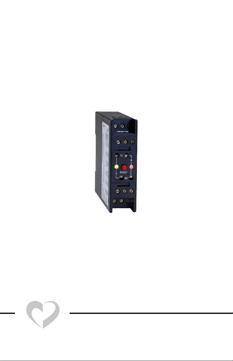
Loop Alarm™
Model SC1490 and SCL1490
INSTALLATION INSTRUCTIONS
LOVE CONTROLS
LOVE
®
December, 2004 Page 1 of 8 949-0531 Rev. 2
a Division of Dwyer Instruments, Incorporated
PO Box 338 Michigan City, IN 46361-0338
(800) 828-4588 (219) 879-8000 FAX (219) 872-9057
❍
❍
www.love-controls.com
❍
Page 2

Getting Started
1.) Using a small screwdriver, ball point pen, etc. set the Input Switch
(SW-1) on the side of the unit for the input range to be used.
2.) Set the Output Switch (SW-2) for the output responses required (see
Output Programming on page 4).
3.) Mount unit into panel. (see Mounting on page 5).
4.) Connect unit to input signal, output signal, and power wiring (see Wiring on page 5).
5.) Check calibration (See Calibration on page 6).
Operation description is on page 6
Specifications are on page 7.
Copyright © 2004 Love Controls Division, Dwyer Instruments, Inc. All rights reserved.
949-0531 Rev. 2 Page 2 of 8 December 2004
Page 3
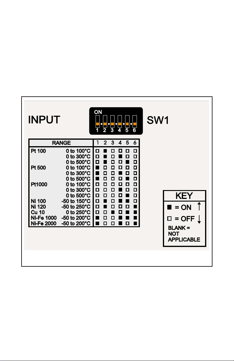
INPUT PROGRAMMING
Switches 1 through 6 on SW1 allow selection for RTD type.
Use the chart (Figure 1, below) to select the input type and range for your
process. Turn on the appropriate switch(s) (as indicated) on SW1 for the
input range desired.
Figure 1
December, 2004 Page 3 of 8 949-0531 Rev. 2
Page 4

OUTPUT PROGRAMMING
Since the alarms can be set for reverse or direct action, high or low
function, and has normally open and normally closed contacts; the
number of combinations of actual output behavior is quite large.
First, decide how you want the outputs to behave. Will the relay
energize or de-energize at the trip point? Will the relay trip on an
increasing or decreasing signal? Is the dead band above or below
the trip point?
It is important to answer these questions before setting up the module. The following Function Chart illustrates the most likely combinations of settings.
Function Chart
Figure 2
Using the Figure 3 (next page), set up the switches on SW2 for
Alarm A and Alarm B. For dual alarm relays triggered by
Alarm A, set switch 5 to DUAL. When switch 5 is set to
DUAL (on), switches 6 and 7 have no effect.
949-0531 Rev. 2 Page 4 of 8 December 2004
Page 5

Figure 3
WIRING
Mount on DIN rail and wire per Figure 5 below.
290-2888
MADE IN U.S.A.
LOVE CONTROLS
MICHIGAN CITY, IN 46361, U.S.A.
DIV. OF DWYER INSTRUMENTS, INC.
TM
MODEL:
S/N:
RTD
+
T/C,V
1
4
N.C.
ALARMA
ALARMB
N.C.
7
10
POWER
&I
INPUT
2
5
COM
COM
8
11
3
6
N.O.
N.O.
9
12
For SC1490, power is 85 to 265 Vdc/Vac 50 to 400 Hz.
For SCL1490 power is 12 to 24 Vdc/Vac 50 to 400 Hz. ±20%.
Figure 4
W ARNING: Do not attempt to operate this device with the cover removed. Potentially lethal voltage is present on some of the internal
components. Do not open the unit. There are
no internal adjustments or user serviceable
parts in the unit.
December, 2004 Page 5 of 8 949-0531 Rev. 2
Page 6

ALARM CALIBRATION
12345678
ON
1234
ON
12345678
ON
NOTE: Allow the module and socket to come to stable
temperature before proceeding. For best results, allow
the module to be powered in the socket for at least 20
minutes.
Refer to Figure 5 when using the following procedure:
1. Apply the appropriate input for the desired
alarm trip point.
2. Adjust the alarm AL screw for relay trip (LED
changes color).
3. Adjust the alarm DB screw to the full clock-
wise position. Change the input to the desired reset point. Slowly tur n the alarm DB
screw counter-clockwise until the rela y resets
(Alarm LED changes back to original color).
4. Move the input back to the desired trip point
to confirm correct setting.
5. Move the input to the reset point to confirm
correct setting.
6. Repeat as necessary.
AL
B
RESET
A
DB
Figure 5
OPERATION
On power up the module will automatically reset the alarms provided
that no alarm condition exists. It may be necessary to reset a low
alarm after the process has reached normal conditions.
When the input is within set limits, both LED indicators will be green
and the relay contacts will be in the state programmed for nor mal operation. If the input reaches either of the trip points, the relay connected to that trip point will change state and the LED connected to
that point will indicate red.
When the input returns to normal (tr ip point plus dead band for low
alarm settings, trip point less dead band for high alarm settings) and
switch 4 of SW 2 is set to NON-LATCHING, the relay and LED will
automatically return to the non-alarm condition. If switch 4 of SW 2 is
set to latching, the red RESET button on the top of the module must be
pressed to return the relay and LED to the non-alarm condition.
949-0531 Rev. 2 Page 6 of 8 December 2004
Page 7
SPECIFICATIONS
Power Supply:
SC1090: 85 to 265 Vdc/Vac 50 to 400 Hz.
SCL1090: 12 to 24 Vdc/Vac 50 to 400 Hz. ±20%
Isolation: 1500 V rms between outputs, input, and power.
Set Points: Adjustable 0 to 100% of span.
Deadband: Adjustable 0.25% to 100% of span.
Drift: ±0.02% / °C typical, ±0.05% / °C maximum.
Ambient T emperature Range:
Operating: 0° to 55° C (32° to 131° F)
Storage: -40° to +80°C (-40° to +176°F)
Humidity Conditions: 0 to 90% up to 40 °C non-condensing, 10 to 50%
at 55 °C non-condensing.
Excitation Current: Cu10Ω = 5 mA; Plt 100Ω , Ni 100Ω, Ni 120Ω =
500µA; Plt 500Ω, NiFe 1000Ω = 100 µA; Plt 1000Ω = 50 µA.
Lead Compensation Error: ≈0.02%/Ω.
Open Lead Protection: Upscale only.
Relay output: SPDT, one per set point, 5A @ 250 VAC, resistive.
Latch circuit reset: Automatic at power up. Manual with reset switch
on front of module.
Indicators: One dual color LED per set point. Red = relay on, green
= relay off.
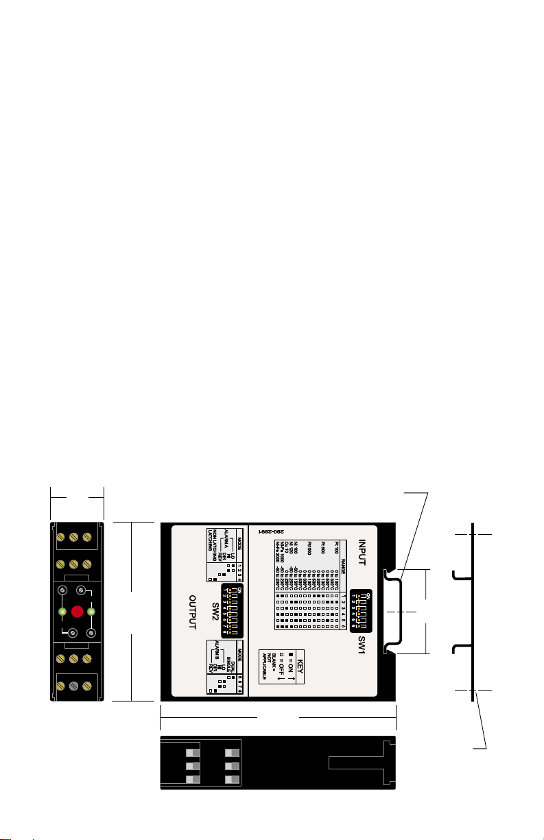
DIMENSIONS
22.5
(0.886)
AL
B
75
RESET
A
All dimensions in
millimeters (inches)
(2.950)
DB
(3.880)
9
12
8
11
7
10
December, 2004 Page 7 of 8 949-0531 Rev. 2
DIN EN 50022-35
(not supplied)
35.5
(1.40)
ADAPTER BRACKET
FOR SURFACE MOUNTING
(OPTIONAL)
KIT#: 1007-35DINADPTR
Page 8

NOTES
949-0531 Rev. 2 Page 8 of 8 December 2004
 Loading...