

Page 1

Series RHPLC Humidity/Temperature Transmitter
[1
[71.12]
1-3/32
35/64
[76.56]
®
Specications - Installation and Operating Instructions
Bulletin AQ-RHPLC
4-1/2
14.30]
The Series RHPLC Wall Mount Humidity/Temperature Transmitter is a compact
economical sensor for the building automation marketspace. The stylish housing is
well vented to provide air ow across the sensor to improve measurement accuracy.
Each unit utilizes a capacitive polymer sensing element to deliver a proportional
analog output. A combination humidity and temperature model can be congured
with current, voltage, RTD, or thermistor output. A wide selection of passive RTD or
thermistor temperature sensors are available in this series.
BENEFITS/FEATURES
• Reduced installation cost with combined humidity and temperature sensing
• Wide application environments from a large selection of temperature sensors and
2% to 3% accuracies
APPLICATIONS
• Air economizers
• Room comfort monitoring
MODEL CHART
Example RHPLC -3 N 2 A -FC RHPLC-3N2A-FC
Series RHPLC Humidity/temperature transmitter
Accuracy 2
Housing N North American style wall mount
Humidity Output 1
Temperature
Output
Options FC Factory calibration certicate (3%
3
2
3
2% accuracy
3% accuracy
Current 4-20 mA
Voltage 0-10 VDC
Voltage 0-5 VDC
0
None
1
Current 4-20 mA
2
Voltage 0-10 VDC
3
Voltage 0 to 5 VDC
A
10K Ω @ 25ºC thermistor type III
B
10K Ω @ 25ºC thermistor type II
C
3K Ω @ 25ºC thermistor
D
100 Ω RTD DIN 385
E
1K Ω RTD DIN 385
F
20K Ω @ 25ºC thermistor
accuracy units)
[27.69]
2X 11/64
[4.47]
2-51/64
SPECIFICATIONS
Sensor: Capacitive polymer.
Relative Humidity Range: 0-100% RH.
RH Accuracy: ±2% 10 to 90% RH @ 25°C for 2% accuracy units; ±3% 20 to 80%
RH @ 25°C for 3% accuracy units.
RH Hysteresis: ±0.8%.
RH Repeatability: ±0.1% typical.
Temperature Output Range: -40 to 140°F (-40 to 60°C).
Passive Thermistor Temperature Sensor Accuracy: ±0.36ºF @ 77°F (±0.2°C @
25°C).
Accuracy RTD Temp Sensor: DIN Class B; ±0.3°C @ 0°C (±0.54°F @ 77°F).
Accuracy Current/Voltage Temperature Output: ±0.9°F @ 72°F (±0.3°C @
25°C).
Temperature Limits: Operating: -40 to 140°F (-40 to 60°C); Storage: -40 to 176°F
(-40 to 80°C).
Power Requirements: 10-35 VDC for 4-20 mA or 0-5 VDC output; 15-35 VDC for
0-10 VDC output; 10-29 VAC for 0-5 VDC output; 15-29 VAC for 0-10 VDC output.
Response Time: 8 s (
Electrical Connections: Screw terminal block.
Drift: <0.25% RH/year.
Enclosure Material: Polycarbonate.
Weight: 4.4 oz (125 g).
Agency Approvals: CE.
t63).
31/64
[12.32]
[14.02]
3-1/64
DWYER INSTRUMENTS, INC.
P.O. BOX 373 • MICHIGAN CITY, INDIANA 46360, U.S.A.
Phone: 219-879-8000
Fax: 219-872-9057
www.dwyer-inst.com
e-mail: info@dwyermail.com
Page 2
INSTALLATION
Disconnect power supply before installation to prevent electrical
WARNING
Make sure all connections are in accordance with the job wiring diagram and in
accordance with national and local electrical codes. Use copper conductors only.
CAUTION
CAUTION
designed for AC voltage operation.
NOTICE
MOUNTING
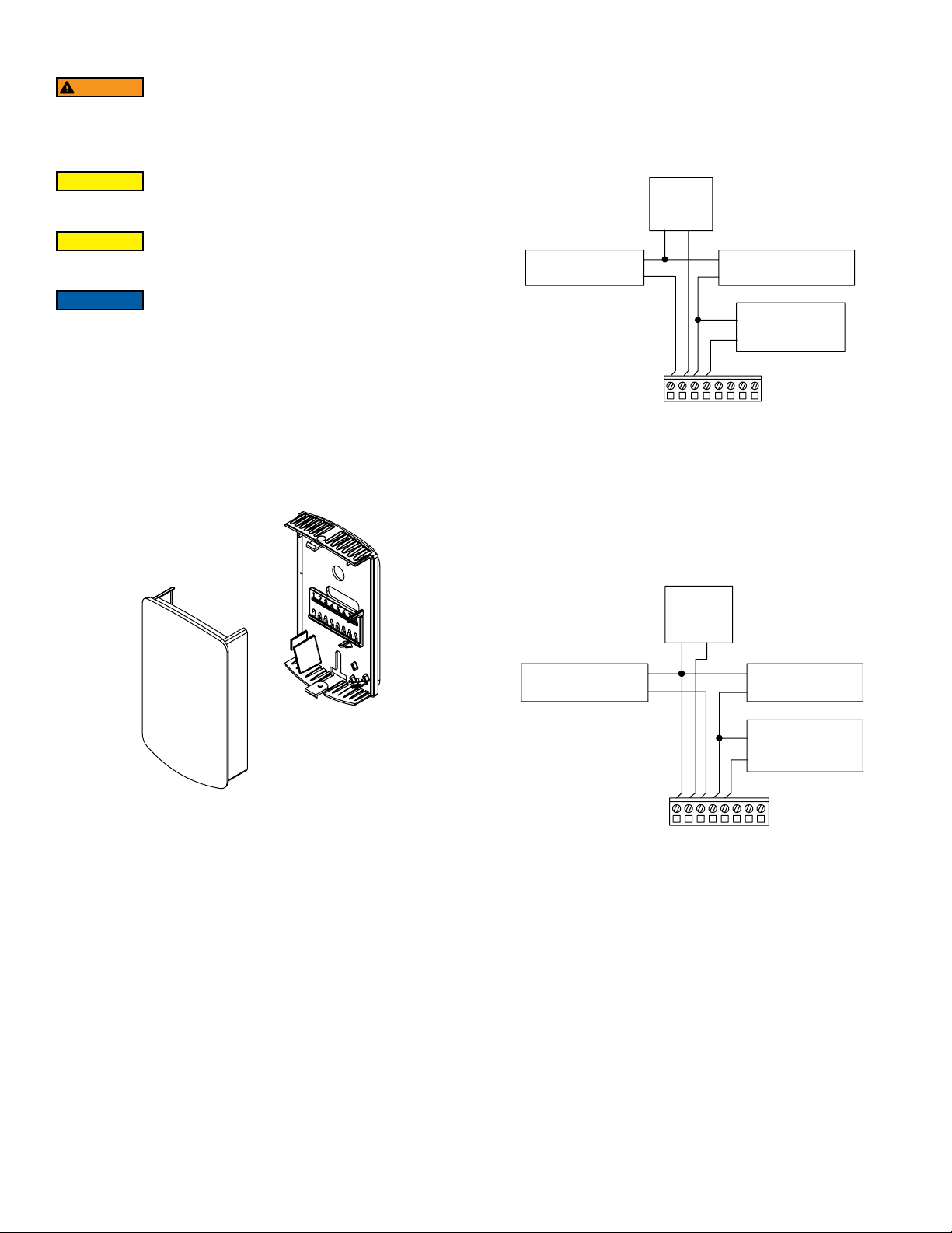
1. Push tab on top and bottom of cover and lift cover from back plate (See Figure 1).
2. Select the mounting location, away from diffusers, lights, or any external
inuences.
3. Mount transmitter on a vertical surface to a standard electrical box using the two
#6
4. M2C type screws provided.
5. Pull wires through sub base hole and make necessary connections.
6. Reattach cover to base plate
shock and equipment damage
Use electrostatic discharge precautions (e.g., use of wrist straps)
during installation and wiring to prevent equipment damage.
Do not exceed ratings of this device, permanent damage not
covered by warranty may result. The 4-20 mA models are not
Avoid locations where severe shock or vibration, excessive
moisture, or corrosive fumes are present.
Wiring
Use a minimum of 22 AWG to maximum 18 AWG wire for wiring to terminals. Refer to
Figures 2 and 3 for wiring information.
Current Output Models: Wire as shown in Figure 2. Current outputs must be powered
with 10-35 VDC. If the RH output is not required, wire the negative terminal of the
power supply to terminal 1 of the transmitter. If the unit has a passive temperature
sensor, wire to terminals 3 and 4.
POWER
SUPPLY
-
+
RH RECEIVER
4-20 mA
Voltage Output Models: Voltage outputs may be powered with 10-35 VDC (0-5 V
models), 15-35 VDC (0-10 V models) or 10-29 VAC (0-5 V modes), 15-29 VAC (0-10
V models). Note polarity when using DC power. Wire the RH voltage output as shown
in Figure 3. If the unit has a voltage temperature output, wire the temperature receiver
between terminal 4 and the negative terminal of the power supply. If the temperature
or RH voltage output is not used it may be left disconnected. If the unit has a passive
temperature sensor, wire to terminals 4 and 5.
-
+
1 2 3
Figure 2: Current output wiring
TEMP RECEIVER
4-20 mA
+
4 5 6 7 8
PASSIVE TEMP.
SENSOR
(IF PRESENT)
Figure 1: Removal of cover from back plate
RH RECEIVER
POWER
SUPPLY
-+
-
+
1 2 3 4 5 6 7 8
Figure 3: Voltage output wiring
-
+
TEMP
RECEIVER
PASSIVE TEMP.
SENSOR
(IF PRESENT)
Page 3

TROUBLESHOOTING
1. Verify that the unit is mounted in the correct position.
2. 4-20 mA Models:
Verify appropriate supply voltage. The transmitter requires a minimum of 10 and a
maximum of 35 VDC at its connections for proper operation. Choose a power supply
with a voltage and current rating which meets this requirement under all operating
conditions. If the power supply is unregulated, make sure voltage remains within these
limits under all power line conditions. Ripple on the supply should not exceed 100mV.
Loop Resistance – The maximum allowable loop resistance depends on the power
supply voltage. Maximum loop voltage drop must not reduce the transmitter voltage
below the 10 VDC minimum. Maximum loop resistance can be calculated with the
following equation. Vps is the power supply voltage.
-10.0
ps
Rmax =
V
20 mA
Some receivers, particularly loop powered indicators, may maintain a xed loop
voltage to power the device. This voltage drop must also be subtracted from the power
supply voltage when calculating the voltage margin for the transmitter. The following
equation takes this into account. Vrec is the receiver xed voltage.
-10.0-V
V
ps
Rmax =
rec
20 mA
Voltage Output Models:
Verify appropriate supply voltage. The voltage output models require a 10-35 VDC (0-5
V models), 15-35 VDC (0-10 V models) or 10-29 VAC (0-5 V modes), 15-29 VAC (0-10
V models) for proper operation maximum. Maximum output load is 5 mA.
MAINTENANCE/REPAIR
Upon nal installation of the Series RHPLC, no routine maintenance is required. The
Series CDWP is not eld serviceable and is not possible to repair the unit. Field repair
should not be attempted and may void warranty.
WARRANTY/RETURN
Refer to “Terms and Conditions of Sale” in our catalog and on our website. Contact
customer service to receive a Return Goods Authorization number before shipping the
product back for repair. Be sure to include a brief description of the problem plus any
additional application notes.
RESISTANCE VS TEMPERATURE TABLE
Temperature Resistance Curves (in Ohms)
°C °F A B C D E F
-55
-67.0
-50
-45
-40
-35
-30
-25
-20
-15
-10
-5
0
5
10
15
20
25
30
35
40
45
50
55
60
65
70
75
80
85
90
95
100
105
110
115
120
125
130
135
140
145
150
-58.0
-49.0
-40.0
-31.0
-22.0
-13.0
-4.0
5.0
14.0
23.0
32.0
41.0
50.0
59.0
68.0
77.0
86.0
95.0
104.0
113.0
122.0
131.0
140.0
149.0
158.0
167.0
176.0
185.0
194.0
203.0
212.0
221.0
230.0
239.0
248.0
257.0
266.0
275.0
284.0
293.0
302.0
607800.00
441200.00
323600.00
239700.00
179200.00
135200.00
102900.00
78910.00
61020.00
47540.00
37310.00
29490.00
23460.00
18780.00
15130.00
12260.00
10000.00
8194.00
6752.00
5592.00
4655.00
3893.00
3271.00
2760.00
2339.00
1990.00
1700.00
1458.00
1255.00
1084.00
939.30
816.80
712.60
623.60
547.30
481.80
425.30
376.40
334.00
297.20
265.10
237.00
963849.00
670166.00
471985.00
336479.00
242681.00
176974.00
130421.00
97081.00
72957.00
55329.00
42327.00
32650.00
25392.00
19901.00
15712.00
12493.00
10000.00
8057.00
6531.00
5326.00
4368.00
3602.00
2986.00
2488.00
2083.00
1752.00
1480.00
1255.00
1070.00
915.50
786.60
678.60
587.60
510.60
445.30
389.60
341.90
301.00
265.80
235.30
208.90
186.10
289154.70
201049.80
141595.50
100943.70
72804.30
53092.20
39126.30
29124.30
21887.10
16598.70
12698.10
9795.00
7617.60
5970.30
4713.60
3747.90
3000.00
2417.10
1959.30
1597.80
1310.40
1080.60
895.80
746.40
624.90
525.60
444.00
376.50
321.00
274.65
235.98
203.58
176.28
153.18
133.59
116.88
102.57
90.30
79.74
70.59
62.67
55.83
78.32
80.31
82.29
84.27
86.25
88.22
90.19
92.16
94.12
96.09
98.04
100.00
101.95
103.90
105.85
107.79
109.74
111.67
113.61
115.54
117.47
119.40
121.32
123.24
125.16
127.08
128.99
130.90
132.80
134.71
136.61
138.51
140.40
142.29
144.18
146.07
147.95
149.83
151.71
153.58
155.46
157.33
783.2
803.1
822.9
842.7
862.5
882.2
901.9
921.6
941.2
960.9
980.4
1000.0
1019.5
1039.0
1058.5
1077.9
1097.4
1116.7
1136.1
1155.4
1174.7
1194.0
1213.2
1232.4
1251.6
1270.8
1289.9
1309.0
1328.0
1347.1
1366.1
1385.1
1404.0
1422.9
1441.8
1460.7
1479.5
1498.3
1517.1
1535.8
1554.6
1573.3
2394000.00
1646200.00
1145800.00
806800.00
574400.00
413400.00
300400.00
220600.00
163500.00
122280.00
92240.00
70160.00
53780.00
41560.00
32340.00
25360.00
20000.00
15892.00
12704.00
10216.00
8264.00
6722.00
5498.00
4520.00
3734.00
3100.00
2586.00
2166.00
1822.60
1540.00
1306.40
1112.60
951.00
815.80
702.20
606.40
525.60
N/A
N/A
N/A
N/A
N/A
Page 4

NOTES
__________________________________________________________________________________________________________________________________________
__________________________________________________________________________________________________________________________________________
__________________________________________________________________________________________________________________________________________
__________________________________________________________________________________________________________________________________________
__________________________________________________________________________________________________________________________________________
__________________________________________________________________________________________________________________________________________
__________________________________________________________________________________________________________________________________________
__________________________________________________________________________________________________________________________________________
__________________________________________________________________________________________________________________________________________
__________________________________________________________________________________________________________________________________________
__________________________________________________________________________________________________________________________________________
__________________________________________________________________________________________________________________________________________
__________________________________________________________________________________________________________________________________________
__________________________________________________________________________________________________________________________________________
__________________________________________________________________________________________________________________________________________
__________________________________________________________________________________________________________________________________________
__________________________________________________________________________________________________________________________________________
__________________________________________________________________________________________________________________________________________
__________________________________________________________________________________________________________________________________________
__________________________________________________________________________________________________________________________________________
__________________________________________________________________________________________________________________________________________
__________________________________________________________________________________________________________________________________________
__________________________________________________________________________________________________________________________________________
__________________________________________________________________________________________________________________________________________
__________________________________________________________________________________________________________________________________________
__________________________________________________________________________________________________________________________________________
Printed in U.S.A. 9/21 FR# 443637-50 Rev. 1©Copyright 2021 Dwyer Instruments, Inc.
DWYER INSTRUMENTS, INC.
P.O. BOX 373 • MICHIGAN CITY, INDIANA 46360, U.S.A.
Phone: 219-879-8000
Fax: 219-872-9057
www.dwyer-inst.com
e-mail: info@dwyermail.com
 Loading...