

Page 1
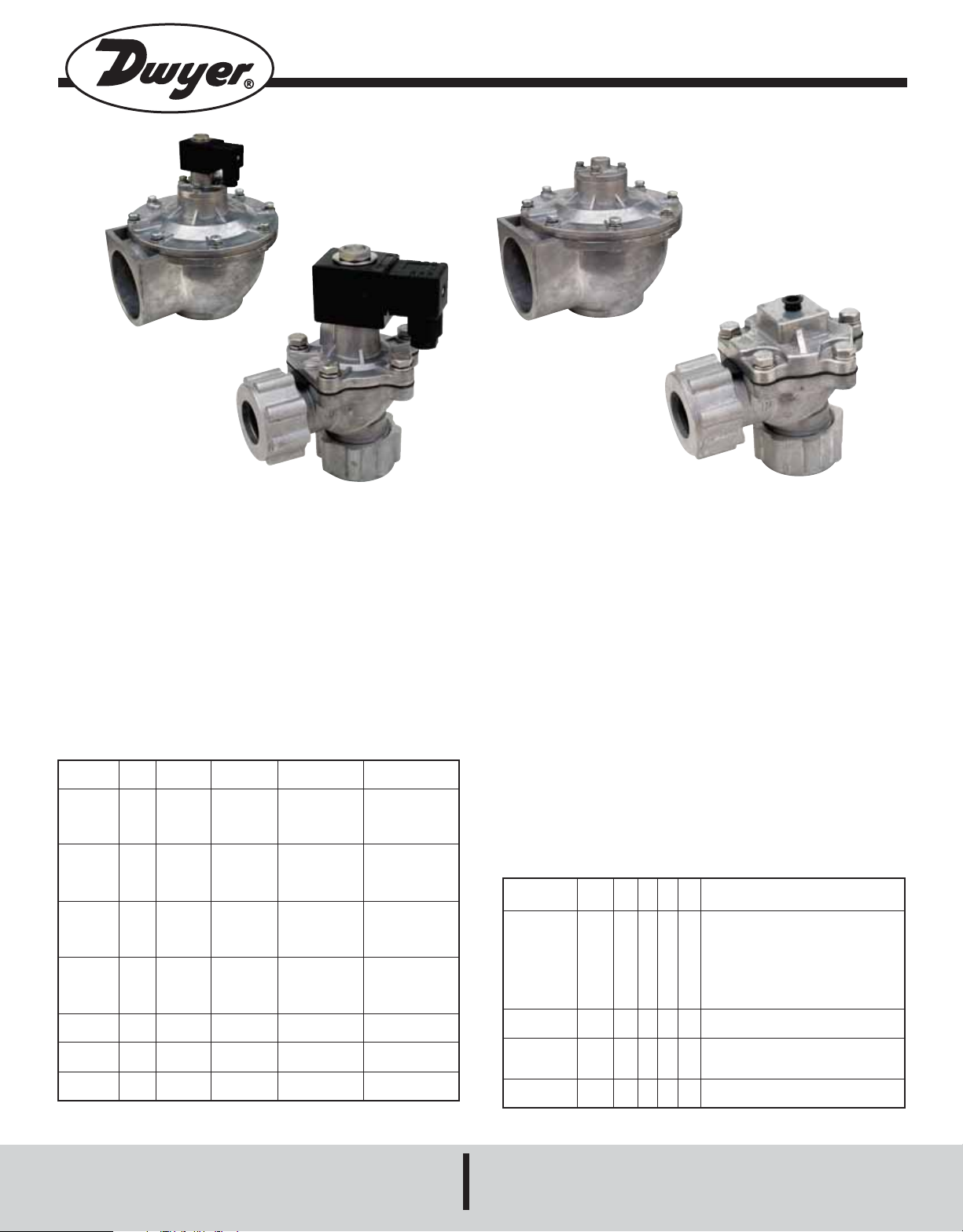
Series DCV/RDCV Diaphragm Valves
Specifications - Installation and Operating Instructions
Bulletin V-14
DCV62T1D
DCV20C1D
The Series DCV/RDCV Dust Collection Valves are ideal for use with
the Series DCT1000 and Series DCT500 duct collection timer boards.
Both the Series DCV and RDCV have the option for either coupling or
NPT connections. The coupling connection allows for a quick and simple
installation. Only the stub pipe and blowtube need to be cleaned and deburred before the valve is fit into position. The “T” Series DCV has female
threaded connections. Both the “C” and “T” versions have a 90° angle between the inlet and outlet the most suitable configuration for pulse valve
applications. The design offers not only ease of installation, but also minimal airflow restriction for an exceptional cleaning pulse. The valves are
offered in both integrated and remote coil configurations.
MODELS
Model
RDCV20T
RDCV20C
DCV20T1D
DCV20C1D
RDCV25T
RDCV25C
DCV25T1D
DCV25C1D
RDCV35T
RDCV35C
DCV35T1D
DCV35C1D
RDCV45T
RDCV45C
DCV45T1D
DCV45C1D
RDCV50T
DCV50T1D
RDCV62T
DCV62T1D
RDCV76T
DCV76T1D
Size
3/4˝
1˝
1-1/2˝
1-1/2˝
2˝
2-1/2˝
3˝
Solenoid
Remote
Remote
Integral*
Integral*
Remote
Remote
Integral*
Integral*
Remote
Remote
Integral*
Integral*
Remote
Remote
Integral*
Integral*
Remote
Integral*
Remote
Integral*
Remote
Integral*
Connection
NPT
Coupling
NPT
Coupling
NPT
Coupling
NPT
Coupling
NPT
Coupling
NPT
Coupling
NPT
Coupling
NPT
Coupling
NPT
NPT
NPT
NPT
NPT
NPT
Number of
Diaphragms
1
1
1
2
2
2
2
Cv Factor
(gal/min)
14
23
42
51
106
136
167
* 110 VAC with DIN Connector
RDCV62T
RDCV20C
SPECIFICATIONS
Service: Compatible gases, filtered and oil free.
Wetted Materials: Body: aluminum; Trim: 304 SS; Diaphragm and
seals: NBR; Diaphragm disc: polyamide.
Other Materials: Cover: aluminum; Body bolts and spring: 304 SS.
Pressure Limits: Minimum of 4.4 psi (0.3 bar), maximum of 124.7 psi
(8.6 bar).
Temperature Limits: Ambient: -4 to 140°F (-20 to 60°C) for RDCV
models, -4 to 122°F (-20 to 50°C) for DCV models; Operating: -4 to
185°F (-20 to 85°C).
Power Requirements: 110 VAC, 220 VAC, or 24 VDC for DCV
models.
Power Consumption: 12 W, inrush: 17 VA; holding: 14.5 VA for DCV
models.
Electrical Connection: DIN connection for DCV models.
Enclosure Rating: NEMA 4X (IP65) for DCV models.
Process Connection: See model chart.
Mounting Orientation: Any position.
Series DCV/RDCV Model Guide
Construction
Size
Connection
Voltage
Electrical
Connections
DCV
RDCV
20
25
35
45
50
62
76
T
C
Integrated Coil
Remote Coil
3/4˝
1˝
1-1/2˝
1-1/2˝ (2 Diaphragms)
2˝
2-1/2˝
3˝
NPT
Coupling (up to 1-1/2˝ only)
110 VAC (for integrated coil only)
1
220 VAC (for integrated coil only)
2
24 VDC (for integrated coil only)
3
DIN (for integrated coil only)
D
DWYER INSTRUMENTS, INC.
Phone: 219/879-8000 www.dwyer-inst.com
P.O. BOX 373 • MICHIGAN CITY, INDIANA 46361, U.S.A. Fax: 219/872-9057 e-mail: info@dwyer-inst.com
Page 2
C WIDTH
RDCV20T
RDCV25T
RDCV35T
RDCV20C
RDCV25C
RDCV35C
C WIDTH
C WIDTH
RDCV45TM
RDCV45CM
C WIDTH
C WIDTH
RDCV50TM
RDCV62TM
RDCV76TM
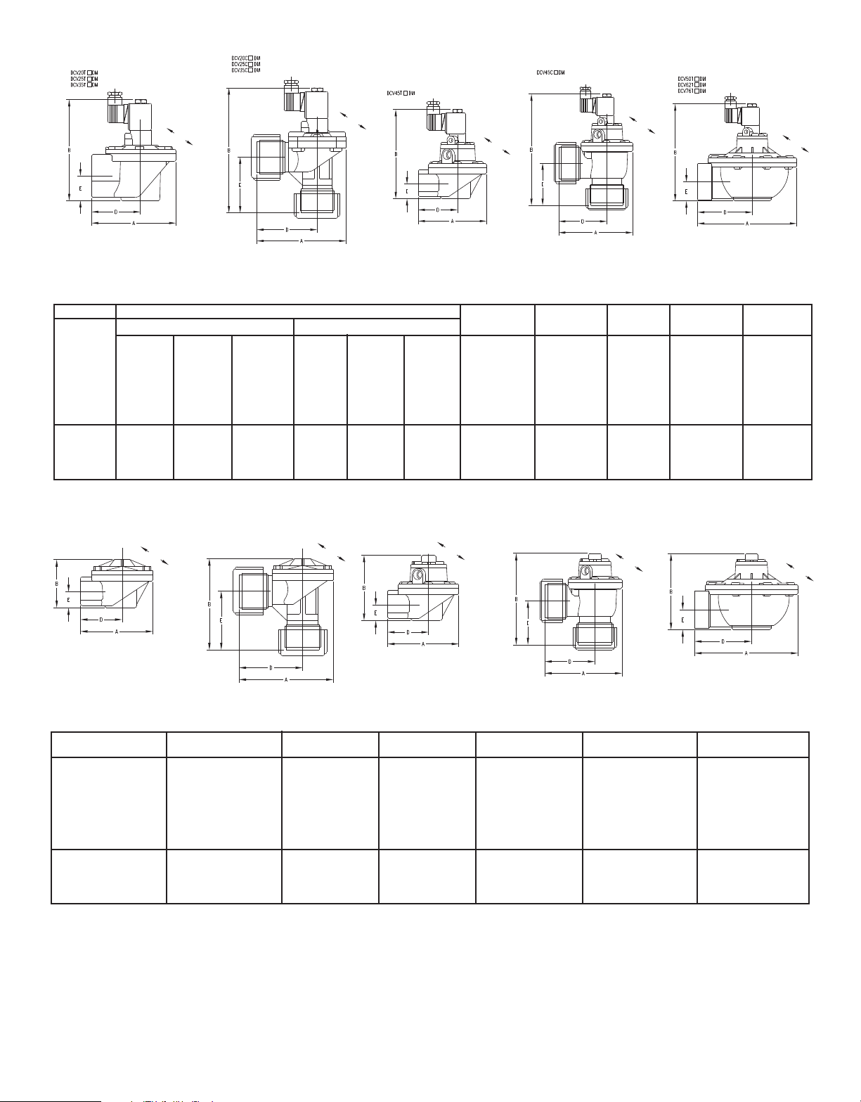
DCV DIMENSIONAL CHART
C WIDTH
C WIDTH
C WIDTH
C WIDTH
C WIDTH
Connection
DIN Electrical Connection
DCV20T2D
DCV25T2D
DCV35T2D
DCV45T2D
DCV50T2D
DCV62T2D
DCV76T2D
DCV20C2D
DCV25C2D
DCV35C2D
DCV45C2D
NPT
Coupling
DCV20T1D
DCV25T1D
DCV35T1D
DCV45T1D
DCV50T1D
DCV62T1D
DCV76T1D
DCV20C1D
DCV25C1D
DCV35C1D
DCV45C1D
Model Number
DCV20T3D
DCV25T3D
DCV35T3D
DCV45T3D
DCV50T3D
DCV62T3D
DCV76T3D
DCV20C3D
DCV25C3D
DCV35C3D
DCV45C3D
Lead Wires Electrical Connection
DCV20T1L
DCV25T1L
DCV35T1L
DCV45T1L
DCV50T1L
DCV62T1L
DCV76T1L
DCV20C1L
DCV25C1L
DCV35C1L
DCV45C1L
DCV20T2L
DCV25T2L
DCV35T2L
DCV45T2L
DCV50T2L
DCV62T2L
DCV76T2L
DCV20C2L
DCV25C2L
DCV35C2L
DCV45C2L
DCV20T3L
DCV25T3L
DCV35T3L
DCV45T3L
DCV50T3L
DCV62T3L
DCV76T3L
DCV20C3L
DCV25C3L
DCV35C3L
DCV45C3L
A (A mm)
3-15/16˝ (100)
4-1/8˝ (105)
5-1/8˝ (130)
5-1/8˝ (130)
8-1/16˝ (205)
8-9/32˝ (210)
8-19/32˝ (218)
4-13/32˝ (112)
4-5/8˝ (117)
5-13/16˝ (147)
5-25/32˝ (147)
B (B mm)
4-13/16˝ (122)
4-31/32˝ (126)
6-1/16 (154)
7-7/32˝ (183)
7-29/32 (201)
8-3/4˝ (222)
9-7/8˝ (251)
5-27/32˝ (148)
6-21/32˝ (177)
7-21/32˝ (194)
8-27/32˝ (224)
C (C mm)
3-7/16˝ (87)
3-1/4˝ (83)
4-3/8˝ (111)
4-3/8˝ (111)
7-1/4˝ (184)
7-1/4˝ (184)
7-7/8˝ (200)
3-7/16˝ (87)
3-1/4˝ (83)
4-3/8˝ (111)
4-3/8˝ (111)
D (D mm)
2-3/16˝ (56)
2-1/2˝ (64)
4-1/2˝ (114)
4-1/2˝ (114)
4-15/32˝ (113)
4-21/32˝ (118)
4-21/32˝ (118)
2-5/8˝ (67)
3˝ (76)
3-5/8˝ (91)
3-5/8˝ (91)
E (E mm)
25/32˝ (20)
7/8˝ (22)
1-9/32˝ (33)
1-9/32˝ (33)
1-9/16˝ (40)
1-29/32˝ (48)
2-1/2˝ (63)
1-25/32˝ (45)
2-3/4˝ (70)
3˝ (76)
3˝ (76)
RDCV DIMENSIONAL CHART
Connection
NPT
Coupling
Model
Number
RDCV20T
RDCV25T
RDCV35T
RDCV45T
RDCV50T
RDCV62T
RDCV76T
RDCV20C
RDCV25C
RDCV35C
RDCV45C
A (A mm)
3-15/16˝ (100)
4-1/8˝ (105)
5-1/8˝ (130)
5-25/32˝ (147)
8-1/16˝ (205)
8-9/32˝ (210)
8-19/32˝ (218)
4-13/32˝ (112)
4-5/8˝ (117)
5-13/16˝ (147)
5-25/32˝ (147)
B (B mm)
2-31/32˝ (75)
3˝ (76)
4-29/32˝ (125)
5-5/32˝ (131)
5-7/8˝ (149)
6-11/16˝ (170)
7-27/32˝ (199)
4˝ (102)
5˝ (127)
5-15/32˝ (139)
6-25/32˝ (172)
C (C mm)
3-7/16˝ (87)
3-1/4˝ (83)
4-3/8˝ (111)
4-3/8˝ (111)
7-1/4˝ (184)
7-1/4˝ (184)
7-7/8˝ (200)
3-7/16˝ (87)
3-1/4˝ (83)
4-3/8˝ (111)
4-3/8˝ (111)
D (D mm)
2-3/16˝ (56)
2-1/2˝ (64)
4-1/2˝ (114)
3-5/8˝ (91)
4-15/32˝ (113)
4-21/32˝ (118)
4-21/32˝ (118)
2-5/8˝ (67)
3˝ (76)
3-5/8˝ (91)
3-5/8˝ (91)
E (E mm)
25/32˝ (20)
7/8˝ (22)
1-9/32˝ (33)
3˝ (76)
1-9/16˝ (40)
1-29/32˝ (48)
2-1/2˝ (63)
1-25/32˝ (45)
2-3/4˝ (70)
3˝ (76)
3˝ (76)
Page 3

OPERATION
Series DCV includes an integral solenoid and Series RDCV needs to be
used with a remote pilot solenoid valve. Both are normally closed valves.
When the remote pilot solenoid valve or integral solenoid opens, pressure is released (exhausted) from the top of the diaphragm in the pulse
valve. This allows the line pressure on the bottom of the diaphragm to
push the diaphragm up and open the main orifice of the pulse valve.
When the solenoid then closes the pressure on the bottom and the top
of the diaphragm equalize closing the main orifice of the pulse valve.
INSTALLATION
Warning: Before installation make sure all air pressure has
been released, electric power has been turned off, and air pressure source has been closed. Turn power on and increase pressure only after installation is complete.
LOCATION
Select a location that will not exceed the ambient temperature specifications of the valve. The system must be located in an enclosure that
meets relevant safety standards and electrical codes of the environment.
MOUNTING
The DCV/RDCV can be mounted in any position. For optimum life and
performance it is recommended that the unit be mounted vertically and
upright to reduce the chance of foreign matter accumulating in the valve.
For DCV in weatherproof applications it is recommended that the cable
gland be positioned face down to avoid possible rainfall or water from
entry.
Wiring Connections
(For DCV units)
Wire in accordance with the National Electrical Code and local regulations. To aid in wiring the solenoid on the DCV may be rotated 360°. It is
recommended to use 18 AWG copper wire rated at 90°C or greater.
Wiring the DCV with DIN connector. See Figure 1.
1. Remove center screw and pull wiring assembly from the body.
2. Remove gasket and place small screwdriver in slot to pry out the terminal block from the cover.
3. Thread wire through the gland nut, gland gasket, washer and connector cover.
4. Connect wires to proper terminals on the terminal block.
5. Snap terminal block back into the cover. The connector cover may be
rotated in 90° increments to position the cable entry as needed for the application. Reinstall the center screw and screw back into the solenoid
body.
MAINTENANCE
Warning: To prevent the possibility of death, serious injury or property
damage, turn off electrical power, depressurize system and unit, and vent
fluid to a safe area before servicing.
The DCV/RDCV should be cleaned periodically. The amount of time between cleanings depends on the application. Preventive Maintenance includes keeping media clean of material and oil free, and periodic testing
to ensure proper operation and to look for wear or damage. Replacement
diaphragm assemblies are available from the factory.
PROCESS CONNECTIONS
For DCV/RDCV with coupling connections:
1. Connect piping so that pneumatic input is the bottom connection and
the outlet is the side connection at 90°.
2. Stub pipe (blow tube) must be free of burrs, rust, oil, and other debris.
3. Disassemble compression fittings and place the retaining nut, retainer, and gasket onto the piping. Make sure that the beveled edge of the
gasket faces the valve body.
4. Connect fittings to the valve body. Make sure that the pipe is inline with
the valve ports. Nut and seals are for connection only and should not be
used for support purposes.
Notes:
• Make sure pipes are anchored securely to avoid separation from the
valve.
• Do not use the valve for leverage when connecting piping.
• Do not over-tighten retaining nut or valve damage may result. Tighten
retaining nuts just sufficiently for sealing to prevent leakage. This is a
gasket seal and does not require excessive turning of the nut.
For DCV/RDCV with NPT connections:
1. Connect piping so that pneumatic input is the bottom connection and
the outlet is the side connection at 90°.
2. Stub pipe (blow tube) must be free of burrs, rust, oil, and other debris.
3. Thread piping into the valve body. Make sure that the pipe is inline with
the valve ports. If using tape or pipe compound, apply to the male piping
threads and use sparingly as it may come loose and affect valve operation. Do not apply tape or pipe compound directly to the female valve
body threads.
Figure 1
Notes:
• Make sure pipes are anchored securely.
• Do not use the valve for leverage when connecting piping.
Pressure Connection from Remote Pilot Solenoid Valve
(For RDCV units)
The RSV, remote pilot solenoid valve, should be mounted as close as
possible to the RDCV pulse valve. The maximum distance is 9.8 ft (3 m).
Tubing from the remote solenoid valve is connected to the exhaust port
on the top of the RDCV pulse valve. If using tape or pipe compound,
apply to the male piping threads and use sparingly as it may come loose
and affect valve operation. Do not apply tape or pipe compound directly
to the female valve body threads.
Page 4

Solenoid Valve Troubleshooting
Problem
No pulse
Leakage in outlet port
Low pulse
Shaking noise
Solenoid noise
Possible Cause
No supply air
Air pressure is too high
No voltage to RSV
Solenoid is damaged
Improper installation of inlet port
Low air pressure
Valve screws are loose
Solenoid mounting screws are loose
Action Required
Check whether the air compressor and valve have been turned on
Check the pressure of the air supply
Check supply voltage
Send back for evaluation
Check the pipe connections between the inlet and outlet
Check air supply pressure
Verify that the air supply was distributed properly
Tighten the loose screws
Tighten the loose screws
WARRANTY
The Series DCV/RDCV is not field serviceable and should be returned if
repair is needed (field repair should not be attempted an may void warranty). Be sure to include a brief description of the problem plus any relevant application notes. Contact customer service to receive a return
goods authorization number before shipping.
©Copyright 2010 Dwyer Instruments, Inc. Printed in U.S.A. 2/10 FR# R2-443335-01 Rev. 1
DWYER INSTRUMENTS, INC.
Phone: 219/879-8000 www.dwyer-inst.com
P.O. BOX 373 • MICHIGAN CITY, INDIANA 46361, U.S.A. Fax: 219/872-9057 e-mail: info@dwyer-inst.com
 Loading...