

Page 1
Instruction Manual
PORTABLE TYPE
ULTRASONIC FLOWMETER
TYPE: CONVERTER PUX
DETECTOR PSX2
Dwyer Instruments, Inc.
Bulletin F-68
Page 2

BULLETIN F-68
PREFACE
You are now a proud owner of Dwyer Instruments ultrasonic flowmeter (Model PUX).
This manual explains cautions in use, wiring, operation, installation, troubleshooting, maintenance, and options
of the portable type ultrasonic flowmeter. Please read through the manual before using the instrument.
Keep this manual in a convenient location for future reference.
Manufacturer : Dwyer Instruments, Inc.
Type : Described on nameplate on main frame
Date of manufacture : Described on nameplate on main frame
Product nationality : Japan
Request
• Copy of contents of this manual in part or whole is not authorized
without permission.
• Contents of the manual are subject to change without prior notice.
© Dwyer Instruments, Inc.
Issued in June 2007
i
Page 3

CONTENTS
BULLETIN F-68
1. OVERVIEW.......................................................................................................................1 - 1
2. CHECK OF DELIVERED ITEMS ...................................................................................2 - 1
2.1 On purchase of converter .........................................................................................2 - 1
2.2 On purchase of detector ...........................................................................................2 - 2
3. NAME AND EXPLANATION OF EACH PART................................................................3 - 1
3.1 Name and explanation of main unit and sensor........................................................3 - 1
3.2 Explanation of keys ..................................................................................................3 - 2
4. POWER UP ..........................................................................................................................4 - 1
4.1 Operating power supply............................................................................................ 4 - 1
4.2 Turning on power supply..........................................................................................4 - 2
5. WIRING ............................................................................................................................... 5 - 1
5.1 Connection of dedicated cables ................................................................................5 - 1
5.2 Connection of analog input/output cable..................................................................5 - 1
5.3 Connection of RS-232C cable ..................................................................................5 - 2
6. INPUT OF PIPING SPECIFICATIONS ...........................................................................6 - 1
6.1 Display of pipe setup screen.....................................................................................6 - 1
6.2 Entry of site name (measurement is possible without entry).................................... 6 - 3
6.3 Outer diameter of piping (unit: mm) (range: 13 to 6000 mm) .................................6 - 4
6.4 Piping material..........................................................................................................6 - 5
6.5 Wall thickness (unit: mm).........................................................................................6 - 6
6.6 Lining material ......................................................................................................... 6 - 7
6.7 Lining thickness (unit: mm) (range: 0.01 to 100.00 mm) ........................................ 6 - 8
6.8 Kind of fluid .............................................................................................................6 - 9
6.9 Selection of sensor mounting method .................................................................... 6 - 10
6.10 Kind of sensor.........................................................................................................6 - 11
6.11 Transmission voltage (used when an indicator is 1 or less during
measurement)..........................................................................................................6 - 12
7. MOUNTING OF DETECTOR ............................................................................................7 - 1
7.1 Selection of mounting location.................................................................................7 - 1
7.2 Selection of mounting method..................................................................................7 - 3
7.3 Treatment of detector mounting face........................................................................7 - 4
7.4 How to mount small size (standard) sensor and small outer diameter
7.5 How to mount large size sensor................................................................................7 - 6
ii
sensor to pipe ............................................................................................................7 - 5
7.5.1 How to determine mounting position (large sensor) ................................................ 7 - 6
7.5.2 How to connect large size sensor.............................................................................. 7 - 7
7.5.3 How to mount large size sensor to pipe.................................................................... 7 - 8
Page 4

7.6 How to mount high temperature sensor to pipe........................................................7 - 9
BULLETIN F-68
7.7 How to mount medium diameter sensor to pipe.....................................................7 - 10
7.8 How to fold gauge paper (used for determining mounting position) .....................7 - 10
8. MEASUREMENT .............................................................................................................8 - 1
9. SETTING OPERATION (APPLICATION) ......................................................................9 - 1
9.1 How to use SITE SETUP function (SITE SETUP page) ......................................... 9 - 2
9.1.1 PARAMETER MEMORY: when registering data which are set and
calibrated on the page .............................................................................................. 9 - 2
9.1.2 ZERO ADJUST: when performing zero adjustment............................................... 9 - 3
9.1.3 RESPONSE SET: when changing output response.................................................9 - 3
9.1.4 OUTPUT CORRECTION: when calibrating measured value
(output calibration function) ..................................................................................... 9 - 4
9.1.5 CUT OFF: output cut off at low flow rate (low flow cutoff function) ..................... 9 - 5
9.1.6 TOTALIZE: when performing the integration process of measured data
(totalize)................................................................................................. 9 - 6
9.2 Setting of logging function (data logger page).........................................................9 - 7
(1) SETUP: when setting logging of measured data....................................................... 9 - 8
(2) GRAPH: when checking logged data on screen ...................................................... 9 - 11
(3) PRINT: when printing logged data in text ...............................................................9 - 13
(4) DELETE: when deleting logged data ......................................................................9 - 14
(5) START: when starting logging
[logging starts by conditions set in (1), “SETUP”] .................................................9 - 14
9.3 Setting of system (page title: SYSTEM SETUP)...................................................9 - 15
9.3.1 CLOCK SET: when setting the clock (set the present time) ................................. 9 - 15
9.3.2 COMMUNICATION: when setting serial communication
(data communication to personal computer) .......................................................... 9 - 15
9.3.3 SYSTEM OF UNITS: when setting the measurement and setting
unit system [selection of meter system and inch system]....................................... 9 - 16
9.3.4 MEASUREMENT METHOD: when changing measurement method .................. 9 - 17
9.3.5 MEMORY INITIALIZE: all setting parameters and logger data are initialized. ... 9 - 17
9.4 Setting of analog input/output (analog page) .........................................................9 - 18
9.4.1 Setting of analog input............................................................................................ 9 - 18
9.4.2 Setting of analog output.......................................................................................... 9 - 20
9.5 Use of printer function (printer page).....................................................................9 - 23
9.5.1 Selection of mode ................................................................................................... 9 - 23
9.5.2 Selection of items to print....................................................................................... 9 - 24
9.5.3 Setting of print time ................................................................................................ 9 - 27
9.5.4 To set printing intervals .......................................................................................... 9 - 31
9.5.5 To set graph scale in graph mode ...........................................................................9 - 31
9.5.6 Printing ...................................................................................................................9 - 32
9.5.7 Printing stop............................................................................................................ 9 - 32
iii
Page 5

9.6 System check function (system check page) ..........................................................9 - 33
BULLETIN F-68
9.6.1 ERROR CHECK .................................................................................................... 9 - 33
9.6.2 SIGNAL CHECK ................................................................................................... 9 - 35
9.6.3 OUTPUT CHECK .................................................................................................. 9 - 38
9.6.4 VERSION NO. ....................................................................................................... 9 - 38
10. MAINTENANCE AND CHECKUP................................................................................ 10 - 1
11. ERROR AND HANDLING .............................................................................................11 - 1
11.1 Error in LCD display .............................................................................................. 11 - 1
11.2 Error of key.............................................................................................................11 - 1
11.3 Error in measured value..........................................................................................11 - 2
11.4 Error in analog output.............................................................................................11 - 5
11.5 Display of error.......................................................................................................11 - 5
12. SPECIFICATIONS FOR SERIAL TRANSMISSION (RS-232C) ..................................12 - 1
13. HOW TO USE PRINTER ................................................................................................13 - 1
13.1 How to connect printer ...........................................................................................13 - 1
13.2 How to load printer roll sheet .................................................................................13 - 2
14. REPLACEMENT OF BUILT-IN BATTERY...................................................................14 - 1
15. APPENDIX.......................................................................................................................15 - 1
15.1 Piping data .............................................................................................................. 15 - 1
15.2 Command tree ........................................................................................................15 - 7
15.3 Specifications..........................................................................................................15 - 8
15.4 Q & A ...................................................................................................................15 - 10
iv
Page 6
WARNING SYMBOLS AND THEIR MEANINGS
BULLETIN F-68
Be sure to observe the following precautions. They offer important information on safety.
• The degree of injuries or damages resulting from improper handling of this device is indicated
by different symbols.
Symbol
Improper handling of this device may cause dangerous
CAUTION
• The following symbols describe items to be observed.
Symbol
The symbol indicates “prohibition”.
Meaning
situations that result in personal injury or property
damage.
Symbol
Meaning
Meaning
Do not modify this device.
The symbol indicates “mandatory” action to be taken.
The symbol provokes “cautions”.
Be sure to pull out the plug.
Be careful. It may result in fire.
v
Page 7
SAFETY PRECAUTIONS
BULLETIN F-68
Be sure to read this “Safety Precautions” carefully beforehand for the correct and safe use of this
device.
WARNING
Do not touch the switch
Do not break or pull the power cord.
with a wet hand.
Do not touch the switch with a
wet hand. Otherwise it may
result in electric shock.
Prohibition Prohibition
Do not modify.
Do not modify this device.
Otherwise it may result in an
accident.
Modification
is prohibited.
Do not use electric parts soaked
Prohibition
Pull out the plug immediately
Do not repair.
in case of an emergency
Do not put heavy things on the
power cord. Do not modify or
pull the power cord.
Otherwise it may break and
result in electric shock and fire.
in water
Replace electric parts or wires
soaked in water due to floods or
some other reasons with new
ones. Otherwise it may result in
electric shock or fire.
Repair should be made only by
authorized servicepersons. Ask
your dealer for the repair.
Improper repair work may result
in electric shock, fire, or injury.
Pull out
the plug
In case abnormal odor, smoke or
fire is perceived, pull the power
plug immediately. Ask an
authorized serviceperson or your
dealer for repair.
Otherwise it may result in electric
shock or fire.
vi
Page 8
CAUTION
BULLETIN F-68
Keep warning labels clean.
Clean or replace the warning
labels so that they can always be
read correctly.
Otherwise it may result in an
accident.
Ask an authorized waste disposal
specialist for disposal.
Do not dispose the device
without proper authorization.
Otherwise it may cause
environmental pollution or result
in an accident.
Do not splash water.
Inspect the power plug periodically.
Inspect the power plug once
every 6 months. Wipe the dust
off the plug and insert it securely.
Otherwise it may result in electric
shock or fire.
Match power capacity
with the device ratings.
Be sure to connect the device to
the power with sufficient
allowable voltage and current.
Fire hazard
Otherwise it may result in fire.
Use an exclusive power adapter
and built-in battery
Do not wash or splash water on
the electrical parts inside the
device.
Prohibition
Otherwise it may result in electric
shock.
Be careful when carrying the device
When carrying the device,
exercise care to avoid physical
shock or vibration.
Otherwise it may cause failure.
Prohibition
favorable environment.
Do not use a power adapter or
built-in battery that is not
exclusive to the main unit.
Otherwise it may break and
cause failure.
Use the device in
Do not use the device in an
environment subjected to dust
or corrosive gases.
Otherwise it may cause failure.
vii
Page 9

1. OVERVIEW
BULLETIN F-68
This is a portable type ultrasonic flowmeter that allows easy measurement of flow rates in pipes
by installing a sensor on the outside of pipes.
A combination of the latest electronics and digital signal process technologies makes this instrument compact,
designed for improvement of performance and easy operation.
1 - 1
Page 10
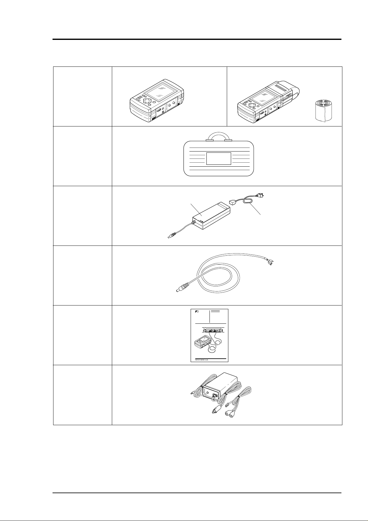
2. CHECK OF DELIVERED ITEMS
BULLETIN F-68
2.1 On purchase of converter (type: PUX)
Without printer With printer
Conversion unit
Carrying case
DWYER INSTRUMENTS, INC.
D
E
E
N
F
O
F
F
O
Roll paper
AC power supply
adapter
Power cord
Analog input/output
cord
Instruction manual
(BULLETIN F-68)
()
AC power supply adapter
Dwyer Instruments, Inc.
Instruction Manual
PORTABLE TYPE
ULTRASONIC FLOWMETER
TYPE: CONVERTERPUX
DETECTOR
PSX2
Power cord
Bulletin F-68
(option)
DC power supply
adapter
D
C
O
U
T
P
U
T
D
C
I
N
P
U
T
2 - 1
Page 11
2.2 On purchase of detector (type: PSX2)
BULLETIN F-68
The following parts will be delivered.
So, make sure all the parts are delivered.
(1) Main unit
Large type (2pcs)
(Type: PSX2 D)
Middle type (2pcs)
(Type: PSX2 C)
(2) Accessories
• Fastening spring
• φ 2mm wire rope
• Plastic cloth belt
• Stainless steel beld
• Silicone grease
•
Grease for high temperature
• Cable for exclusive use
(BNC at both ends)
Large
type
Small type (standard)
(Type: PSX2 A & E)
Medium
type
Small
type
Small
diameter
Small diameter
(Type: PSX2 B)
High
tempe-
Quantity Remarks
rature
2 pcs
2 pcs
1 pc
4 pcs
(long)
2 pcs
(short)
1 pc
1 pc
2 pcs
High-temperature
(Type: PSX2 HT)
Maker: Shinetsu
Type:
Chemical Industry
G40M (100g)
Maker: Shinetsu
Chemical Industry
Type:
KS62M (100g)
• Cable for exclusive use
(BNC at one end)
2 - 2
2 pcs
Note) Supplied for
PSX2 D only
Page 12
3. NAME AND EXPLANATION OF EACH PART
BULLETIN F-68
3.1 Name and explanation of main unit and sensor
Fluid
ON OFF
LIGHT
PRINT
FAST CHARGE
Printer
Detector
Cable for exclusive use
Display
window
ENT
DC IN
ESC
Keyboard
• Keyboard : Used for turning on/off power supply of the main unit, outputting a hard copy with
the printer, inputting fluid specifications and setting the function of the meter.
• Display window : Displays measured value. Also used for display in data input or setting by keys.
Because this is a large-size graphic LCD, indications are easier to read. Even at a
dark place, indications can be read by using the backlight.
• Printer (option) : Capable of printing all information possessed by the PUX including the hard copy of
display screen and printout of measured value.
Meter comprises a logger function (for storing measured values in memory).
After storing a few day's data in memory by the logger function, it can be printed.
• Detector : Attached to a pipe and receives/transmits ultrasonic wave.
• Cable for exclusive use: Used for transmitting to the instrument signals into which flow rates measured
by the detector have been converted.
3 - 1
Page 13
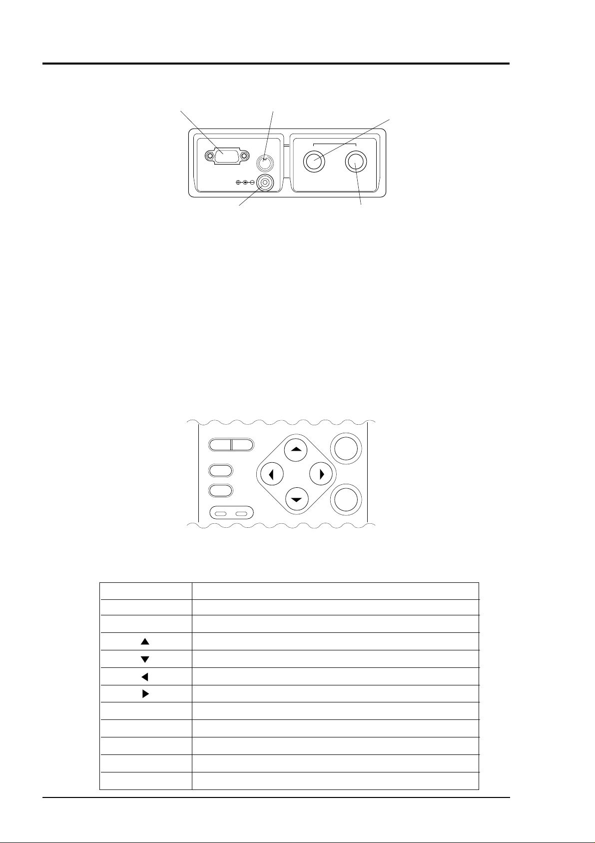
SERIAL
BULLETIN F-68
(RS-232C connector for
personal computer)
SERIAL
ANALOG IN/OUT
(4 to 20mA DC analog I/O connector)
SENSOR
DC17.5V
ANALOG
IN/OUT
UPSTREAM
(Detector connector on
upstream side)
STREAMDOWNSTREAMUP
17.5 V DC (power connector)
• Connectors : 17.5V DC
Connector of main unit power supply. Inputs 17.5V DC.
Insert the plug of the power adapter tailored for this instrument.
: UP STREAM (upstream side), DOWN STREAM (downstream side)
These are connectors which receive sensor cords.
Connect matching the upstream and downstream sides.
: ANALOG IN/OUT
Connect analog input/output signals (4 to 20mA DC).
: SERIAL
Connector for serial transmission. Connect to an external system such as personal
computer.
3.2 Explanation of keys
Fig. 3-1 shows the layout of keys and Table 3-1 explains each key.
ON OFF
LIGHT
PRINT
FAST CHARGE
DOWNSTREAM (Detector connector on downstream side)
Connectors
ENT
ESC
DC IN
3 - 2
Fig. 3-1 Layout of keys
Table 3-1 Explanation of keys
Key indication lamp Description
ENT The keyed-in data, selected item, etc. will be set by pressing this key.
ESC Cancels any setting.
Moves the cursor upward, increments set value, etc.
Moves the cursor downward, decrements set value, etc.
Moves the cursor leftward, change scale, etc.
Moves the cursor rightward, change scale, etc.
ON/OFF Turns on/off power supply.
PRINT Prints the screen display (outputs a hard copy).
LIGHT Turns on/off the backlight of display screen.
FAST CHARGE
Turns ON in charge. Blinks in fully charged condition.
DC IN Turns ON with power cable connected.
Page 14
4. POWER UP
BULLETIN F-68
4.1 Operating power supply
There are two methods available for energizing this instrument; by the built-in battery or with
the power adapter.
(1) Energizing with built-in battery
q To charge the battery
Turn OFF the instrument power and
connect the AC power adapter. The
“FAST CHARGE” LED is lighted in
red, and “DC IN” LED is lighted in
green.
When the instrument is fully charged,
“FAST CHARGE” LED blinks in red.
* About 2 hours will be required for
charging.
* In the fully charged condition, the
instrument can measure for about 5
hours.
(On condition that the display backlight
is turned off and the printer is unused.)
w To energize by built-in battery
When turning on the power supply without connecting the power adapter, the instrument will
be energized by the built-in battery.
Before use, the battery should be fully charged.
FAST CHARGE
DC IN
ON OFF
LIGHT
PRINT
FAST CHARGE
ENT
DC IN
ESC
(2) Energizing by power adapter
CAUTION
Use the exclusive power adapter only. Don’t use other adapters, or it may result in an
accident.
• AC power adapter
q Connect the output plug of AC power
adapter to the 17.5V DC connector of
main unit.
w Insert the input plug of this adapter into
the power receptacle.
(This adapter has an input voltage range
of 90 to 264V AC (at 50/60Hz).)
• DC power adapter
q Connect the output plug of DC power
adapter to the 17.5V DC connector of
main unit.
w Connect the input wires (+ and -) of DC
power adapter to suitable DC power
supply.
SERIAL
SERIAL
DC17.5V
DC17.5V
ANALOG
IN/OUT
ANALOG
IN/OUT
SENSOR
SENSOR
STREAMDOWNSTREAMUP
STREAMDOWNSTREAMUP
(This adapter has an input voltage range
of 10 to 30V DC.)
4 - 1
Page 15
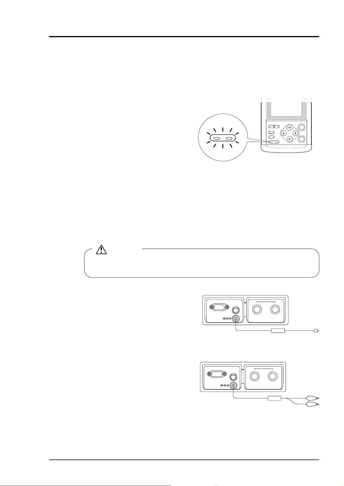
4.2 Turning on power supply
BULLETIN F-68
q Press the ON switch of the main unit to turn ON the power.
w Turn ON the power, and the following
screen appears.
DWYER INSTRUMENTS, INC.
English
ESC
Language to be set is
displayed.
To select the language
When the language display is
highlighted (for about 5 sec.), press
the ESC key, and the “LANGUAGE
SELECTION” screen appears.
In the screen that is displayed, select
your desired language and press the
ENT key. It returns to the
“MEASUREMENT” screen.
e If there is nothing you can do on the
screen for about 10 sec. the
“MEASURE” screen appears.
Select language
Wahle Sprache
Cholx de la langue
ENT
English/ /English/ANGLAIS
Japanese/ /Japanisch/JAPONAIS
German/ /Deutsch/ALLEMAND
French/ /Franzosisch/FRANCAIS
Note:
From the next step, the
language you selected can
be used.
95-06-27 11:49
FLOW RATE UNIT: m3/h
x10
VELOCITY UNIT: m/s
MEASURE
x10
+ TOTAL UNIT: ml
STOP
RESET
— TOTAL UNIT: ml
STOP
RESET
ENT
4 - 2
Note1) Select any of 4 languages: English, French, German, and Japanese (Katakana)
Note2) To return to the “LANGUAGE SELECTION” screen from the “MEASUREMENT” screen
in display, turn OFF the power once and then turn it ON again. In the initial screen that is
displayed, press the
ESC
key.
Page 16
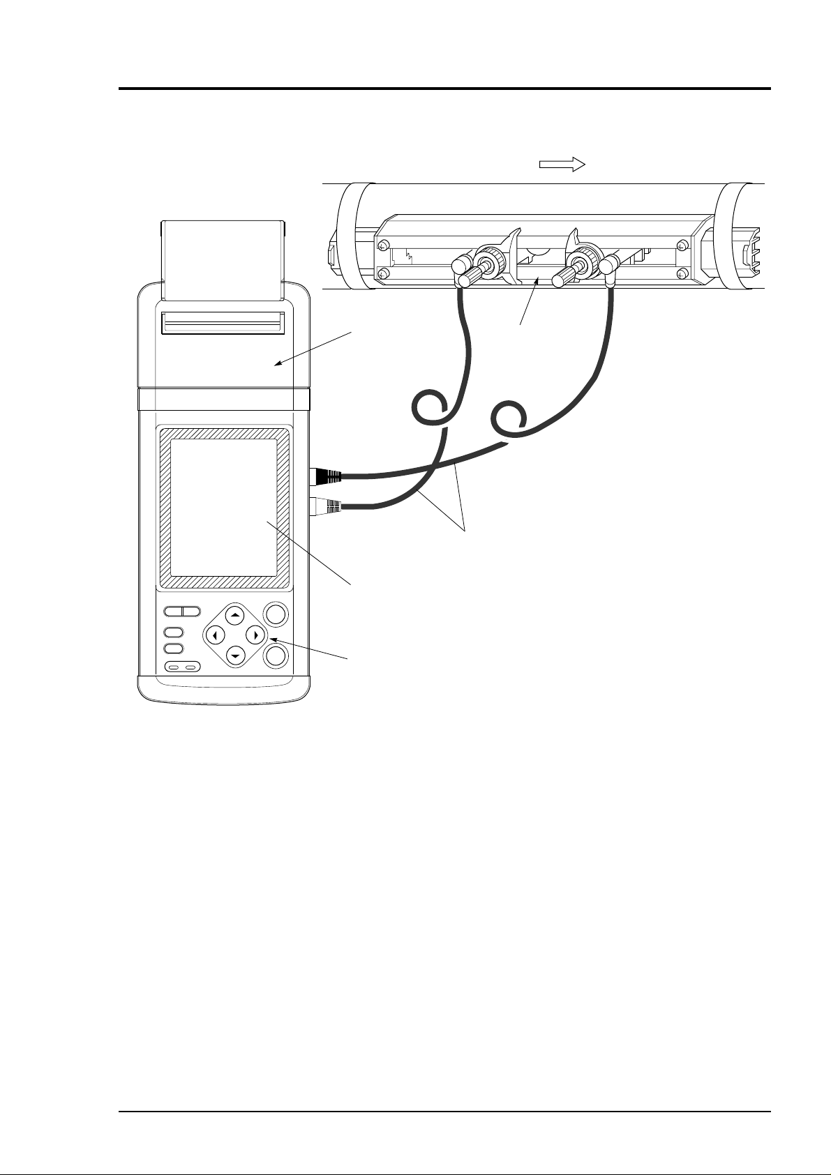
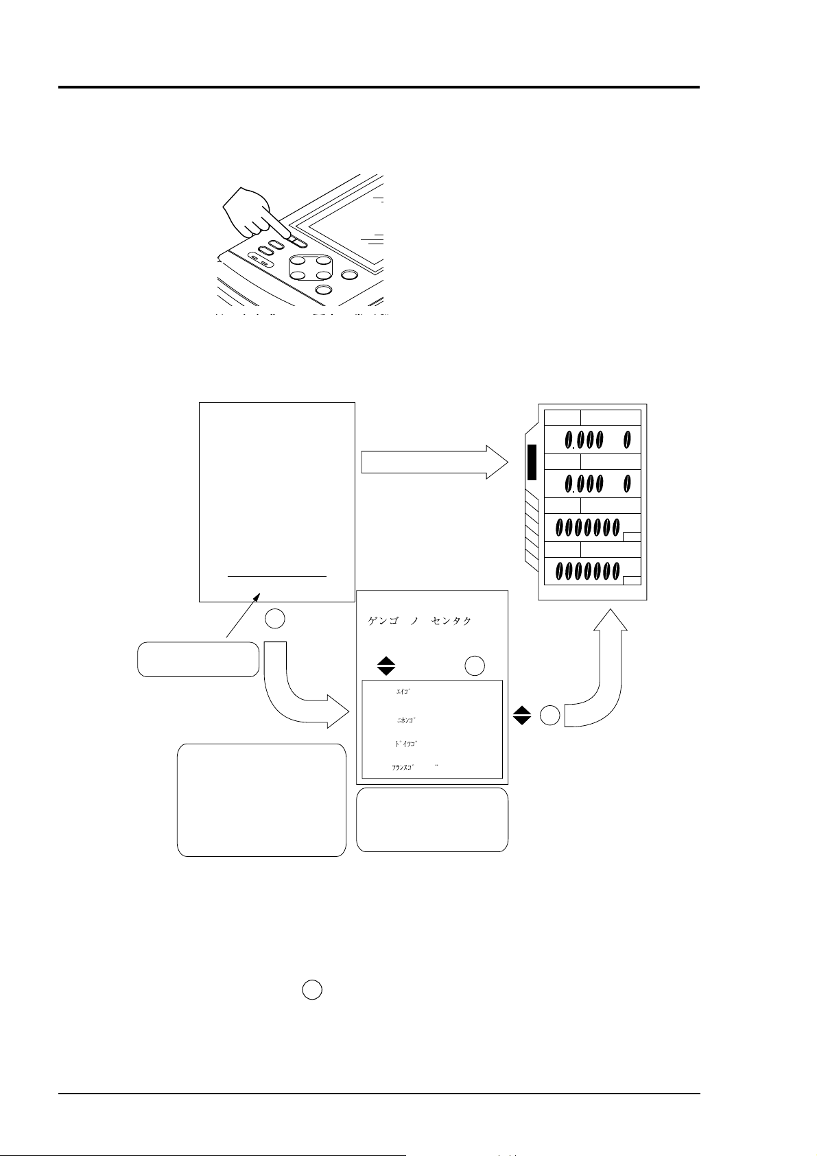
5. WIRING
BULLETIN F-68
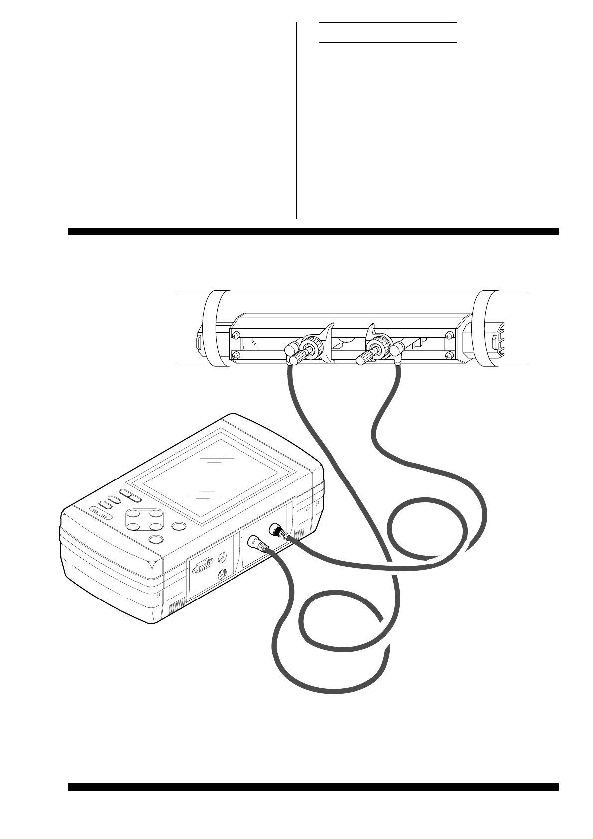
5.1 Connection of dedicated cables
This cable is used for connecting the detector to the main unit.
q Connect dedicated cables to the upstream and downstream sides of the detector.
w Connect one cable connected to the upstream side of the detector to the “UP STREAM” connector of
the main unit, and connect the other cable connected to the down stream side of the detector to the
“DOWN STREAM” connector.
SERIAL
DC17.5V
ANALOG
IN/OUT
SENSOR
STREAMDOWNSTREAMUP
Upstream Downstream
Flow direction
5.2 Connection of analog input/output cable (4 to 20 mA DC)
This cable is used for connection of receiving instruments (indicators, recorders, etc.) and the main unit.
Analog I/O cable is connected as shown below. The cable end is treated with a clip.
Red (+)
AO
(output)
Black (-)
Detector
4 to 20mA
Note) Plug the connector
into ANALOG
IN/OUT.
AI
(input)
Red (+)
Black (-)
-
+
Indicator,
recorder,
controller, etc.
q Connect clips of the analog I/O cable to the (+) and (-) sides of the receiving instruments, respectively.
w Connect the analog I/O cable to the “ANALOG IN/OUT” connector at the side panel of the main unit.
Note) Allowable load resistance of analog output should be adjusted to 1 kΩ or less.
Input resistance of analog input is 100Ω.
Converter
AO
AI
Red
Black
Red
Black
+
A
-
5 - 1
Page 17
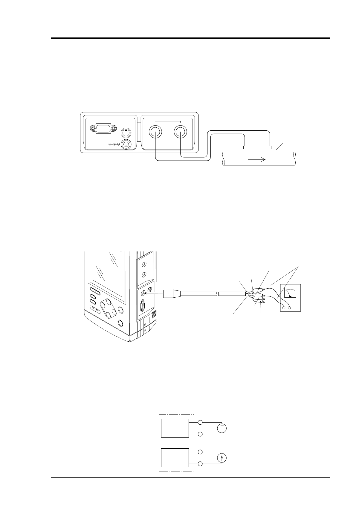
5.3 Connection of RS-232C cable
BULLETIN F-68
When using an optional personal computer, use RS-232C cable for serial transmission between
the RS-232C connector of the personal computer and the “SERIAL” connector of the main unit.
For PC software, refer to Chapter 12.
SERIAL
DC17.5V
ANALOG
IN/OUT
SENSOR
STREAMUP
RS-232C
STREAMDOWN
5 - 2
Page 18
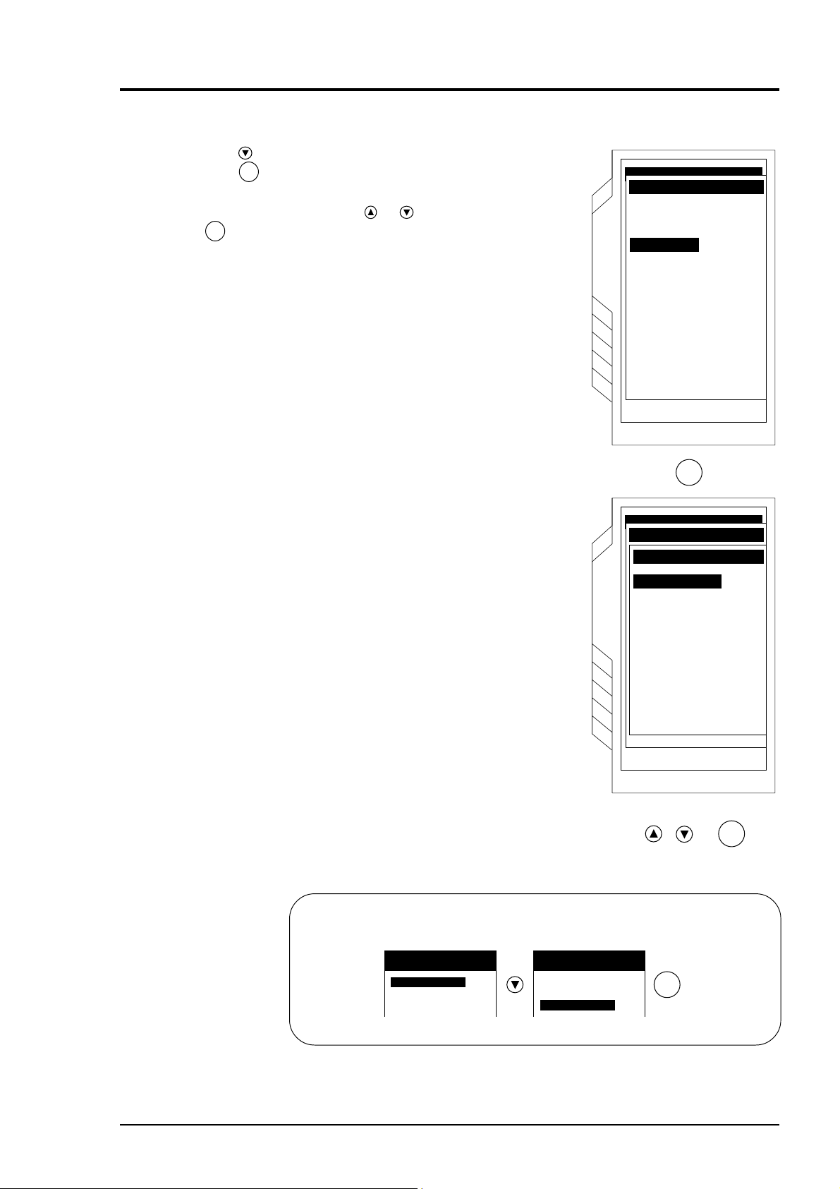
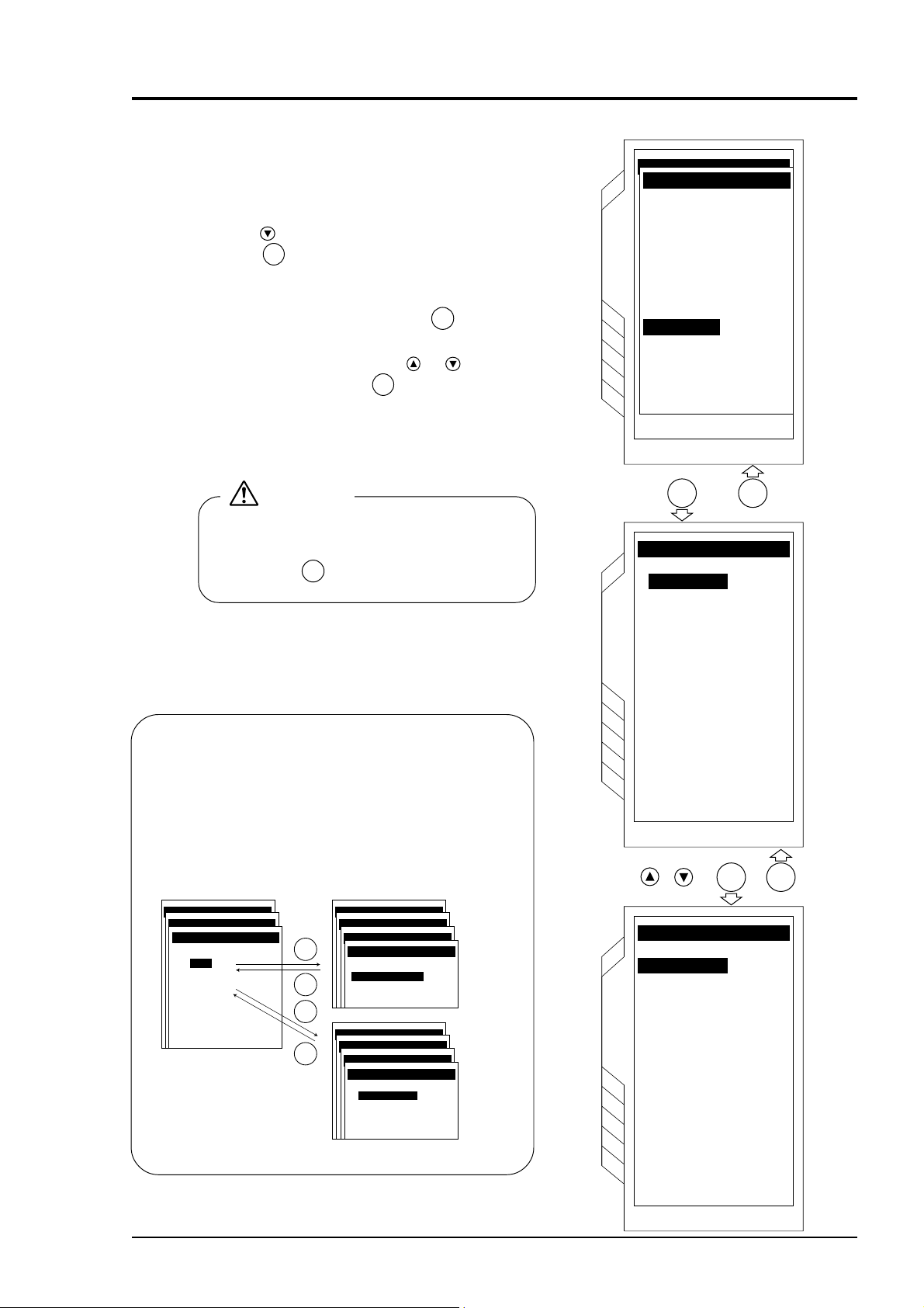
6. INPUT OF PIPING SPECIFICATIONS
BULLETIN F-68
Before installing the detector, set the specifications of a pipe in the main unit to allow measurements.
Caution) Measurements cannot be accomplished without these settings.
95-06-27 11:49
6.1 Display of pipe setup screen
q Press the
to invert the “Tab”.
w Press the
menu screen is displayed.
To move the cursor on the screen, press the
key or
To invert “PIPE PARAMETER” on the menu
screen , press the
SETUP” screen.
key on the “MEASURE” screen
key, and the “SITE SETUP”
ENT
key.
key on the “SITE
Title of page
Invert the
PIPE
PARAMETER
FLOW RATE UNIT: m3/h
x10
VELOCITY UNIT: m/s
MEASURE
x10
+ TOTAL UNIT: ml
– TOTAL UNIT: ml
95-06-27 14:49
SITE SETUPSITE SETUP
PARAMETER MEMORY
PIPE PARAMETER
ZERO ADJUST
RESPONSE SET
SITE SETUP
CALIBRATION
CUT OFF
TOTALIZE
MANUAL ZERO
0 s e c
0 . 0 0 0 m / s
STOP
RESET
STOP
RESET
e Press the
ENT
key, and “PIPE
PARAMETER” screen is displayed.
PIPE
PARAMETER
screen is
displayed.
--- SENSOR SPACING ---
125.7mm
96-06-24 10:57
SITE SETUP
SITE SETUP
PIPE PARAMETER
PIPE PARAMETER
SITE NAME
SITE NAME
OUTER DIAMETER
PIPE MATERIAL
WALL THICKNESS
LINING MATERIAL
SITE SETUP
LINING THICKNESS
KIND OF FLUID
SENSOR MOUNTING
SENSOR TYPE
13.00 m m
CARBON STEEL
0.01 m m
NO LINING
0.01mm
WATER
V
PSX2 B
X
1TRANS, VOLTAGE
6 - 1
Page 19
r Outline of PIPE PARAMETER
BULLETIN F-68
96-06-24 10:57
SITE SETUPSITE SETUP
PIPE PARAMETERPIPE PARAMETER
SITE NAMESITE NAME
OUTER DIAMETER
PIPE MATERIAL
WALL THICKNESS
LINING MATERIAL
SITE SETUP
LINING THICKNESS
KIND OF FLUID
SENSOR MOUNTING
SENSOR TYPE
13.00 m m
CARBON STEEL
0.01 m m
NO LINING
0.01mm
WATER
V
PSX2 B
X
1TRANS, VOLTAGE
Enter site name (name of pipe to be used for measurement) → Page 6 - 3
Set external dimensions of pipe → Page 6 - 4
Set pipe material → Page 6 - 5
Set pipe thickness → Page 6 - 6
Set lining material → Page 6 - 7
Set lining thickness → Page 6 - 8
Set kind of fluid → Page 6 - 9
Set selection of sensor mounting method → Page 6 - 10
Set type of sensor → Page 6 - 11
Set transmission voltage → Page 6 - 12
t Display of mounting dimensions
When the settings are completed on the “PIPE PARAMETER” screen, press the
“SITE SETUP” menu screen.
At the last line the “SENSOR SPACING” value is displayed.
96-06-24 10:57
95-06-27 14:49
ESC
key to display the
SITE SETUP
PIPE PARAMETER
SITE NAME
SITE SETUP
PIPE PARAMETER
OUTER DIAMETER
PIPE MATERIAL
WALL THICKNESS
LINING MATERIAL
SITE SETUP
LINING THICKNESS
KIND OF FLUID
SENSOR MOUNTING
SENSOR TYPE
TRANS, VOLTAGE
13.00 m m
CARBON STEEL
0.01 m m
NO LINING
0.01mm
WATER
V
PSX2 B
X
1TRANS, VOLTAGE
ESC
SITE SETUP
PARAMETER MEMORY
SITE SETUP
PIPE PARAMETER
ZERO ADJUST
RESPONSE SET
SITE SETUP
CALIBRATION
CUT OFF
TOTALIZE
--- SENSOR SPACING - --
125.7mm
MANUAL ZERO
0 s e c
0 . 0 0 0 m / s
Mounting
dimension
Install the sensor according to chapter 7. MOUNTING OF DETECTOR and the mounting
dimension is as displayed on the last line.
6 - 2
Page 20
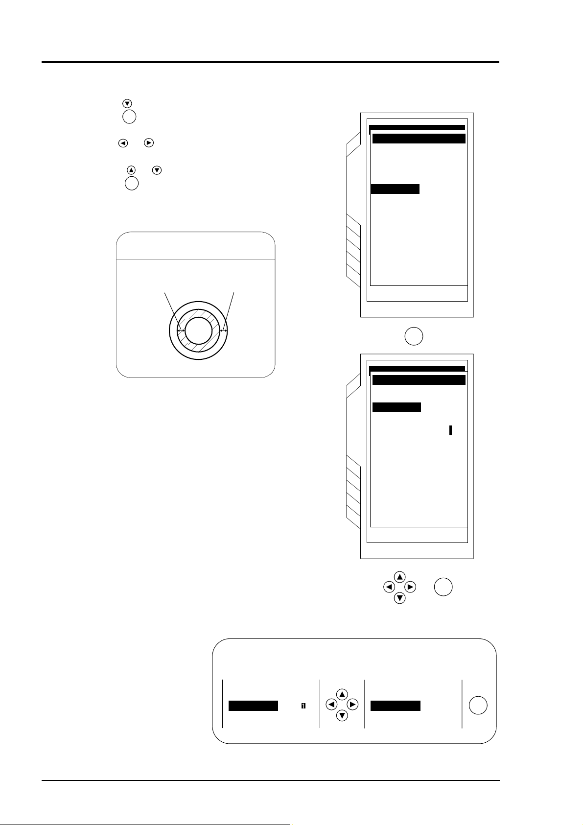
6.2 Entry of site name (measurement is possible without
BULLETIN F-68
entry)
Enter the name of the site (where measurement is performed). This name is registered with site memory
(r of page 6 - 2).
Select a character and press the
Then, select “CLOSE” and press the
you entered wrong characters, press the
ENT
key. Characters will be displayed one by one at top of the screen.
ENT
key to complete entry (up to 20 characters can be entered). If
ESC
key and characters can be cleared one by one.
SITE SETUPSITE SETUP
PIPE PARAMETERPIPE PARAMETER
SITE NAMESITE NAME
Close
Select "CLOSE"
and press the key
to compl
ENT
ete entry.
PIPE NO.1 is selected from SITE NAME.
SITE SETUPSITE SETUP
PIPE PARAMETERPIPE PARAMETER
SITE NAME
SITE NAME
OUTER DIAMETER
PIPE MATERIAL
WALL THICKNESS
LINING MATERIAL
SITE SETUP
LINING THICKNESS
KIND OF FLUID
SENSOR MOUNTING
SENSOR TYPE
PIPE NO. 1
13.00 m m
CARBON STEEL
0.01 m m
NO LINING
0.01mm
WATER
V
PSX2 B
1 TIMETRANS, VOLTAGE
6 - 3
Page 21
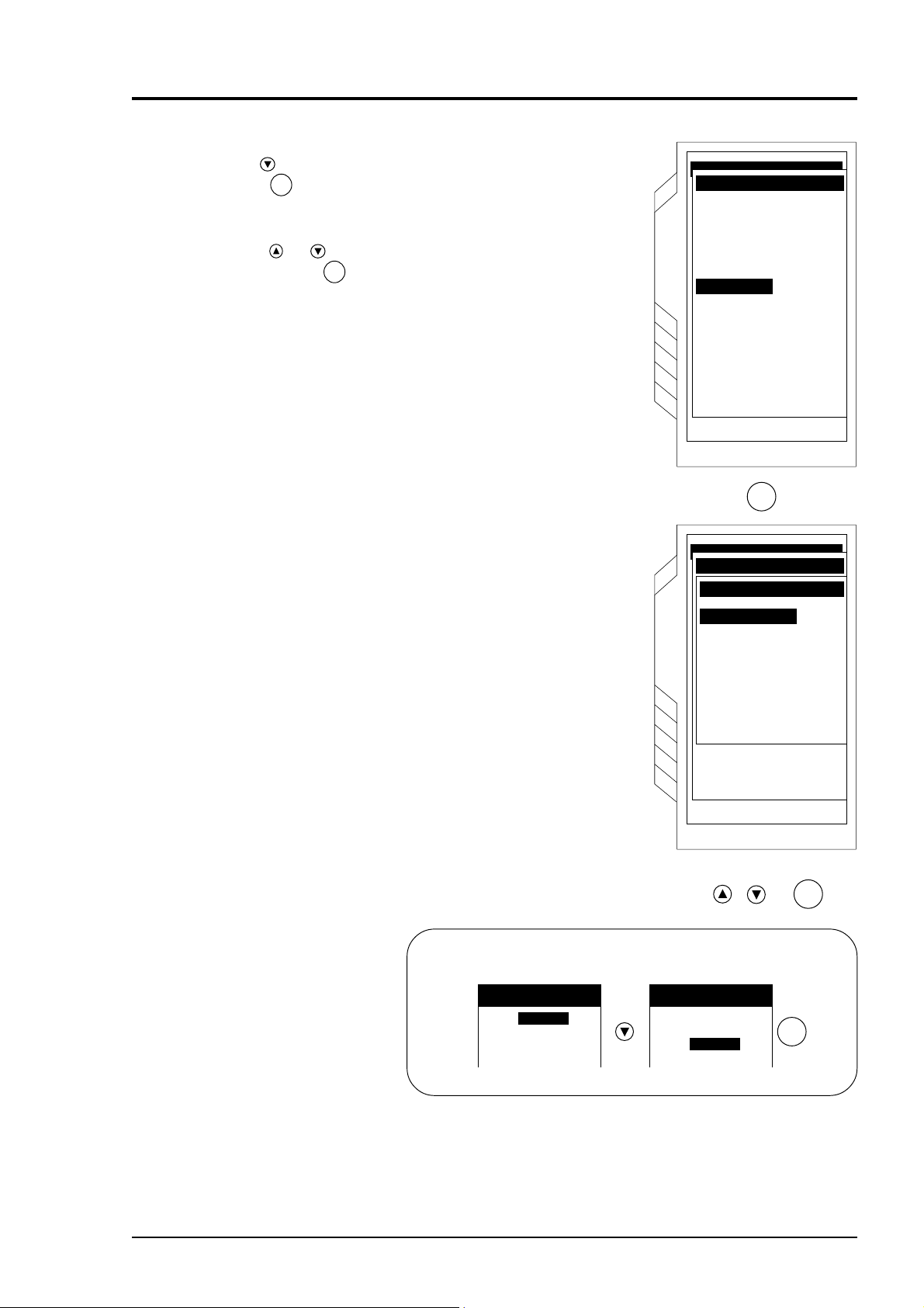
6.3 Outer diameter of piping (unit: mm)
BULLETIN F-68
(range: 13 to 6100 mm)
Press the key on the “PIPE PARAMETER” screen to
invert the “OUTER DIAMETER”.
Press the
Use the
ENT
key, and you can enter the outer dimension.
or key to cause the digit to move in the right
and left direction
Use the
After entry, press the
or key to enter the numeric.
ENT
key.
Note) Enter outer dimensions, but not nominal diameter
(example: 20A → 20).
Outer diameter of piping
Outer
diamerer
SITE SETUPSITE SETUP
PIPE PARAMETERPIPE PARAMETER
SITE NAME
OUTER DIAMETER
OUTER DIAMETER 13.00 m m
PIPE MATERIAL
WALL THICKNESS
LINING MATERIAL
SITE SETUP
LINING THICKNESS
KIND OF FLUID
SENSOR MOUNTING
SENSOR TYPE
SITE SETUPSITE SETUP
PIPE PARAMETERPIPE PARAMETER
SITE NAME
OUTER DIAMETEROUTER DIAMETER 0013.00 m m
PIPE MATERIAL
WALL THICKNESS
LINING MATERIAL
SITE SETUP
LINING THICKNESS
KIND OF FLUID
SENSOR MOUNTING
SENSOR TYPE
CARBON STEEL
NO LINING
ENT
CARBON STEEL
NO LINING
PIPE NO.1
0.01 m m
0.01 m m
WATER
V
PSX2 B
4 TIMESTRANS. VOLTAGE
0.01 m m
0.01 m m
WATER
V
PSX2 B
4 TIMESTRANS. VOLTAGE
6 - 4
ENT
Example) When the outer diameter of piping is 318.5 mm:
PIPE PARAMETER
SITE NAME
OUTER DIAMETEROUTER DIAMETER OUTER DIAMETEROUTER DIAMETER
0013.0 mm
PIPE PARAMETER
SITE NAME
0318.50mm
ENT
Page 22
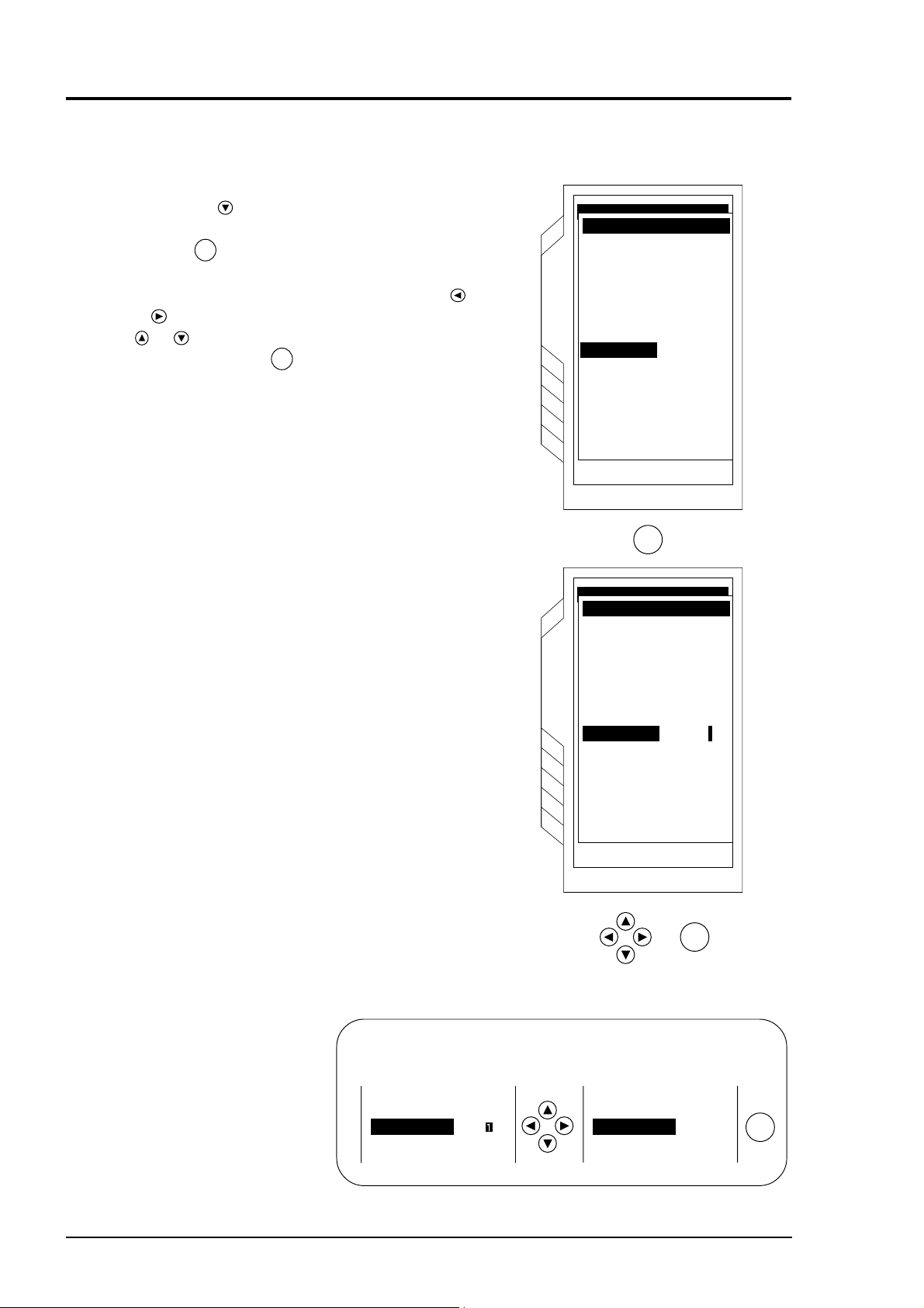
6.4 Piping material
BULLETIN F-68
Press the key to invert the “PIPE MATERIAL”.
Press the
Select the material by using the
the
Note) If you select “OTHER”, enter the sound velocity
ENT
key, and the “PIPE MATERIAL” screen will appear.
ENT
key.
(range: 1000 to 3700m/s). See page 15 - 6, Table @1.
or key. After entry, press
SITE SETUPSITE SETUP
PIPE PARAMETERPIPE PARAMETER
SITE NAME
OUTER DIAMETER
PIPE MATERIALPIPE MATERIAL
WALL THICKNESS
LINING MATERIAL
SITE SETUP
LINING THICKNESS
KIND OF FLUID
SENSOR MOUNTING
ENT
SITE SETUPSITE SETUP
PIPE PARAMETERPIPE PARAMETER
SITE NAME
PIPE MATERIALPIPE MATERIAL
OUTER DIAMETER
CARBON STEEL
CARBON STEEL
PIPE MATERIALPIPE MATERIAL
STAINLESS STEEL
WALL THICKNESS
LINING MATERIAL
SITE SETUP
LINING THICKNESS
KIND OF FLUID
SENSOR MOUNTING
SENSOR TYPE
TRANS, VOLTAGE
CAST IRON
COPPER
ALUMINUM
DUCTILE IRON
ASBESTOS
PIPE NO.1
318.50 m m
CARBON STEEL
0.01 m m
NO LINING
0.01 m m
WATER
V
PSX2 BSENSOR TYPE
4 TIMESTRANS. VOLTAGE
PVC
FRP
Example) When the piping material is cast iron:
PIPE MATERIALPIPE MATERIAL PIPE MATERIALPIPE MATERIAL
CARBON STEELCARBON STEEL
STAINLESS STEEL
CAST IRON
CARBON STEEL
STAINLESS STEEL
CAST IRONCAST IRON
ENT
ENT
6 - 5
Page 23
6.5 Wall thickness (unit: mm) (range: 0.01 to 100.00mm)
BULLETIN F-68
Press the key to invert the “WALL THICKNESS”.
Press the
pages 15 -1 to 15 - 6, Piping Data ).
Use the
left.
Using the
press the
ENT
key, and wall thickness can be entered (See
or key to move the digit to the right and
or key, enter the numeral. After entry,
ENT
key.
Lining and wall thickness of piping
SITE SETUPSITE SETUP
PIPE PARAMETERPIPE PARAMETER
SITE NAME
OUTER DIAMETER 318.50 m m
PIPE MATERIAL
WALL THICKNESS
LINING MATERIAL
SITE SETUP
LINING THICKNESS
KIND OF FLUID
SENSOR MOUNTING
SENSOR TYPE
CARBON STEEL
NO LINING
PIPE NO.1
0.01 m m
0.01mm
WATER
V
PSX2 B
4 TIMESTRANS. VOLTAGE
Lining thickness
Wall thickness
ENT
SITE SETUPSITE SETUP
PIPE PARAMETERPIPE PARAMETER
SITE NAME
OUTER DIAMETEROUTER DIAMETER 318.50 mm
PIPE MATERIAL
WALL THICKNESS
LINING MATERIAL
SITE SETUP
LINING THICKNESS
KIND OF FLUID
SENSOR MOUNTING
SENSOR TYPE
CARBON STEEL
NO LINING
0.01 mm
0.01 mm
WATER
V
PSX2B
4 TIMESTRANS. VOLTAGE
6 - 6
ENT
Example) When the wall thickness is 1.25mm
PIPE MATERIAL CAST IRON
WALL THICKNESS
LINING MATERIAL NO LINING
000.0 mm
PIPE MATERIAL CAST IRON
WALL THICKNESS
LINING MATERIAL NO LINING
001.25mm
ENT
Page 24
6.6 Lining material
BULLETIN F-68
Press the key to invert “LINING MATERIAL”.
Press the
ENT
key, and “LINING MATERIAL”
screen will appear.
Using the
selection, press the
or key, select the material. After
ENT
key.
Note) If you select “OTHER”, enter the sound velocity
(range 1000 to 3700m/s). See page 15-6,
Table @1.
SITE SETUPSITE SETUP
PIPE PARAMETERPIPE PARAMETER
SITE NAME
OUTER DIAMETER
PIPE MATERIAL
WALL THICKNESS
LINING MATERIAL
LINING MATERIAL
SITE SETUP
LINING THICKNESS
KIND OF FLUID
SENSOR MOUNTING
ENT
SITE SETUPSITE SETUP
PIPE PARAMETERPIPE PARAMETER
SITE NAME
LINING MATERIALLINING MATERIAL
OUTER DIAMETER
PIPE MATERIALPIPE MATERIAL
WALL THICKNESS
LINING MATERIAL
SITE SETUP
LINING THICKNESS
KIND OF FLUID
SENSOR MOUNTING
SENSOR TYPE
TRANS. VOLTAGE
NO LINING
NO LINING
TAR EPOXY
MORTAR
PYREX GLASS
PIPE NO.1
318.50 m m
CAST IRON
1.25 m m
NO LINING
0.01 m m
WATER
V
PSX2 BSENSOR TYPE
4 TIMESTRANS. VOLTAGE
RUBBER
TEFLON
OTHER 2000 m/s
ENT
Example) When the lining material is mortar
LINING MATERIALLINING MATERIAL LINING MATERIALLINING MATERIAL
NO LININGNO LINING
TAR EPOXY
MORTAR
ROBBER
LINING MATERIAL
NO LINING
TAR EPOXY
MORTAR
MORTAR
ROBBER
ENT
6 - 7
Page 25
6.7 Lining thickness (unit: mm) (range: 0.01 to 100.00 mm)
BULLETIN F-68
When the lining material is set to items other than
“None” in 6.6 Lining material.
Press the
THICKNESS”.
Press the
can be performed.
The cursor can shift the numeric digit by using the
or key. The numeric can be entered by using the
or key.
After entry, press the
key to invert the “LINING
ENT
key, the lining thickness numeric entry
ENT
key.
SITE SETUPSITE SETUP
PIPE PARAMETERPIPE PARAMETER
SITE NAME
OUTER DIAMETER 318.50 m m
PIPE MATERIAL
WALL THICKNESS
LINING MATERIAL
SITE SETUP
LINING THICKNESS
KIND OF FLUID
SENSOR MOUNTING
SENSOR TYPE
CARBON STEEL
NO LINING
ENT
PIPE NO.1
0.01 m m
0.01mm
WATER
V
PSX2 B
4 TIMESTRANS. VOLTAGE
SITE SETUPSITE SETUP
PIPE PARAMETERPIPE PARAMETER
SITE NAME
OUTER DIAMETER 318.50 m m
PIPE MATERIAL
WALL THICKNESS
LINING MATERIAL
SITE SETUP
LINING THICKNESS
KIND OF FLUID
SENSOR MOUNTING
SENSOR TYPE
CARBON STEEL
0.01 m m
NO LINING
000.01mm
WATER
V
PSX2 B
4 TIMESTRANS. VOLTAGE
ENT
Example) When the lining thickness is 1.25 mm
6 - 8
LINING MATERIAL MORTAR
LINING THICKNESSLINING THICKNESS
KIND OF FLUID
000.0 mm
WATER
LINING MATERIAL MORTAR
LINING THICKNESSLINING THICKNESS
KIND OF FLUID
001.25mm
WATER
ENT
Page 26
6.8 Kind of fluid
BULLETIN F-68
Select kind of fluid and enter the dynamic viscosity
coefficient.
For fluid having no item, enter sound velocity.
(Range: 500 to 2500 m/s)
Press the key to invert the “KIND OF FLUID”.
Press the
will appear.
Note 1) To return the screen to the “PIPE
Select kind of fluid by using the
After selection, press the
appear, to enter the dynamic viscosity coefficient.
The initial value is set to water coefficient.
ENT
key. The “KIND OF FLUID” screen
PARAMETER”, press the
ESC
key.
or key.
ENT
key, the screen will
SITE SETUPSITE SETUP
PIPE PARAMETERPIPE PARAMETER
SITE NAME
OUTER DIAMETER
PIPE MATERIAL
WALL THICKNESS
LINING MATERIAL
SITE SETUP
LINING THICKNESS
KIND OF FLUIDKIND OF FLUID
SENSOR MOUNTING
PIPE NO.1
318.50 m m
CAST IRON
1.25 m m
MORTAR
1.25mm
WATER
V
PSX2 BSENSOR TYPE
4 TIMESTRANS. VOLTAGE
CAUTION
There is no need to change “1.004 E-6m
when measuring water. Return the screen by
pressing the
ESC
key.
Note 2) When “OTHER” is selected, enter sound ve-
locity. See page 15-6, Tables 20 and 22.
Remarks
Dynamic viscosity coefficient is set to water (20°C).
When measuring accurately or measuring fluid other than
water, enter as needed.
(See page 15-6.)
(Range: 0.001 × 10
SITE SETUPSITE SETUP
PIPE PARAMETERPIPE PARAMETER
KIND OF FLUIDKIND OF FLUID
WATER
WATER
SEA WATER
OTHER
-6
to 999.999 × 10⁻⁶m2/s)
SITE SETUPSITE SETUP
PIPE PARAMETERPIPE PARAMETER
ENT
ESC
ENT
ESC
KIND OF FLUIDKIND OF FLUID
WATERWATER
KINEMATIC VISCOSITYKINEMATIC VISCOSITY
1.003 E -6 m 2 / s
SITE SETUPSITE SETUP
PIPE PARAMETERPIPE PARAMETER
KIND OF FLUIDKIND OF FLUID
OTHEROTHER
SOUND VELOCITYSOUND VELOCITY
2500 m / s
KINEMATIC VISCOSITY
1.003 E -6 m 2 / s
2
/s”
"WATER"
"OTHER"
ENT ESC
KIND OF FLUIDKIND OF FLUID
WATERWATER
SEA WATER
OTHER
SITE SETUP
ENT ESC
WATERWATER
KINEMATIC VISCOSITYKINEMATIC VISCOSITY
1.004E-6 m2/s
SITE SETUP
6 - 9
Page 27
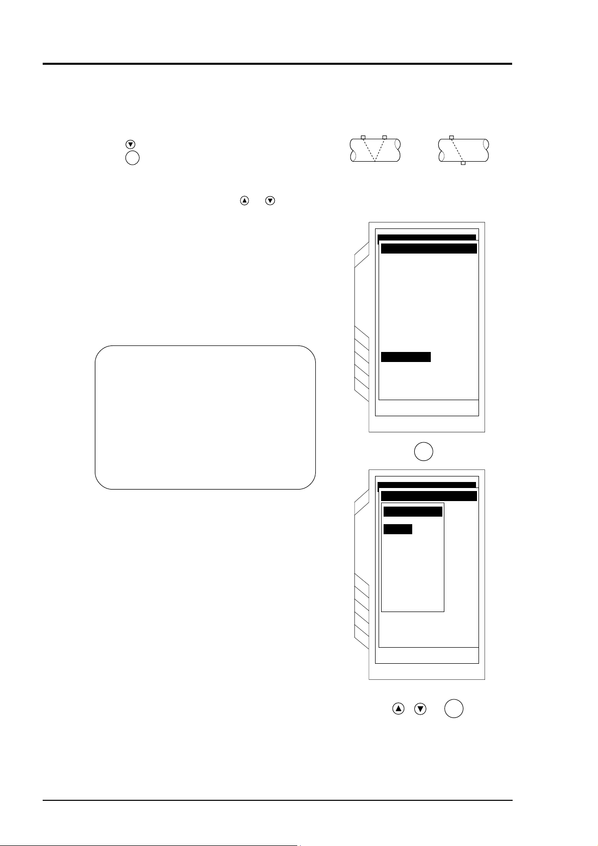
6.9 Selection of sensor mounting method
BULLETIN F-68
Mounting methods available for the sensor are V method
and Z method as illustrated.
To select the mounting method;
Press the
Press the
key to invert the “SENSOR MOUNTING”.
ENT
key. The “SENSOR MOUNTING” screen
will appear.
V method
Z method
Select either V or Z method using the
or key.
Remarks
Select the V method generally. Use the Z method in
the following cases:
• Ample space is not provided.
• High turbidity
• Weak receiving waveform
• Thick scale is deposited on the pipe internal
surface.
SITE SETUPSITE SETUP
PIPE PARAMETERPIPE PARAMETER
SITE NAME
OUTER DIAMETER
PIPE MATERIAL
WALL THICKNESS
LINING MATERIAL
SITE SETUP
LINING THICKNESS
KIND OF FLUID
SENSOR MOUNTING
SENSOR MOUNTING
ENT
SITE SETUPSITE SETUP
PIPE PARAMETERPIPE PARAMETER
SITE NAME
SENSOR MOUNTINGSENSOR MOUNTING
OUTER DIAMETER
V
PIPE MATERIALPIPE MATERIAL
Z
WALL THICKNESS
LINING MATERIAL
SITE SETUP
LINING THICKNESS
KIND OF FLUID
SENSOR MOUNTING
SENSOR TYPE
TRANS. VOLTAGE
PIPE NO.1
318.50 m m
CAST IRON
1.25 m m
MORTAR
1.25mm
WATER
V
PSX2 BSENSOR TYPE
4 TIMESTRANS. VOLTAGE
6 - 10
ENT
Page 28
6.10 Kind of sensor
BULLETIN F-68
Press the key to invert “SENSOR TYPE”.
Press the
Select any sensor from the type code of sensor to be used.
Select the sensor by using the
ENT
key to display kind of sensor.
or key.
SITE SETUPSITE SETUP
PIPE PARAMETERPIPE PARAMETER
SITE NAME
OUTER DIAMETER
PIPE MATERIAL
WALL THICKNESS
LINING MATERIAL
SITE SETUP
LINING THICKNESS
KIND OF FLUID
SENSOR MOUNTING
SENSOR TYPE
ENT
SITE SETUPSITE SETUP
PIPE PARAMETERPIPE PARAMETER
SITE NAME
SENSOR TYPE
OUTER DIAMETER
PIPE MATERIALPIPE MATERIAL
WALL THICKNESS
LINING MATERIAL
SITE SETUP
LINING THICKNESS
KIND OF FLUID
SENSOR MOUNTIN
SENSOR TYPE
TRANS, VOLTAGE
PSX2 E
PSX2 HT
PSX2 C/SX1 B
SX1 C
PSX2 D
PSX2 A
B
PSX2
PSX2 CG
PIPE NO.1
318.50 m m
CAST IRON
1.25m m
MORTAR
1.25mm
WATER
V
PSX2 BSENSOR TYPE
4 TIMESTRANS. VOLTAGE
ENT
Example) When model of sensor is PSX2 A
SENSOR TYPE SENSOR TYPESENSOR TYPE
PSX2 E PSX2E
PSX2A
PSX2B
PSX2A
PSX2B
ENT
6 - 11
Page 29
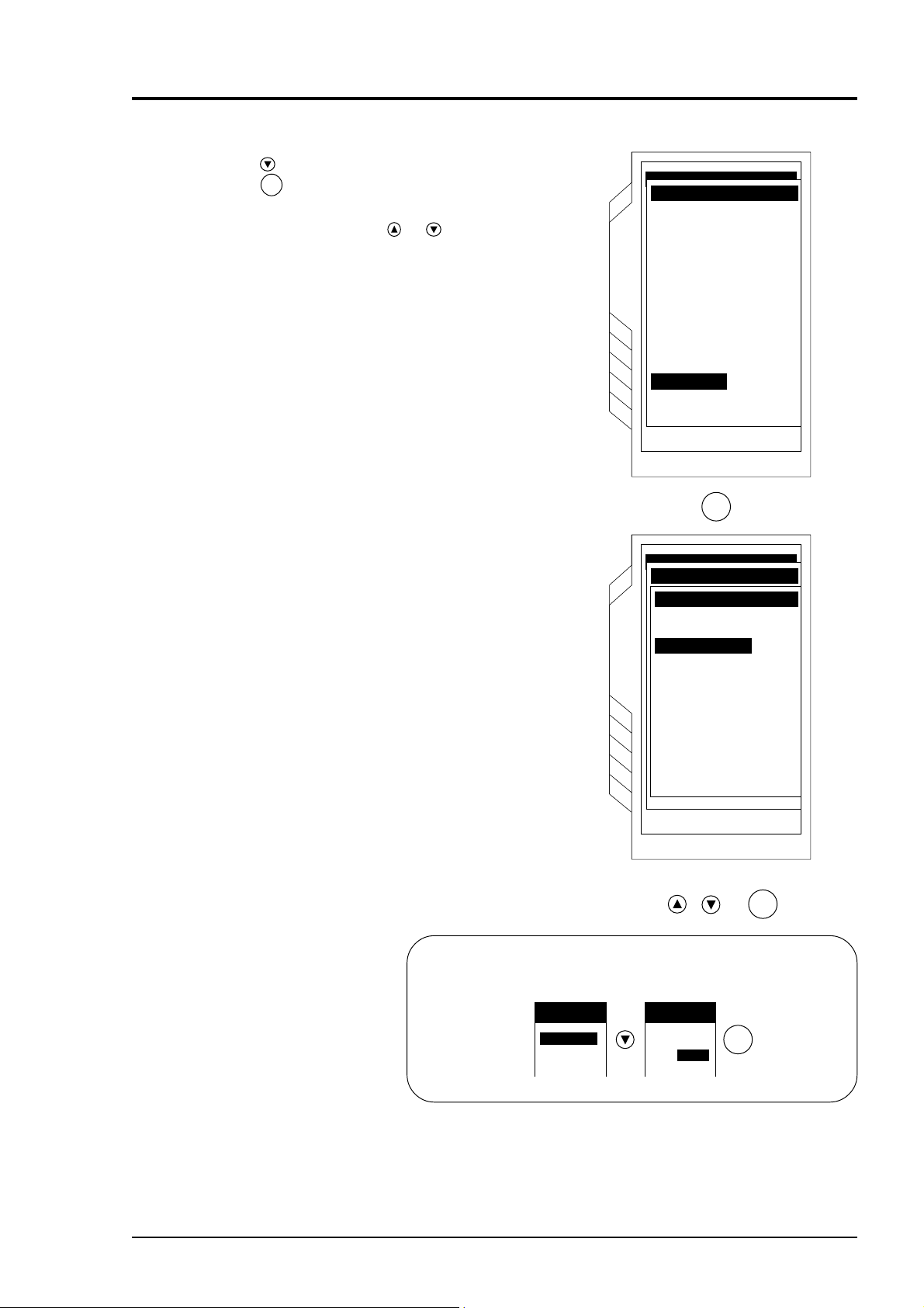
6.11 Transmission voltage (used when an indicator is 1 or
BULLETIN F-68
less during measurement)
SITE SETUPSITE SETUP
Press the key to invert the “TRANS. VOLTAGE”.
Press the
ENT
key. The screen is ready to allow the
selection of the transmission voltage level.
Use the
or key to select the level.
Select “4 TIMES” or “8 TIMES” generally.
CAUTION
If the indicator cannot be set to 2 or more
with the level at “8 TIMES”, ultrasonic wave
may be attenuated due to contamination or
scales deposited on the piping external and
internal surfaces. Change measurement
location.
Example)When transmission voltage
is set to eight-fold
TRANS. VOLTAGE TRANS. VOLTAGE
1
TIME
2
TIMES
4
TIMES
8
TIMES
1
TIME
2
TIMES
4
TIMES
8
TIMES
ENT
PIPE PARAMETERPIPE PARAMETER
SITE NAME
OUTER DIAMETER
PIPE MATERIAL
WALL THICKNESS
LINING MATERIAL
SITE SETUP
LINING THICKNESS
KIND OF FLUID
SENSOR MOUNTING
TRANS. VOLTAGE
ENT
SITE SETUPSITE SETUP
PIPE PARAMETERPIPE PARAMETER
SITE NAME
TRANS. VOLTAGETRANS. VOLTAGE
OUTER DIAMETER
PIPE MATERIALPIPE MATERIAL
WALL THICKNESS
LINING MATERIAL
SITE SETUP
LINING THICKNESS
KIND OF FLUID
SENSOR MOUNTING
SENSOR TYPE
TRANS, VOLTAGE
1 TIME
2 TIMES
4 TIMES4 TIMES
8 TIMES
PIPE NO.1
318.50 m m
CAST IRON
1.25 m m
MORTAR
1.25mm
WATER
V
PSX2 ASENSOR TYPE
4 TIMESTRANS. VOLTAGE
6 - 12
The indicator will be updated on the
“MEASURE” screen only.
If less than 2 indicators (intensity of receiving
waveform) are displayed on the “MEASURE” screen,
raise the transmission voltage.
ENT
Indicator
95-06-27 11:49
FLOW RATE UNIT: m3/h
x10
VELOCITY UNIT: m/s
MEASURE
x10
+ TOTAL UNIT: ml
STOP
RESET
Page 30
7. MOUNTING OF DETECTOR
BULLETIN F-68
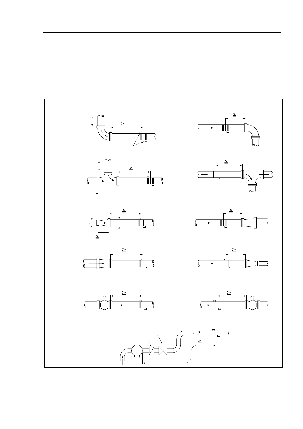
7.1 Selection of mounting location
Detector mounting location, i.e., the conditions of the pipe subjected to flow rate measurement exert a
great influence on measurement accuracy. So select a location meeting the conditions listed below.
(1) There is a straight pipe portion of 10D or more on the upstream side and that of 5D or more on the
downstream side.
(2) No factors to disturb the flow (such as pump and valve) within about 30D on the upstream side.
Classification For upstream side For downstream side
L5D
90° bend
Tee
Diffuser
Reducer
More than 10D
More than
More than
10D
0.5D
More than
10D
1.5D
L 10D
Detector
L 50D
L 30D
D
L 10D
L 10D
L5D
L5D
L 30D
Valves
Flow control valve exists on upstream side.
Stop valve
Check valve
Pump
Flow control valve exists on downstream side.
L 50D
P
Extracted from Japan Electric and Machinery Industry Society (JEMIS-032)
L 10D
7 - 1
Page 31

(3) Pipe is always filled with fluid. Neither air bubbles nor foreign materials are contained in the fluid.
BULLETIN F-68
(4) There is an ample maintenance space around the pipe to which the detector is to be mounted (see
figure below).
Note 1) Secure an adequate space for allowing a person to stand and work on both sides of a pipe.
Note 2) D indicates the inside diameter of a pipe.
200
or more
Note
2000 or more
200
or more
D + 1200 or more 600 or more
D
600 or more
D : Pipe diameter
Space required for mounting detector
(5) For a horizontal pipe, mount the detector within ±45° of the horizontal plane.
For a vertical pipe, the detector can be mounted at any position on the outer circumference.
Air bubbles
Pipe
45°
Horizontal plane
45°
Deposits of
sludge
(6) Avoid mounting the detector near a deformation, flange or welded part on the pipe.
7 - 2
Welded part Welded part
Flange or welded
Page 32

7.2 Selection of detector
BULLETIN F-68
(1) Selection of mounting methods
There are 2 methods for mounting the detector; V method and Z method. For the mounting space, see
the following sketch.
<Large sensor>
L=About D
Detector
D
D
V method
<Small diameter sensor, small sensor or high-temperature sensor>
Length of frame of each sensor
L
V method Z method
Frame
Mounting method
D
Length of frame of each sensor
L=About D/2
Detector
Z method
L
L: Mounting dimension
mounting dimension for
sensor displayed on the
SITE SETUP screen
Employ the Z method in the following cases.
• Mounting space need be saved (mounting space of the Z method is about one half of the V
method's).
• Turbid fluid such as sewage is to be measured.
• Pipe has mortar lining.
• A thick film of scale may have been formed on the inner surface of pipe because it is old.
(2) Detector selection standards
The Z method for large size sensor is recommended for outer diameter 300mm or more.
PSX2 D should be used as much as possible for pipes such as old pipes, cast iron pipes, and mortar
lining pipes, through which it is difficult for ultrasonic signals to pass.
Detector
Type Diameter Temperature
PSX2 B
PSX2 A/E
PSX2 HT
PSX2 D
13 100mm (V method)
50 350mm (V method)
300 400mm (Z method)
50 350mm (V method)
300 400mm (Z method)
200 3000mm (V method)
200
6000mm
(Z method)
-40 +100°C
-40 +100°C
-40
-40 +80°C
+200°C
7 - 3
Page 33

7.3 Use of surface-treated accessories
BULLETIN F-68
Eliminate pitting, corrosion, unevenness, etc. with paint thinner and sandpaper from the pipe portion
where the detector is to be mounted.
Note) In case jute is wound on a pipe, it should be peeled off before the above treatment.
When cast iron pipe is used, grind the sensor mounting surface by using a sander for smoothness.
Detector Width
Small outer
diameter
Small size
(standard) sensor
PSX2A
Large size sensor
PSX2D
High temperature
PSX2 HT
PSX2B
320 mm or more
540 mm or more
Mounting dimension
(L) + 200 mm or more
530 mm or more
Jute is wound
Pipe
Width
7 - 4
Page 34

7.4 How to mount small size (standard) sensor and small
BULLETIN F-68
outer diameter sensor to pipe
q Loosen the lock nut and slide the sensor so as to
meet the mounting dimension and then tighten
the nut.
w Apply a coat of silicone grease to the
transmitting surface of the sensor. Spread the
compound over the entire area.
Keep the sensor retracted by turning the element
holder counterclockwise.
After cleaning the surface of the pipe, the sensor
should be mounted.
Lock nut
Element holdder
BNC connector
Scale
Frame
Transmitter unit
Saddle
Cursor
Mounting
dimension (L)
CAUTION
Apply a small quantity (like toothpaste) of
silicon grease to the transmitter unit.
e Fix the both ends (saddles) of the sensor to the
pipe by cloth belts.
Mounting will be facilitated by winding the cloth
belts on the pipe in advance.
Cloth belts are usable at 80°C or lower. If
beyond 80°C, stainless steel belts should be
used.
(
)
r Make sure the sensor is mounted in parallel with
the pipe axis and the mounting dimension is
right. Then, turn the element holder clockwise
until the sensor comes in close contact with the
pipe.
Stop turning the element holder when it stiffens
because the transmitting surface comes in
contact with the pipe surface. Be careful not to
turn the holder excessively.
Element holder
Cloth belt
Cable
Element holder
7 - 5
Page 35

7.5 How to mount large size sensor
BULLETIN F-68
7.5.1 How to determine mounting position (large sensor)
Determine the mounting position by carrying out the following work.
For this work, gauge paper is necessary (For the gauge paper, refer to page 7-10).
q Match the edge of gauge paper with the line at
about 100mm from one end of the pipe portion
treated for detector mounting, and wind the
gauge paper so that the line marked on the paper
is parallel with the pipe axis (fix with tape not to
allow deviation). At this time, the edge of gauge
paper should be aligned.
w Extending the line marked on the gauge paper,
mark straight line A on the pipe.
e Mark a line along on edge of the gauge paper.
The intersection of this line and straight line A is
replaced with A
.
0
r In mounting by the V method, peel the gauge
paper and measure the mounting dimension from
A0 to determine A2 position. At this position,
mark a line orthogonal to the straight line A.
Line drawn
on gauge paper
Draw line A.
Draw a line
along the edge.
A
2
100mm
Align this edge.
A
0
A
0
A0 and A2 become the mounting positions.
Example) L = 200mm
t In mounting by the Z method, measure the
circumference from A
with a measuring tape.
0
At 1/2 of the circumference, determine points B
and B1, and mark a line (straight line B)
connecting those points.
y Mark the points B
Measure the mounting dimension from B
and peel off the gauge paper.
0
0
to
determine B2 position. At this position, make a
line orthogonal to the straight line B.
A0 and B2 become the mounting positions.
Example) L = 100mm
200mm
A
B
A
0
1
B
1
B
2
B
0
A
0
Straight line B
100mm
B
0
0, B1
A
0
B
B
0
0, A1
2
7 - 6
Page 36

7.5.2 How to connect large size sensor for PSX2 D type only
BULLETIN F-68
q Slide the detector cover slightly. Remove the
cover with a driver.
w Determine the mounting posture of sensor on the
pipe.
Align the transmission direction marks.
Cover
Transmission direction mark
Transmission direction mark
e Put a mark on the inlet of coaxial cable.
When the pipe is horizontally installed with the
detector, allow the coaxial cable to be suspended
to prevent entry of water from the cable inlet.
When the pipe installed vertically, it does not
matter how the coaxial cable should be installed.
Note) Upstream and downstream sensors
should be able to be distinguished.
r Connect the coaxial cable to terminal (G, +) and
fix it with the cable clamp.
Cable retainer
Rubber bush
t Replace the cover.
7 - 7
Page 37

7.5.3 How to mount large size sensor to pipe
BULLETIN F-68
qq
q Height adjustment of guide plate
qq
• Place the sensor on the pipe surface in parallel
with the pipe axis.
• Loosen the guide plate fixing screw and slide
the guide plate until its edge and transmitting
surface touch the surface of pipe.
Transmission
surface
Fixing screw
Guide plate
Pipe
• Then tighten the fixing screw.
ww
w How to determine the length of wire rope
ww
• Place the sensor on the marked lines and fit the
wire rope and fastening spring.
• Loosen the wire clip and pull the wire rope
until the overall length of fastening spring
approximates 180mm. Then tighten the wire
clip.
(The fastening spring has a free length of
110mm.)
• While fixing the wire rope, remove the sensor.
ee
e Mounting of sensor
ee
• Wipe off contaminants from the transmitting
surface of sensor and the sensor mounting
surface of pipe.
• Apply the silicone grease on the transmitting
surface of sensor wile spreading it evenly.
• Film thickness of the silicone grease should be
about 3mm.
• Spread the wire rope near the marked lines in
the left-right direction, bring the sensor in
close contact and fit the wire rope.
Fastening
spring
600
Tramsmitting
180
Sensor
surface
Transmission
direction mark
Loosen this wire clip
and pull the wire rope.
Marked lines
Pipe
• Align the matching mark of sensor with the
marked line. In addition, make the
transmitting direction marks of sensors face
each other.
• Make sure the matching mark of sensor is
aligned with the marked line and connect the
coaxial cable to the converter.
Note) Do not pull the coaxial cable.
Otherwise, the sensor will be
activated to disturb measurement.
Fastening spring
Marked line
Sensor
Pipe
Transmission mark
Marked line
Matching mark
Transmission
mark
dimension (L)
Marked lline
Mounting
Matching
mark
7 - 8
Page 38

7.6 How to mount high temperature sensor to pipe
BULLETIN F-68
q Loosen the lock nut and slide the sensor so as to
meet the mounting dimension and then tighten
the nut.
w Apply a coat of grease for high temperature to
the transmitting surface of the sensor. Spread the
compound over the entire area.
Keep the sensor retracted by turning the element
holder counterclockwise.
After cleaning the surface of the pipe, the sensor
should be mounted.
BNC connecot
Frame
High temperature
grease
Lock nut
Scale
Element holder
Cursor
Mounting
dimension
(L)
Spatula
Transmission
unit
Saddle
e Fix the both ends (saddles) of the sensor to the
pipe by stainless belts.
r Make sure the sensor is mounted in parallel with
the pipe axis and the mounting dimension is
right. Then, turn the element holder clockwise
until the sensor comes in close contact with the
pipe.
Stop turning the element holder when it stiffens
because the transmitting surface comes in
contact with the pipe surface. Be careful not to
turn the holder excessively.
Stainless belt
Stainless belt
Element
holder
Cable
7 - 9
Page 39

7.7 How to mount medium diameter sensor to pipe
BULLETIN F-68
q Spread silicone grease over the whole
transmitting side of the sensor. Care should be
taken to prevent entry of air bubbles.
Clean the surface of the pipe, then mount the
sensor.
w Press the sensor against the pipe. Align the
center of the sensor with the intersection of the
marking line, and the mounting dimension
reference surface with the marking line.
Silicone grease
e Make sure that the center mark on the sensor is
aligned with the marking line. Then, connect the
coaxial cable to the transmitter.
Note) Do not pull the coaxial cable. If it is
pulled, the sensor is shifted which
results in incorrect measurements due to
poor contact with the pipe.
7.8 How to fold gauge paper
(used for determining mounting position)
q Prepare a sheet of paper (vinyl sheet) of 4 D or
more in length and 200 mm or longer in width (D
is preferable) as shown below.
w Draw a line intersecting at right angles with the
longest sides about 100 mm from one paper end.
To be aligned
Marking line
4D
Parallel
Center mark
200 mm or
D or larger
About 100 mm
7 - 10
Page 40

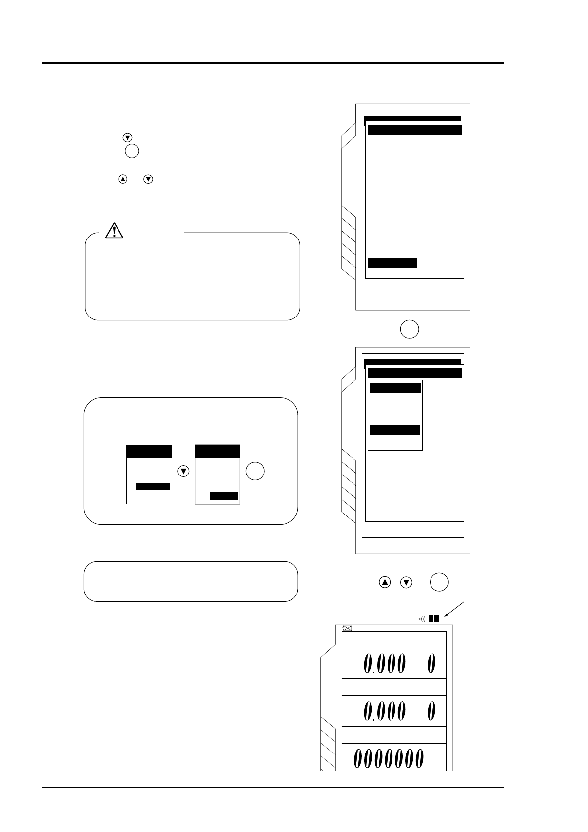
8. MEASUREMENT
BULLETIN F-68
When wiring, piping settings and mounting of the sensor are completed, start the measurement.
The contents displayed on the MEASURE screen are as follows.
Instantaneous flow meter
⋅ On the MEASURE screen, instantaneous flow, instantaneous flow velocity, analog output, and analog input
are displayed.
Of the 4 stages displayed on the MEASURE screen, 2 contents can be arbitrarily allocated to the 1st and 2nd
stage. Allocation is accomplished by selection of “UNIT”.
If the flow rate is displayed when water flow stops, refer to page 9-3, “ZERO ADJUST” and page 9-5,
“CUT OFF”.
If the flow display fluctuates, refer to page 9-3 “RESPONSE SET”.
Integrated flow rate
⋅ When the integrated flow rate is displayed, “+TOTAL” and “-TOTAL” are fixed on the third stage and 4th
stage, respectively.
⋅ Integrated flow rate value is available in the range from 0000000 to 999999. If the value exceeds 9999999,
it resets to 0000000.
Instantaneous flow rate,
flow velocity, etc.
How to view display
x10
Mantissa Exponent
X10 0 =1 time
1
=10 times
X10
2
=100 times
X10
Example)
When the cursor points to
the "MEASURE"
Tab as displayed, use
care since the measurement value will not
change.
Move the cursor within
the screen by pressing
the key.
1.200
corresponds to
1.2X10=12.
x10
Battery alarm
95-06-27 11:49
FLOW RATE
UNIT: m3/h
x10
VELOCITY UNIT: m/s
MEASUREMEASURE
1
x10
+ TOTAL UNIT: mL
- TOTAL
NORMAL
Status display
Integrated flow rate in forward direction
Integrated flow rate in reverse direction
UNIT: mL
IndicatorClock
Unit of indication
value
UNIT
L/s
L/min
L/h
ML/d
m3/s
m3/min
m3/h
Mm3/d
BBL/s
BBL/min
BBL/h
STOP
RESET
STOP
RESET
Resetting of integrated flow rate
MBBL/d
m/s
AI %
AO %
Unit of totalize
Status display of
totalize
Instantaneous
flow rate
Instantaneous
flow velocity
Analog input
Analog output
8 - 1
Page 41

qq
BULLETIN F-68
q “Indicator”
qq
Shows the intensity of ultrasonic receiving signal.
Check if 2 or more indicators are displayed.
If one or less indicator is displayed, raise the transmission voltage level as shown on page 6-12.
When the sensor is not connected, the indicator may be lighted by sensing noises. But, this is not
an error.
ww
w “Status display”
ww
Check if “NORMAL” is displayed. If the sensor is not connected, other messages may be displayed.
This is not an error.
In case other message is displayed after installing and connecting the sensor, take corrective actions
according to page 9-33, “System check function”.
If “NORMAL” is not displayed when 1 or less indicator is display, refer to page 11-2, “Error in
measured value”.
ee
e “Battery alarm”
ee
When activating this instrument on the built-in battery, check if the BATTERY ALARM ( ) is not
displayed. If “BATTERY ALARM” is displayed, the power is turned OFF in about 20 minutes.
When charging the battery, refer to page 4-1 “To charge the battery”.
rr
r Unit of integration
rr
When changing the unit of integration, refer to page 9-6, “TOTALIZE: when performing the
integration process of measured data (totalize)”.
tt
t Unit of indication value
tt
To change the units of flow rate and flow
velocity on the MEASURE screen;
q Move the cursor to “UNIT” by pressing the
key.
or
ENT
w Press the
key, and the screen
appears, enabling the unit of flow rate to be
selected. Select any unit by pressing the
key and press the
or
yy
y Status display of integration
yy
ENT
Meaning of display
STOP: Not totalized
RUN: Totalizing in progress
To start the action of integration, refer to page
key.
FLOW RATE UNIT: m3/h
x10
VELOCITY UNIT: m/s
MEASURE
x10
+ TOTAL UNIT: ml
– TOTAL UNIT: ml
NORMAL
STOP
RESET
STOP
RESETRESET
Point the cursor to
UNIT of flow rate
and press the
key, and Menu
screen is displayed.
9-6, “TOTALIZE”.
uu
u “Clock set”
uu
This instrument has a timer function. For the
timer to set the time, refer to page 9-15,
FLOW RATE UNIT: m3/h
“CLOCK SET”.
The timer function should be used based on this
watch.
ii
i Reset
ii
The integration value can be set to 0 or “any
other numeric value”. To reset the integration
value, point the cursor to “RESET” by pressing
or
the
key, and then press the
When you want to reset to any value or 1000 for
example, refer to page 9-7, “To set reset data”.
ENT
key.
VELOCITY UNIT: m/s
MEASURE
+ TOTAL UNIT: ml
– TOTAL UNIT: ml
NORMAL
x10
x10
STOP
RESETRESET
STOP
RESET
Point the cursor to
RESET and press
ENT
the key,
and totalize is
reset.
ENT
UNITUNIT
L/s
L/min
L/h
ML/d
m3/s
m3/min
m3/h
Mm3/d
BBL/s
BBL/min
BBL/h
MBBL/d
m/s
AI %
AO %
8 - 2
Page 42

9. SETTING OPERATION (APPLICATION)
BULLETIN F-68
This section describes an outline and page configuration of each function page
SITE SETUPSITE SETUP
Condition settings for
measurement
SITE SETUP
PARAMETER MEMORY
PIPE PARAMETER
ZERO ADJUST
RESPONSE SET
SITE SETUPSITE SETUP
CALIBRATION
CUT OFF
TOTALIZE
--- SENSOR SPACING ---
126.7mm
MANUAL ZERO
0 s e c
0 . 0 0 0 m/s
ANALOG
Settings of analog input
and output
ANALOG IN /OUT
INPUT
DISPLAY
INPUT RANGE
ADJUST
OUTPUT
DISPLAY
ANALOGANALOG
RANGE UNIT
OUTPUT RANGE
OUTPUT MODE
BURN-OUT
ADJUST
0.000E0
m/s
1.000E0
0.8-4-20mA
HOLD
LOGGERLOGGER
Saving of measured value to
memory, and display and
output of data
FIow Site.
**
**
**
**
**
**
**
**
REMAIN
255 BLOCK
LOG NAME
EMPTY
**
EMPTY
**
EMPTY
**
EMPTY
**
EMPTY
**
EMPTY
**
EMPTY
**
EMPTY
**
DATA
MODE
SETUP
No
1
2
3
LOGGERLOGGER
4
5
6
7
8
9
10
PRINTERPRINTER
Various outputs on printer
MODE
TEXT
UNIT
TIMER MODE
PRINTER
SAMPLING PERIOD
PRINT OUT
FLOW RATE
VELOCITY
+ TOTAL
— TOTAL
ANALOG IN OFF
OFF
OFF
OFF
TIMER
00:00:01
SYSTEM SETUP
Change of basic system
settings of main unit
SYSTEM SETUP
CLOCK SET
COMMUNICATION
SYSTEM SETUP
SYSTEM OF UNITS
MEASUREMENT METHOD
MEMORY INITIALIZE
95-06-25 15 : 17 : 00
BAUD RATE
PARITY
STOP BIT
300
NONE
1 BIT
METRIC
1
SYSTEM CHECKSYSTEM CHECK
Check function of
device status
SYSTEM CHECK
ERROR CHECK
SIGNAL CHECK
OUTPUT CHECK 0.00%
VERSION NUMBER
SYSTEM CHECKSYSTEM CHECK
9 - 1
Page 43

9.1 How to use SITE SETUP function (SITE SETUP page)
BULLETIN F-68
9.1.1 PARAMETER MEMORY: when registering data which are set and calibrated on the page
“P ARAMETER MEMOR Y” allo ws you to register data which are set and calibrated on the “SITE SETUP”
page to the memory of the main unit.
When measurements are performed in the same pipe, registered data can be loaded to help you in achieving measurements. (Up to 20 registrations of data can be made to the memory.)
MODE
[Operation]
q Select “PARAMETER MEMORY” by
pressing the
SETUP page.
Press the
“PARAMETER MEMORY” screen is
displayed. To return to the “SITE
SETUP” screen, press the
or
ENT
key, and the
key on the SITE
ESC
key.
SITE SETUP
PARAMETER MEMORY
PIPE PARAMETER
ZERO ADJUST
RESPONSE SET
SITE SETUPSITE SETUP
CALIBRATION
CUT OFF
TOTALIZE
--- SENSOR SPACING ---
126.7mm
MANUAL ZERO
0 s e c
0 . 0 0 0 m/s
ENT
SITE SETUP
ESC
SAVE
No
1
2
3
4
5
6
7
8
9
10
LOAD NAME
SITE NAME
MODE
LOAD NAME
SAVE
w Move the cursor to “MODE” and press
ENT
the
key. The mode selection
screen will appear.
ENT
When pressing the
key after mode
selection, the relevant mode is
determined.
No
1
2
3
SITE SETUP
4
5
6
7
8
9
10
MODE
SITE NAME
SAVE
LOAD
DELETE
Stores the contents
of setting in memory.
Reads out the
contents of setting.
Deletes the contents
of setting.
e To select “SAVE” or “LOAD”, select a name (No.) of a site by using the cursor and press the
ENT
key. So, this function enables you to save and load the data.
Note) When using the “SAVE” function, it is
necessary to enter “SITE NAME” in
advance.
The name set in the “SITE NAME” given on
page 6-3, “PIPE PARAMETER” is saved.
r When selecting “DELETE”, select the site name
(No.) by using the cursor, and press the
ENT
key, so the data will be deleted. Be careful since
95-06-27 13:12
MODE
SAVE
SGP 1'
No
SGP 1'SGP 1'
1
SGP 1 1/4'
2
SGP 1 1/2'
3
SITE SETUP
SGP 2'
4
SGP 2 1/2'
5
SGP 3'
6
SGP 3 1/2'
7
SGP 4'
8
SGP 5'
9
SGP 6'
10
LOAD NAME
SITE NAME
Indicates the
read name.
registered pipe parameter data are deleted.
9 - 2
Page 44

9.1.2 ZERO ADJUST: when performing zero adjustment
BULLETIN F-68
On this screen, zero point is adjustable.
Operation
q Select “ZERO ADJUST” by the
ENT
the
key. The zero adjustment screen will appear.
w Select ZERO ADJUST, and press the
or
ENT
adjustment to be specified is carried out.
• [Manual zero]
Perform zero adjustment in situation where the flow is
stopped.
The measurement indication should be at zero when the
ENT
key is pressed.
This zero calibration operation should be performed
after stopping flow.
• [Clear]
Calibration is performed without stopping flow.
Calibration value by MANUAL ZERO is cleared.
CAUTION
When PIPE P ARAMETER or measurement method
(page 9-17) is changed, perform zero adjustment.
key and press
key. Zero
SITE SETUP
PARAMETER MEMORY
PIPE PARAMETER
RESPONSE SET
SITE SETUP
CALIBRATION
CUT OFF
TOTALIZE
---
SENSOR SPACING
0.0mm
SITE SETUP
ZERO ADJUST
SITE SETUP
MANUAL ZERO
ZERO ADJUST
MANUAL ZERO
CLEAR
MANUAL ZEROZERO ADJUST
0 s e c
0 . 0 0 0 m/s
---
9.1.3 RESPONSE SET : when changing output response
The response time of output is to be set here. (range: 0 to 99
sec)
This function is used when stabilizing the output or responding
to the high velocity.
[Operation]
key on the SITE SETUP page and select
q Press the
“RESPONSE SET”. Press the
moves to the set item, enabling you to set the response
time.
w Move the digit by pressing the
numeric values by using the
press the
or
ENT
key for setting.
ENT
key, and the cursor
or
key and enter
or
key. After entry,
63%
Flow rate
Response time
SITE SETUP
PARAMETER MEMORY
PIPE PARAMETER
RESPONSE SET
SITE SETUP
CALIBRATION
CUT OFF
TOTALIZE
---
SENSOR SPACING
0.0mm
Time
MANUAL ZEROZERO ADJUST
50 s e c
0 . 0 0 0 m/s
---
9 - 3
Page 45

9.1.4 OUTPUT CORRECTION: when calibrating measured value (out-
BULLETIN F-68
put calibration function)
This function enables you to set
Calculation of output value
correction values.
Measured
[Settable range of zero point:
value
-1.000 m/s to 1.000 m/s]
[Settable range of span:
0 to 200%]
0
Correction
Zero point shift
[Operation]
q To open the “CALIBRATION” screen, press the
key on the SITE SETUP page and
or
select “CALIBRATION”. Then, press the
ENT
key.
Set span value
×
100
+ Set zero-point value
After correction
105
100
Before correction
0 100
Output after correction
Flow (%)Flow
Span shift
SITE SETUPSITE SETUP
PARAMETER MEMORY
PIPE PARAMETER
ZERO ADJUST
RESPONSE SET
SITE SETUP
CALIBRATION
CUT OFF
TOTALIZE
MANUAL ZERO
50 s e c
0 . 0 0 0 m/s
= Output value
w Set zero-point and span-point.
Move the cursor to “ZERO” or “SPAN” and
press the
settable. Press the
digit, and use the
value. After entry, press the
ENT
key. Zero and span points are
or
key to move the
key to enter a numeric
or
ENT
key.
CAUTION
As output is corrected, measured value changes.
It is recommended to set as follows unless correction is required.
Zero point: 0.000 m/s
Span point: 100.00%
---
SENSOR SPACING
0.0mm
SITE SETUPSITE SETUP
CALIBRATIONCALIBRATION
ZEROZERO
0.000 m / s
SPAN
100.00 %
---
9 - 4
Page 46

9.1.5 CUT OFF: output cut off at low flow rate
BULLETIN F-68
(low flow cutoff function)
When flow rate is extremely low, its output can be
cut off. (range: 0 to 1.000 m/s)
If fluid in the pipe is moving due to convection, etc.,
even though the valve is closed, this flowmeter
outputs a measured value. Therefore, values below
an appropriate level should be cut off.
[Operation]
q Press the
and select CUT OFF. Then, press the
and the cursor moves to the set item. Output cut
off point is settable.
w Move the digit by pressing the
enter a numeric value by pressing the
key.
After entry, press the
or
key on the SITE SETUP page
or
ENT
key.
ENT
key and
or
key,
Output
0.010m/s Flow velocity- 0.010m/s
SITE SETUPSITE SETUP
PARAMETER MEMORY
PIPE PARAMETER
ZERO ADJUST
RESPONSE SET
SITE SETUP
CALIBRATION
CUT OFF
TOTALIZE
SENSOR SPACING
---
MANUAL ZERO
0sec
0.000m/s
0.0mm
---
9 - 5
Page 47

9.1.6 TOTALIZE: when performing the integration process of
BULLETIN F-68
measured data (totalize)
Setting is required here when using integration output.
[Operation]
key and press
Select "TOTALIZE" by the
ENT
the
qq
q To start integration
qq
key. The "TOTALIZE" screen will appear.
or
To open the Integration Output Selection screen, move the
cursor to “MODE” and press the
ENT
key.
To set the integration output, select the integration output and
ENT
press the
key.
SITE SETUP
TOTALIZE
MODE
MODE
RESET DATA
UNIT
OFF
m l
SITE SETUP
TOTALIZE
MODE
0
ESC
MANUAL
QUICK TIMER
TIMER
OFF
OFF
00 : 30
SITE SETUP
PARAMETER MAMORY
PIPE PARAMETER
ZERO ADJUST
RESPONSE SET
SITE SETUP
CALIBRATION
CUT OFF
TOTALIZE
---
SENSOR SPACING
0.0mm
MANUAL ZERO
0 s e c
0 . 0 0 0 m/s
---
Mode
OFF
Manual
Quick timer
Timer
Description
Integration stop
Instant integration start
Integration starts after the time of setting, integration is
performed within the time selected from the menu, and it
stops automatically after the time passed.
Set the time of integration to start and stop. Point the
cursor to "TIMER START", and then press the key.
ENT
Integration starts and stops automatically.
Point the cursor to "TIMER START", and integration will
not be started untill the key is pressed.
ENT
Even if the timer settig is performed after scheduled start
time already passed, integration will not be carried out.
QUICK
00 : 30
00 : 30
01 : : 00
01 :
: 30
02 : : 00
: 30
02 :
03 :
: 00
TIMER
START DATE / TIME
END DATE / TIME
TIMER START
Hour: minute
01-01 00 : 00
01-01 00 : 00
9 - 6
Page 48

ww
BULLETIN F-68
w To set reset data
ww
To reset the integration reset data, move the
cursor to “RESET DATA” and press
ENT
the
pressing the
the
key. Select numerical values by
,
ENT
,
key.
key and press
,
SITE SETUP
TOTALIZE
MODE
RESET DATA
UNIT
[Settable rage: 0000000 to 9999999]
Resetting actual integral values should be
performed on the “MEASURE” screen. (See
page 8-1).
ee
e To change integration unit
ee
To set integration units, move the cursor to
“UNIT” and press the
ENT
key. The Unit
screen appears, prompting you to select units of
SITE SETUP
TOTALIZE
MODE
RESET DATA
UNIT
OFF
0
m L
integration. Select units by pressing the
or
key and press the
ENT
key.
9.2 Setting of logging function (data logger page)
This function allows you to save measured values to the memory of the main unit, call the measured data
saved to the memory after measurement is completed, display, and produce output of them on a printer.
The data logger can contain up to 40,000 measured data.
ESC
OFF
0
m l
SITE SETUP
TOTALIZE
UNIT
m L
L
m
3
K m 3
M m 3
m B B L
B B L
K B B L
How to view data logger
Sets operation.
Indicates the
storage status.
EMPTY** indicates
**
that data is not stored.
Up to 20 boxes can be viewed
by using the cursor.
MODE
SETUP
No
1
Flow Site.
2
3
LOGGER
**
4
LOGGER
**
5
**
6
**
7
**
8
**
9
**
10
**
95-06-27 15:01
REMAIN
120 BLOCK
LOG NAME
EMPTY
**
EMPTY
**
EMPTY
**
EMPTY
**
EMPTY
**
EMPTY
**
EMPTY
**
EMPTY
**
DATA
Indicates the number of
remaining memory blocks.
One block consists of 156 data.
No. of all blocks: 256
Calculation of remaining amount of memory
In case of 120 blocks
120 blocks × 156 data = 18720 data
If the setting contents exceed the remaining
amount of memory, the data logger is not
available.
The message appears as shown below.
GUIDANCE
OUT OF MEMORY !
ENTER KEY
Set the setting contents within the
range of the remaining amount of memory.
When the data is already saved, the check
mark ( ) is placed here.
9 - 7
Page 49

(1) SETUP: when setting logging of measured data
BULLETIN F-68
“SETUP” only sets logging conditions.
To start logging, follow the steps !0 and !2 given on page 9-10.
[Operation]
q To open the MODE selection screen, move the
ENT
cursor to “MODE” and press the
key to select “SETUP” and
ENT
key.
or
key.
or
key to select No. and press
Press the
press the
w Press the
ENT
the
No. with a check mark cannot be selected.
key.
MODE
SETUP
No
1
Flow Site.
2
3
**
LOGGER
4
**
5
**
6
**
7
**
8
**
9
**
10
**
MODE
SETUP
No
1
Flow Site.
2
3
**
LOGGER
4
**
5
**
6
**
7
**
8
**
9
**
10
**
LOG NAME
EMPTY
**
EMPTY
**
EMPTY
**
EMPTY
**
EMPTY
**
EMPTY
**
EMPTY
**
EMPTY
**
LOG NAME
EMPTY
**
EMPTY
**
EMPTY
**
EMPTY
**
EMPTY
**
EMPTY
**
EMPTY
**
EMPTY
**
MODE
MODE
SETUP
DATA
GRAPH OUT
PRINT OUT
DELETE
START
REMAIN
MODE
MODE
255 BLOCK
DATA
Mark showing
already-saved
data
e Select “LOG NAME” and press the
ENT
key, and the Entry screen is
displayed.
r Registers the place or pipe name for logging.
• Select a character and press the
ENT
Characters are displayed one by one at the top
of screen.
• Select “CLOSE” and press the
ENT
key.
The input is now completed.
• If you have entered wrong characters, press the
ESC
key. Characters can be erased one by
one.
MODE
SETUP
LOGGER NAME
LOGGER
START DATE / TIME
SANPLE INTERVAL
key.
REMAIN
255 BLOCK
LOGGER NAME
FLOW RATE
VELOCITY
+TOTAL
–TOTAL
ANALOG IN
END DATE / TIME
LOG NAME
Close
OFF
OFF
OFF
OFF
06-27 15 : 09
06-27 15 : 09
00 : 00: 01
MODE
SETUP
LOGGER NAME
ESC
LOGGER
START DATE / TIME
SANPLE INTERVAL
Selected characters
are displayed.
After the input has
completed, select
“CLOSE” and press
the key.
REMAIN
255 BLOCK
LOG NAME
LOG NAME
LOGGER NAME
FLOW RATE
VELOCITY
+TOTAL
–TOTAL
ANALOG IN
END DATE / TIME
Close
ENT
OFF
OFF
OFF
OFF
06-27 15 : 09
06-27 15 : 09
00 : 00: 01
9 - 8
Page 50

t Select the kind of data to be logged.
BULLETIN F-68
One or more data can be selected.
Select the kind of data by the
or
key, turn it ON and press the
ENT
key for starting logging.
• Move the cursor to any of “FLOW RATE”, “VELOCITY”, “+TOTAL”, “-TOTAL” and
“ANALOG IN”. Press the
• Select “FLOW RATE” and press the
Move the cursor to any of the flow rates units and press the
ENT
key, and the “ON/OFF SELECTION” screen is displayed.
ENT
key, and then the “UNIT” selection screen is displayed.
ENT
key. Set either ON or OFF.
• To select “VELOCITY”, “+TOTAL”, “-TOTAL” and “ANALOG IN”, move the cursor to any of
them and press the
[Example] To save flow rate [m
Select “FLOW RATE” and press the
ENT
key. To close the screen, press the
ENT
key. Then select ON or OFF.
3
Registered name is
displayed.
MODE
REMAIN
255 BLOCK
SETUP
LOGGER NAME
TEST 123
FLOW RATE
LOGGER
VELOCITY
+TOTAL
—TOTAL
ANALOG IN
START DATE / TIME
END DATE / TIME
SAMPLE INTERVAL
/h]
OFF
OFF
OFF
OFF
10-30 05 : 17
10-30 05 : 17
00 : 00: 01
ENT
key. Move the cursor to [m3/h], select “ON” and press the
ENT
key.
unit
L / S
OFF
L / min
OFF
OFF
L / h
ML / d
OFF
m3 / s
m3 / min
m3 / h
Mm3 / d
BBL / s
BBL / min
BBL / h
MBBL / d
VELOCITY
OFF
ON
ON
+TOTAL
OFF
ON
—TOTAL
OFF
ON
ANALOG IN ANALOG IN
OFF
ON
m3 / h
OFF
OFF
OFF
ON
OFF
OFF
OFF
Note) For FLOW RATE, one or
OFF
more units are selectable.
OFF
OFF
Select the units of flow rate
on the UNIT screen.
MODE
REMAIN
255 BLOCK
SETUP
LOGGER NAME
TEST 123
FLOW RATE
LOGGER
VELOCITY
+TOTAL
—TOTAL
ANALOG IN
START DATE / TIME
END DATE / TIME
SAMPLE INTERVAL
OFF
OFF
OFF
OFF
10-30 05 : 17
10-30 05 : 17
00 : 00: 01
y Select “START DATE/TIME” and press the
ENT
key, so the setting can be accomplished.
u Select “END DATE/TIME” and press the
ENT
key, so the setting can be accomplished.
i Select “SAMPLE INTERVAL” and press the
ENT
key, so the setting can be accomplished.
Pressing the
enter numeric values by pressing the
or
key moves the digit, and
or
key.
After entry, press the
ESC
key.
First, the present time is displayed
Example)
When setting the start time at
15: 09 on June 27:
|START DATE/TIME: 06-27 15:09|
Example)
When setting the sample interval at
01: 20 : 00:
|SAMPLE INTERVAL: 01: 20: 00|
CAUTION
Set the timer at a few minutes earlier than
present time, or the setting will be performed
at one year later.
9 - 9
Page 51

ESC
BULLETIN F-68
o Press the
key 2 times to return to the initial
LOGGER screen (at right).
MODEMODE
SETUP
MODEMODE
!0 Open the “MODE” selection screen by pressing
ENT
the
key. Press the
“START”, and press the
ENT
key to select
or
key.
No
1
Flow Site.
2
TEST123
3
LOGGER
4
**
5
**
6
**
7
**
8
**
9
**
10
**
MODE
SETUP
No
1
2
Flow Site.
3
TEST123
LOGGER
4
**
5
**
6
**
7
**
8
**
9
**
10
**
LOG NAME
EMPTY
**
EMPTY
**
EMPTY
**
EMPTY
**
EMPTY
**
EMPTY
**
EMPTY
**
LOG NAME
EMPTY
**
EMPTY
**
EMPTY
**
EMPTY
**
EMPTY
**
EMPTY
**
EMPTY
**
DATA
MODE
SETUP
DATA
GRAPH OUT
PRINT OUT
DELETE
START
!1 Select the name of already set logger and press
ENT
the
key.
!2 The screen is displayed as shown at right.
Sampling of the logger will be started. Pressing
ENT
the
key closes the screen.
MODEMODE
SETUP
LOG NAME
No
1
Flow Site.
2
TEST123
3
LOGGER
EMPTY
4
**
EMPTY
5
**
EMPTY
6
**
EMPTY
7
**
EMPTY
8
**
EMPTY
9
**
EMPTY
10
**
LOGNAME TEST123
START
01-01 00:42
END
01-01 00:45
00:00:01
I
NTERVAL
LOGGER
CONTINUE
SAMPLE STOP
MODEMODE
DATA
**
**
**
**
**
**
**
DATA LOGGER
SAMPLING
9 - 10
Page 52

(2) GRAPH: when checking logged data on screen
BULLETIN F-68
[Operation]
q Press the
select “GRAPH OUT” from “MODE”. Press the
ENT
screen.
w Select the name (No.) of logger by pressing the
or
graph display screen opens.
Cursor
LOGGER
SOURCE
TIME / DIV
DATA / DIV
CURSOR
GRAPH PRINT OUT
Scale of data axis (vertical axis).
or
key on the LOGGER page to
key to open the “LOG NAME” selection
ENT
key. and press the
LOGNAME
START
01-01 00:42
END
01-01 00:45
INTERVAL
00:00:01
01-01 00:42:44
-1.000E-1 m/s
( m/s)
VELOCITY
00d 00:00:10
10E-1 m/s
45
key. The
• Displays logging conditions.
• Time point at the position of cursor.
• Scale of time axis (Horizontal axis).
• Data value at the position of cursor
• Kind of data
(Shows kind of data displayed on
the graph)
• Scale of time axis.
• Scale of data axis
• Cursor
• Prints the data within the display
range in graph format.
scale of time on the
(Shows
horizontal axis)
(Shows
scale of time on the
vertical axis)
(Shows the data number at the
start of sampling)
MODEMODE
SETUP
No
1
2
Flow Site.
3
LOGGER
**
4
**
5
**
6
**
7
**
8
**
9
**
10
**
SETUP
LOG NAME
EMPTY
**
EMPTY
**
EMPTY
**
EMPTY
**
EMPTY
**
EMPTY
**
EMPTY
**
EMPTY
**
MODEMODE
GRAPH OUT
PRINT OUT
DELETE
START
LOGNAME LOGGER DATA01
START
END
INTERVAL
07-04 18:04
07-04 18:20
00:00:01
07-04 18:05:36
DATA
e To change kind of data to be displayed, move the
cursor to “SOURCE” and select the unit by
pressing the
or
key.
Note) Unit of logged data can only be displayed.
r To change scale of time axis (horizontal axis)
Move the cursor to “TIME/1DIV” to enlarge or
contract the time axis by the
or
key.
LOGGER
SOURCE
TIME / 1 DIV
DATA / 1 DIV
CORSOR
GRAPH PRINT OUT
LOGNAME
START
END
INTERVAL
LOGGER
SOURCE
TIME / 1DIV
DATA / 1DIV
CORSOR
GRAPH PRINT OUT
VELOCITY (m/s)
00d 00:00:10
5 E-1 m/s
172
1.812E+0 m/s
VELOCITY (m/s)
00d 00:00:10
1 E+1 m/s
97
LOGGER DATA01
07-04 18:04
07-04 18:20
00:00:01
07-04 18:06:51
1.813E+0 m/s
9 - 11
Page 53

t To change scale on data axis (vertical axis)
BULLETIN F-68
Move the cursor to “DATA/1 DIV” to enlarge or
contract the data axis by the
or
key.
LOGNAME
START
END
INTERVAL
LOGGER
LOGGER DATA01
07-04 18:04
07-04 18:20
00:00:01
07-04 18:05:36
1.812E+0 m/s
y To display time and data values of cursor
Move the cursor to “CURSOR”. Move the
cursor by pressing the
or
key to display
the data value of the time.
u To print graph
Move the cursor to “GRAPH PRINT OUT” and
print a graph by pressing the
LOGNAME
START
END
INTERVAL
LOGGER DATA01
07-04 18:04
07-04 18:20
00:00:01
07-04 18:06:51
ENT
key.
Shows the time on the line
SOURCE
TIME / 1 DIV
DATA / 1DIV
CORSOR
GRAPH PRINT OUT
LOGNAME
START
END
INTERVAL
LOGGER
SOURCE
TIME / 1DIV
DATA / 1DIV
CURSOR
CURSOR
GRAPH PRINT OUT
Unit of printing data
TIME = 07-04 18 : 04 : 00 / UNIT : m/s TOTAL
3.200E0
3.200E0
VELOCITY (m/s)
00d 00:00:10
5 E-1 m/s
97
LOGGER DATA01
07-04 18:04
07-04 18:20
00:00:01
07-04 18:05:36
1.812E+0 m/s
VELOCITY (m/s)
00d 00:00:10
5 E-1 m/s
97
Scaling is determined
by the data axis
division given in
Time
Cursor
Data
LOGGER
9 - 12
1.813E+0 m/s
SOURCE
TIME / 1DIV
DATA / 1DIV
CORSOR
GRAPH PRINT OUT
VELOCITY (m/s)
00d 00:00:10
5 E-1 m/s
172
Pressing the PRINT key allows producing hard
copy output of a screen.
-TOTAL
Reference
01 01
01 01
01 01
TIME = 07-04 18 : 06 : 40 / UNIT : m/s
3.200E0 3.200E0
01 01
+
+
+
+
+TOTAL
Page 54

(3) PRINT: when printing logged data in text
BULLETIN F-68
[Operation]
q To open the MODE selection screen, move the
cursor to “MODE” and press the
or
Press the
and press the
w Press the
ENT
the
key.
key to select “PRINTOUT”
ENT
key.
or
key to select “No.” and press
ENT
key.
MODE
SETUP
No
1
2
Flow Site.
3
LOGGER
**
4
**
5
**
6
**
7
**
8
**
9
**
10
**
MODE
MODE
SETUP
SETUP
LOG NAME
EMPTY
**
EMPTY
**
EMPTY
**
EMPTY
**
EMPTY
**
EMPTY
**
EMPTY
**
EMPTY
**
MODE
SETUP
DATA
GRAPH OUT
PRINT OUT
DELETE
START
REMAIN
REMAIN
MODEMODE
MODEMODE
255 BLOCK
e Set the printing conditions.
LOGGER
LOGGER
Name and condition of
selected logger data
Total of logged data
Printing conditions of logger
data above
Move cursor to each item and
ENT
press , which enables
numeric value to change.
No
No
10
10
1
1
2
2
3
3
4
4
5
5
6
6
7
7
8
8
9
9
MM3S
F
Flow Site.
**
**
**
**
**
**
**
**
EMPTY
EMPTY
EMPTY
EMPTY
EMPTY
EMPTY
EMPTY
EMPTY
LOG NAME
LOG NAME
**
**
**
**
**
**
**
**
LOGGER
DATA
DATA
MODEMODE
PRINT OUT
LOG NAME MM3S
START 11-17 17:20
END 11-17 18:15
INTERVAL 00:00:01
SAMPLE TOTAL 3301
START POINT
END POINT
INTERVAL
LOG PRINT OUTLOG PRINT OUT
REMAIN
16 BLOCK
1
3301
1
[Example]
3301 data are saved to the “MM3S” logger
data every second. The logger data from
the 120th (at 17: 22) to the 420th (at 17: 27)
are printed out every 10 seconds.
MODEMODE
PRINT OUT
LOG NAME MM3S
START
END
INTERVAL 00:00:01
SAMPLE TOTAL
LOGGER
START POINT
END POINT
INTERVAL
LOG PRINT OUTLOG PRINT OUT
REMAIN
16 BLOCK
11-17 17:20
11-17 18:15
3301
120
420
10
1. Select "START POINT"
and press .
ENT
Change to 120 by or
keys.
2. Select "END POINT" and
ENT
press .
Change to 420 by or
keys.
3. Select "INTERVAL" and
ENT
press .
Change to 10 by or
keys.
4. Select "LOG PRINT OUT"
and press , and
ENT
printing is started.
9 - 13
Page 55

(4) DELETE: when deleting logged data
BULLETIN F-68
[Operation]
q Press the
and select “DELETE” from “MODE”.
Press the
SELECTION screen is displayed.
w Select LOG NAME (No.) by the
and press the
or
key on the LOGGER page
ENT
key, and the LOG NAME
ENT
key.
or
key
MODEMODE
SETUP
No
1
2
Flow Site.
3
LOGGER
**
4
**
5
**
6
**
7
**
8
**
9
**
10
**
MODEMODE
SETUP
LOG NAME
EMPTY
**
EMPTY
**
EMPTY
**
EMPTY
**
EMPTY
**
EMPTY
**
EMPTY
**
EMPTY
**
MODEMODE
SETUP
DATA
GRAPH OUT
PRINT OUT
DELETE
START
(5) START: when starting logging [logging
starts by conditions set in (1),“SETUP”]
[Operation]
q Press the
and select “START” from “MODE”.
Press the
SELECTION screen is displayed.
w Select LOG NAME (No.) by the
and press the
logging process is displayed. The logging
process can be continued even if switching to
other screen.
or
key on the LOGGER page
ENT
key, and the LOG NAME
ENT
key, and the screen in the
or
key
LOG NAME
No
MM3SMM3S
1
2
Flow Site.
3
EMPTY
LOGGER
**
4
EMPTY
**
5
EMPTY
**
EMPTY
6
**
EMPTY
7
**
8
EMPTY
**
EMPTY
9
**
10
EMPTY
**
MODEMODE
SETUP
LOG NAME
No
1
2
Flow Site.
3
EMPTY
LOGGER
**
4
EMPTY
**
5
EMPTY
**
EMPTY
6
**
EMPTY
7
**
8
EMPTY
**
EMPTY
9
**
10
EMPTY
**
LOGNAME TEST123
START
01-01 00:42
END
01-01 00:45
00:00:01
I
NTERVAL
**
**
**
**
**
**
**
**
MODEMODE
SETUP
GRAPH OUT
PRINT OUT
DELETE
START
**
**
**
**
**
**
**
**
DATA
DATA
To cancel the logging process halfway, move the cursor to
SAMPLE STOP and press the
9 - 14
CAUTION
ESC
key.
LOGGER
DATA LOGGER
SAMPLING
CONTINUE
SAMPLE STOP
Page 56

9.3 Setting of system (page title: SYSTEM SETUP)
BULLETIN F-68
This function allows you to accomplish the system setup including setup of clock, setup of communication
functional conditions (required for serial transmission), and measurement unit settings, etc.
9.3.1 CLOCK SET: when setting the clock (set the present time)
q Press the
page and select “CLOCK SET”. Press the
ENT
key, and you are ready to set the clock.
w Move the digit by the
numeric values by the
After entry, press the
becomes valid at this point.
Setup contents
key on the SYSTEM SETUP
or
or
key and enter
key.
or
ENT
key. The setup time
SYSTEM SETUPSYSTEM SETUP
CLOCK SETCLOCK SET
COMMUNICATION
SYSTEMSETUP
SYSTEM OF UNITS
99-10-30 07 : 08 : 00
BAUD RATE
PARITY
STOP BIT
9600
NONE
1 BIT
METRIC
99-10-10 13: 09: 00
(year, month, day, hour, minute, second)
MEASUREMENT METHOD
MEMORY INITIALIZE
1
CAUTION
When the integrated data logger uses the timer function of a printer, change of the clock setup will stop the
action of the timer function. Then, set the timer setup again.
9.3.2 COMMUNICATION: when setting serial communication (data
communication to personal computer)
q Move the cursor to any of “BAUD RATE”,
“PARITY”, and “STOP BIT” by pressing the
key on the SYSTEM SETUP page.
or
SYSTEM SETUPSYSTEM SETUP
CLOCK SET
COMMUNICATION
95-06-25 15 : 17 : 00
w To open the SYSTEM SETUP screen, press the
ENT
key.
key and
Select the set value by the
ENT
press the
key. (For details, refer to
or
chapter 12. SPECIFICATIONS FOR SERIAL
TRANSMISSION.
BAUD RATE
PARITY
STOP BIT
SYSTEMSETUP
SYSTEM OF UNITS
MEASUREMENT METHOD
MEMORY INITIALIZE
SYSTEM SETUPSYSTEM SETUP
CLOCK SET
COMMUNICATION
SYSTEMSETUP
SYSTEM OF UNITS
MEASUREMENT METHOD
MEMORY INITIALIZE
95-06-25 15 : 17 : 00
BAUD RATE
PARITY
STOP BIT
9600
NONE
1 BIT
9600
NONE
1 BIT
METRIC
1
METRIC
1
BAUD RATEBAUD RATE
300
600
1200
2400
4800
96009600
PARITYPARITY
NONENONE
EVEN
ODD
STOP BITSTOP BIT
1 BIT1 BIT
2 BIT
9 - 15
Page 57

9.3.3 SYSTEM OF UNITS: when setting the measurement and set-
BULLETIN F-68
ting unit system [selection of meter system and inch system]
[Operation]
q Select “SYSTEM OF UNITS” by the
key on the SYSTEM SETUP page. Press the
ENT
key, and the SYSTEM OF UNITS screen
is displayed, prompting you to select units of
either meter system or inch system.
or
SYSTEM SETUPSYSTEM SETUP
CLOCK SET
COMMUNICATION
95-06-25 15 : 17 : 00
w Select “METRIC” or “INCH” by the
or
key and press the
ENT
key.
BAUD RATE
PARITY
SYSTEMSETUP
SYSTEM SETUP
CLOCK SET
COMMUNICATION
BAUD RATE
PARITY
STOP BIT
SYSTEMSETUP
SYSTEM OF UNITS
STOP BIT
w
MEASUREMENT METHOD
MEMORY INITIALIZE
95-06-25 15 : 17 : 00
300
NONE
1 BIT
METRIC
300
NONE
1 BIT
METRIC
1
SYSTEM OF UNITSSYSTEM OF UNITS
METRIC
INCH
The setting contents in the memory range are available in metric and inch systems. If you switch the unit
system, the memory range is switched accordingly, where different setting contents are displayed.
Select any of them according to your setting.
9 - 16
CAUTION
MEASUREMENT METHOD
MEMORY INITIALIZE
1
Page 58

9.3.4 MEASUREMENT METHOD: when changing measurement
SYSTEM SETUP
MEASUREMENT METHOD
STOP BIT
COMMUNICATION
SYSTEM SETUPSYSTEM SETUP
CLOCK SET
95-06-25 15 : 17 : 00
PARITY
BAUD RATE
SYSTEMSETUP
1 BIT
NONE
300
METRIC
1
SYSTEM OF UNITS
MEASUREMENT METHOD
MEMORY INITIALIZE
MEMORY INITIALIZEMEMORY INITIALIZE
NONO
YES
BULLETIN F-68
method
Measurement method 1 is the standard measurement
method.
The measurement method 2 resists an external
SYSTEM SETUP
CLOCK SET
95-06-25 15 : 17 : 00
disturbance.
If the method 1 is not available, change it to the
COMMUNICATION
method 2.
The measurement system is automatically selected
according to the kind of sensor or setting of outer
diameter. If the measurement method 2 is automati-
BAUD RATE
PARITY
STOP BIT
SYSTEMSETUP
300
NONE
1 BIT
cally selected from the beginning, there is no need to
switch the method. 2. For the method 1 that has been
SYSTEM OF UNITS
METRIC
automatically selected, change to the method 2 is
possible.
MEASUREMENT METHOD
MEMORY INITIALIZE
1
MEASUREMENT METHOD
1
2
CAUTION
The measurement method is initialized according to the kind of sensor or outer diameter setting at the
power ON or just when the PIPE PARAMETER screen is displayed on the SITE SETUP page. After
changing from method 1 to method 2, set the measurement method again when the power is turned
OFF or the PIPE PARAMETER screen is displayed.
CAUTION
When the measurement method has been changed from method 1 to method 2, measurement values
are subjected to change.
9.3.5 MEMORY INITIALIZE: all setting parameters and logger data
are initialized.
Turn off the power after selecting “YES” and then
turn it on again.
Initializing will be started.
If selecting “NO” without turning off the power,
initializing will not be carried out.
CAUTION
After setting, turn off the power once, and turn it
ON again for initializing the memory data
CAUTION
Analog input/output calibration values and
language selected are held.
Note) Initialized items
All memory data with the exception of
q Language selected
w Analog input /outpupt calibration value
9 - 17
Page 59

9.4 Setting of analog input/output (analog page)
BULLETIN F-68
This function allows you to set the measurement range, range, output mode, error handling for analog
input/output. It also allows you to perform output calibration.
Red
Black
(+)
AO
(Output)
(-)
4 to 20mA
(Note) The connector should
be connected to
ANALOG IN/OUT
Analog I/O cord (page 5-1)
Output load resistance: 0 to 1kΩ
Input resistance: 100Ω
AI
(Input)
Red (+)
Black (-)
-
+
Indicator,
recorder,
regulator, etc.
9.4.1 Setting of analog input
(1) ADJUST: when performing zero adjustment and span adjustment for input
signals
[Operation]
q Press the
OUT” page and select “ADJUST” from
“INPUT”.
Press the
input signals.
w Input 4 mA from an external and move the cursor
to “4 mA” by the
ENT
e Input 20 mA from the external and move the
cursor to “20 mA” by the
press the
or
key on the “ANALOG IN/
ENT
key, and you are ready to adjust
or
key. Then press the
key to perform zero adjustment.
or
ENT
to perform span adjustment.
key. Then
ANALOG IN / OUT
INPUT
DISPLAY
INPUT RANGE
ADJUST
OUTPUT
DISPLAY
ANALOG
RANGE UNIT
OUTPUT RANGE
OUTPUT MODE
BURN-OUT
ADJUST
0.000E0
m/s
1.000E0
0.8-4-20mA
HOLD
ESC
ADJUSTADJUST
4mA4mA
20mA
9 - 18
Page 60

(2) INPUT RANGE: when setting the range of input current
BULLETIN F-68
q Press the
or
key on the “ANALOG IN/OUT” page and select “INPUT RANGE” from
“INPUT”.
Press the
ENT
key, and you are ready to adjust input range.
w Move the digit by the
entry, press the
ENT
ANALOG IN / OUTANALOG IN / OUT
INPUT
DISPLAY
INPUT RANGE
ADJUST
OUTPUT
DISPLAY
ANALOG
RANGE UNIT
OUTPUT RANGE
OUTPUT MODE
BURN-OUT
ADJUST
key and enter numeric values by pressing the
or
key to set the range.
0.000E0
Mantissa
m/s
1.000E0
0.8-4-20mA
HOLD
0.000 E0
Index
Index is settable in
range from –9 to +9
Input: 4 mA to 20 mA
Display: 0 to set value
[Example]
To display inputs of 4 to
20 mA within the range
of 0 to 100;
1.000 E2
1.000 10
2
×
or
key. After
(3) DISPLAY: when displaying values by entering analog signals (4 to 20 mA)
of other devices
q Press the
Press the
indicates a displayed value equal the input current converted into input (%) × OUTPUT RANGE.
Display = INPUT (%) × OUTPUT RANGE/100
or
key on the “ANALOG IN/OUT” page and select “DISPLAY” from “INPUT”.
ENT
key to display present instantaneous flow and input value. Selection of “INPUT”
Input current - 4mA
16mA
× 100
ANALOG IN / OUTANALOG IN / OUT
INPUT
DISPLAY
INPUT RANGE
ADJUST
OUTPUT
DISPLAY
ANALOG
RANGE UNIT
OUTPUT RANGE
OUTPUT MODE
BURN-OUT
ADJUST
0.000E0
m/s
1.000E0
0.8-4-20mA
HOLD
ANALOG IN / OUT
ESC
DISPLAY
INPUT
8.000E0
9 - 19
Page 61

9.4.2 Setting of analog output
BULLETIN F-68
(1) DISPLAY: when displaying present measured instantaneous flow
[Operation]
key on the “ANALOG IN/
q Press the
OUT” page and select “DISPLAY” from
or
ANALOG IN /OUT ANALOG IN /OUT
INPUT
“OUTPUT”.
Press the
measured instantaneous flow.
ENT
key to display presently-
OUTPUT
ANALOG
CAUTION
The “OUTPUT RANGE” initial value is 0.000E0.
Unless “OUTPUT RANGE” is set, “DISPLAY”
is 0.00%.
Output = instantaneous flow × 100/range
(2) RANGE UNIT: when setting measurement unit
key on the “ANALOG IN/
q Press the
OUT” page and select “RANGE UNIT” from
“OUTPUT”.
Press the
displayed, enabling you to select the
measurement unit.
w Select the measurement unit by the
and press the
or
ENT
key, and the “UNIT” screen is
ENT
key.
or
key
DISPLAY
INPUT RANGE
ADJUST
DISPLAY
RANGE UNIT
OUTPUT RANGE
OUTPUT MODE
BURN-OUT
ADJUST
ANALOG IN / OUT
ANALOG
0.000E0
m/s
1.000E0
0.8-4-20mA
HOLD
INPUT
DISPLAY
INPUT RANGE
ADJUST
OUTPUT
DISPLAY
RANGE UNIT
OUTPUT RANGE
OUTPUT MODE
BURN-OUT
ADJUST
DISPLAYDISPLAY
ESC
0.000E0
ESC
m/s
1.000E0
0.8-4-20mA
HOLD
OUTPUT CHECK
UNITUNIT
m/sm/s
l/s
l/m
l/h
MI/d
m3/s
m3/m
m3/h
Mm3/d
BBL/s
BBL/m
BBL/h
MBBL/d
0.00%
(3) OUTPUT RANGE: when setting the range for output current
key on the “ANALOG IN/
q Press the
or
OUT” page and select “OUTPUT RANGE”
from “OUTPUT”.
ENT
Press the
key, and you are ready to adjust
output range.
w Move the digit by the
numeric values by pressing the
After entry, press the
Example) In case of the range of 0 to 80 L/s at 4 to 20 mA
8.000 E1 (8.000 × 10)
Index
Mantissa
or
key and enter
or
key.
ENT
key to set the range.
Index is settable in range from
-
9 to +9
ANALOG
CAUTION
Set RANGE so that flow rate to be measured exceeds 1.2 times its maximum value.
If measured value exceeds the set value, the status display on the MEASURE screen turns “ANALOG
OUTPUT ERROR”.
Unless analog output is used, set the range at 0, and “ANALOG OUTPUT ERROR” is not displayed.
ANALOG IN / OUT
INPUT
DISPLAY
INPUT RANGE
ADJUST
OUTPUT
DISPLAY
RANGE UNIT
OUTPUT RANGE
OUTPUT MODE
BURN-OUT
ADJUST
0.000E0
L/s
1.000E0
0.8-4-20mA
HOLD
9 - 20
Page 62

(4) OUTPUT MODE: when setting the output mode
BULLETIN F-68
q Press the
or
key on the “ANALOG IN/OUT” page and select “OUTPUT MODE” from
“OUTPUT”.
4mA
0.8mA
Forward
ENT
key, and the screen is displayed, enabling you to select the output mode.
or
key and press the
ANALOG IN /OUT ANALOG IN /OUT
INPUT
100%
Flow
rate
DISPLAY
INPUT RANGE
ADJUST
OUTPUT
DISPLAY
ANALOG
RANGE UNIT
OUTPUT RANGE
OUTPUT MODE
BURN-OUT
ADJUST
0.000E0
m/s
1.000E0
0.8-4-20mA
HOLD
ESC
0.8-4-20
(a)
(b)
(c)
Press the
w Select the output mode by the
Analog output
(c)
20mA
–100%
(b)
(a)
–20%
Reverse
(5) BURN-OUT: when setting the burn-out process
ENT
key.
OUTPUT MODEOUTPUT MODE
0.8-4-20mA0.8-4-20mA
4-20mA
20-4-20mA
: Outputs reverse flow up to -20%
4-20
: Cuts off reverse flow.
20-4-20
: Outputs reverse flow within 0 to
100% as well.
[Operation]
When an error occurs, set a current output to forcedly set value. When solving the trouble, the current
output is automatically restored.
“BURN-OUT” means all errors except for
“ANALOG OUTPUT ERROR”.
q Press the
or
key on the “ANALOG IN/
OUT” page and select “BURN-OUT” from
“OUTPUT”.
Press the
ENT
key, and the BURN-OUT screen
w Select any of BURN-OUT items by the
key and press the
ENT
key.
• HOLD: Holds output indications before the
occurrence of errors.
• UPPER: Outputs (120%, 23.2 mA) at upper
limit
16 mA × 1.2 + 4 = 23.2 mA
•LOWER: Outputs (-20%, 0.8 mA) at lower limit
16 mA × (- 0.2) + 4 = 0.8mA
•ZERO: Outputs (0%, 4 mA) at zero point
or
ANALOG IN /OUT ANALOG IN /OUT
INPUT
DISPLAY
INPUT RANGE
ADJUST
OUTPUT
DISPLAY
ANALOG
RANGE UNIT
OUTPUT RANGE
OUTPUT MODE
BURN-OUT
ADJUST
0.000E0
m/s
1.000E0
0.8-4-20mA
HOLD
ESC
BURN-OUTBURN-OUT
HOLDHOLD
UPPER
LOWER
ZERO
9 - 21
Page 63
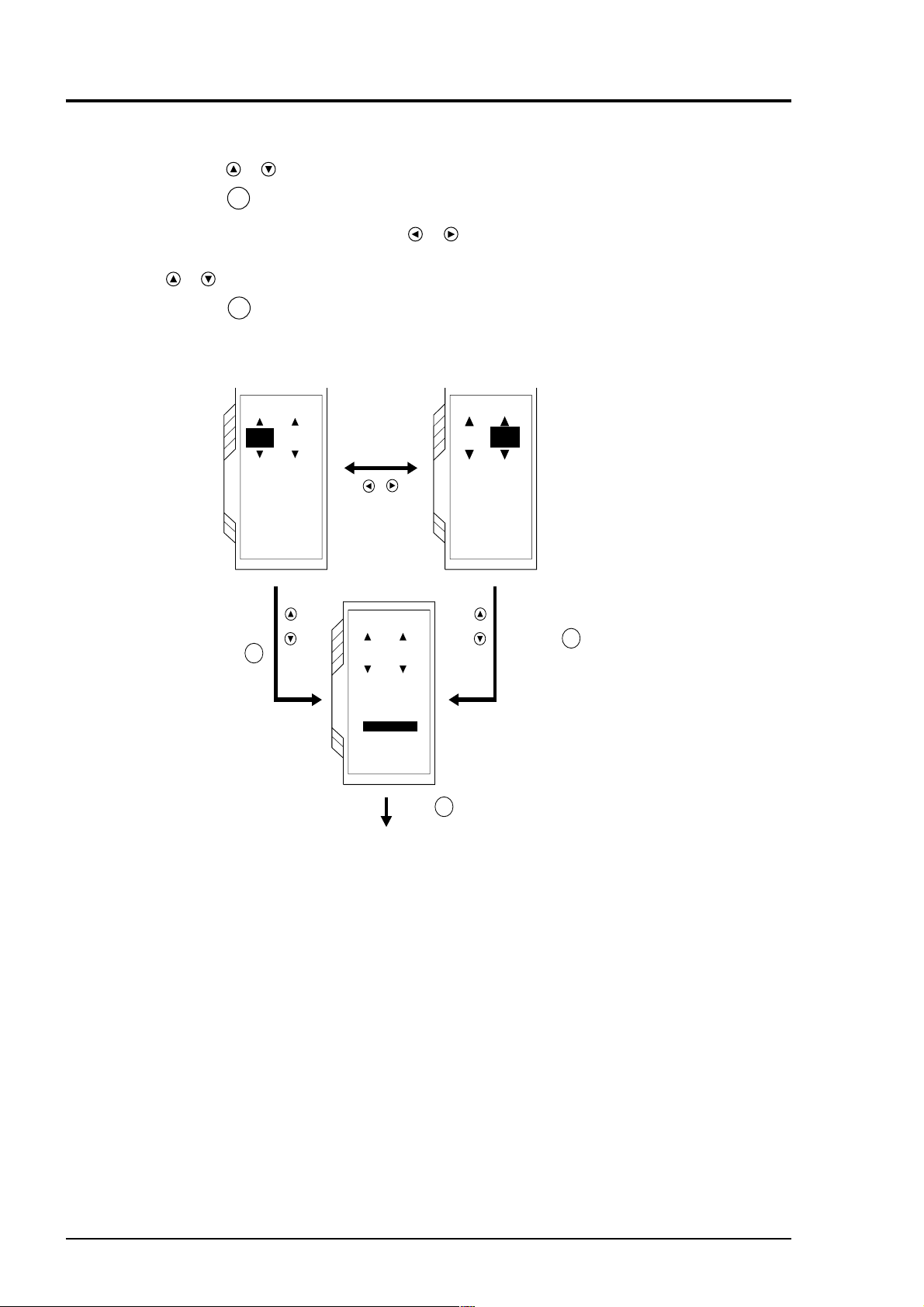
(6) ADJUST: when adjusting output circuit (prepare an ammeter)
BULLETIN F-68
q Press the
Press the
w Select either 4 mA or 20 mA by the
or
key on the “ANALOG IN/OUT” page and select “ADJUST” from “OUTPUT”.
ENT
key, and the ADJUST screen is displayed, enabling you to calibrate the output circuit.
or
key. Adjust the output circuit so that outputs are
adjusted to either 4 mA (0% output calibration) or 20 mA (100% output calibration) by pressing the
or
key.
e Press the
ENT
key to set the outputs.
4mA
ADJUST
4mA
ADJUST
ANALOG
Adjust output
to 4 mA with
an ammeter
and press .
ENT
20mA
ADJUST
Transition from
4 mA to 20 mA
or vice versa.
4mA
20mA
ADJUST
ADJUST
4mA
ADJUST
ANALOG
20mA
ADJUST
Adjust output to 20mA
and press .
ENT
ADJUSTED
ANALOG
ADJUSTED
PUSH ENT KEY
ENT
Press .
9 - 22
Page 64
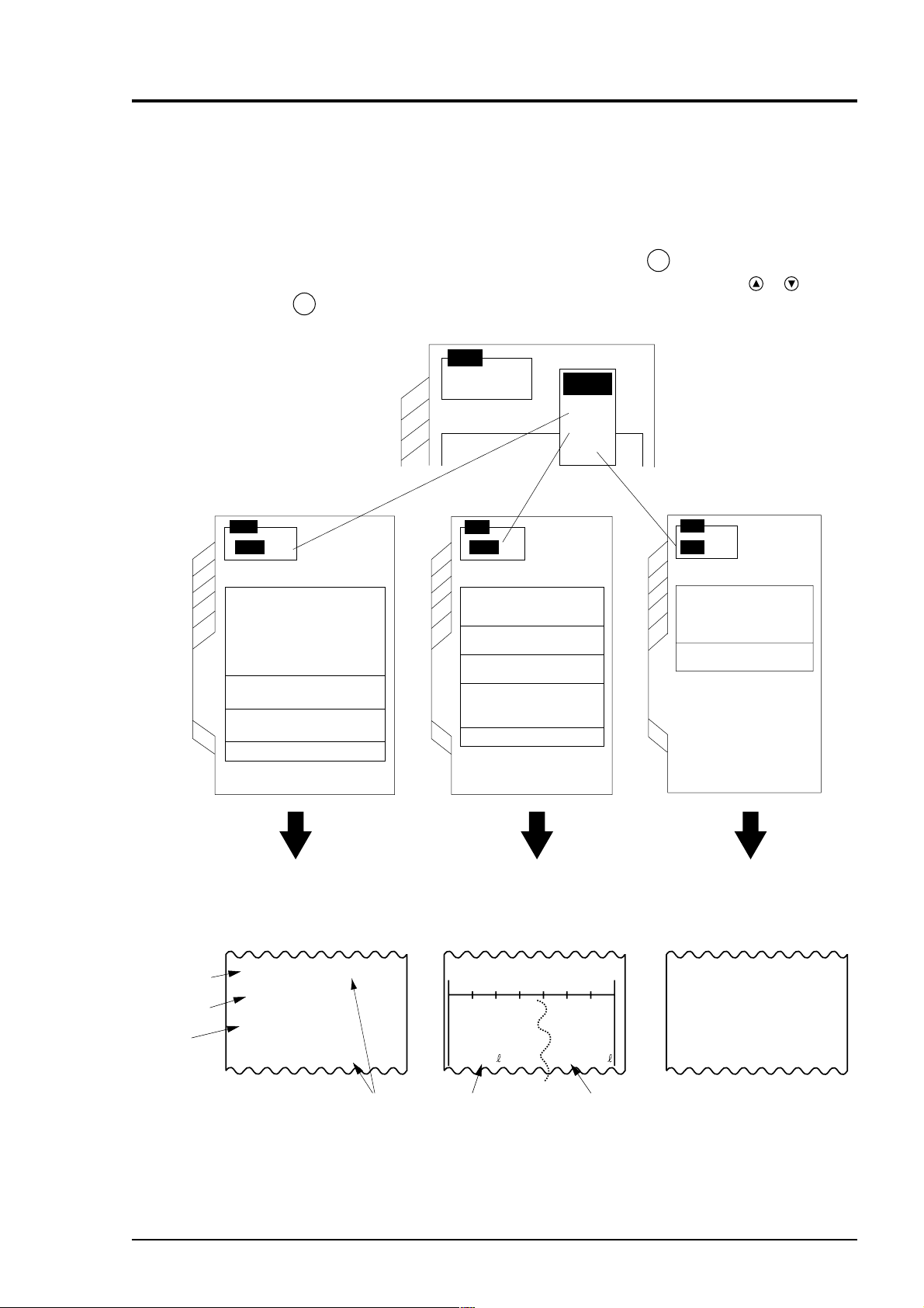
9.5 Use of printer function (PRINTER page)
BULLETIN F-68
It allows you to print measured value as well as hard copy on an optional printer. On this page, setting for
printing measured values can be performed.
9.5.1 Selection of mode
q Move the cursor to “MODE” on the PRINTER page and press the
ENT
displayed. Select any of the modes of “TEXT”, “GRAPH”, and “LIST” by the
ENT
press the
key. For the meaning of each mode, refer to an example of the following printing.
MODE
TEXT
MODE
MODE
TEXT
GRAPH
MODE
MODE
TEXT
TEXT
UNIT
TIMER MODE
PRINTER
SAMPLING PERIOD
PRINT OUT
FLOW RATE
VELOCITY
+
TOTAL
—
TOTAL
ANALOG IN OFF
OFF
OFF
OFF
TIMER
00:01
UNIT
MODE
GRAPH
UNIT
+ TOTAL
— TOTALONON
TIMER MODE
SAMPLE INTERVAL
SCALE SET
PRINTER
LEFT
RIGHT
PRINT OUT
FLOW RATE
LIST
m/s
MANUAL
00:00:01
-1.000E0
0.000E0
PRINTER
key. The “MODE” screen is
or
key and
MODE
LIST
SITE SETTING LIST OFF
SITE NAME ( 123 )
SYSTEM SETTING LIST OFF
ANALOG LIST OFF
PRINT RUN
Date and time
Selected item
Measured
status
TEXT mode
Prints data for selected unit in
industrial value.
Example of printout
95-11-27 19 : 04 : 17
5.000E-3 m/s
2.323E-3 m3/h
NORMAL
95-11-27 19 : 05 : 17
GRAPH mode
Prints data for selected unit in graph.
Example of printout Example of printout
TIME=11-27 19:06:00 / UNIT:m/s
0.000E0 1.000E0
-123456 +123456
Reverse total value Forward total valueSampling period
LIST mode
Selected list
Site setup
Site name
Outer diameter
Pipe material
Wall thickness
Lining material
123
34.00mm
Carbon steel
3.20mm
No lining
9 - 23
Page 65

9.5.2 Selection of items to print
BULLETIN F-68
(1) TEXT mode
Up to 16 items available for printing are enumerated below:
• Flow rate (12 items)
• Flow velocity
• + Total
• - Total
• Analog input
Only desired items out of 16 items are allowed to print.
One or more items are selectable simultaneously.
q Press the
or
and select “FLOW RATE”. Press the
and the FLOWRATE screen is displayed,
enabling you to select any of displayed units.
Note) Items in 9.1. 6 TOTALIZE should be set.
key on the PRINTER page
ENT
key,
MODE
TEXT
UNIT
TIMER MODE
PRINTER
SAMPLING PELIOD
PRINT OUT
FLOW RATEFLOW RATE
VELOCITY
+TOTAL
–TOTAL
ANALOG IN OFF
MANUAL
00:01
OFF
OFF
OFF
Since one or more
items can be
selected, “ON/OFF”
is not displayed.
key to select the item (one
w Press the
more items are selectable) to print and press
or
ENT
the
or
key.
e To execute printing, select “ON” and press the
ENT
key.
r When selecting the “FLOW RATE”, “TOTAL”
and “ANALOG IN” printing units, move the
cursor to any of them and press the
ENT
key.
To execute printing, select “ON” and press the
ENT
key.
MODE
TEXT
UNIT
FLOW RATEFLOW RATE
L/sL/s OFF
L/min OFF
L/h OFF
ML/d OFF
m3/s OFF
TIMER MODE
m3/min OFF
PRINTER
m3/h OFF
SAMPLING PELIOD
Mm3/d OFF
BBL/s OFF
PRINT OUT
BBL/min OFF
BBL/h OFF
MBBL/d OFF
MODE
TEXT
UNIT
VELOCITYVELOCITY
OFFOFF
ON
TIMER MODE
PRINTER
SAMPLING PERIOD
PRINT OUT
FLOW RATEFLOW RATE
VELOCITY
+TOTAL
-TOTAL
ANALOG IN OFF
MANUAL
00:01
FLOW RATE
VELOCITYVELOCITY
+TOTAL
-TOTAL
ANALOG IN OFF
MANUAL
00:01
l/s
OFF
ONON
OFF
OFF
OFF
OFF
OFF
OFF
9 - 24
Page 66

(2) GRAPH mode
BULLETIN F-68
q Press the
select “UNIT” and press the
UNIT screen is displayed, enabling you to select
the unit.
key on the PRINTER page,
or
ENT
key. The
MODE
GRAPH
w Press the
print and press the
or
key to select one of items to
ENT
key.
UNIT
+TOTAL
–TOTAL
TIMER MODE
SAMPLE INTERVAL
SCALE SET
PRINTER
LEFT
RIGHT
PRINT OUT
MODE
GRAPH
UNIT
UNIT
m/s
– TOTAL
L/s
– TOTAL
L/min
TIMER MODE
L/h
ML/d
m3/s
SAMPLE INTERVAL
m3/min
m3/h
SCALE SET
Mm3/d
PRINTER
LEFT
BBL/s
BBL/min
RIGHT
BBL/h
PRINT OUT
MBBL/d
ANALOG IN
m/s
OFF
OFF
MANUAL
00:00:01
0.000E0
0.000E0
L/min
OFF
OFF
MANUAL
00:00:01
0.000E0
0.000E0
e Turning “+TOTAL” and “-TOTAL” ON prints
integrated value in a graph. (See an example of
printing on page 9-23).
MODE
GRAPH
UNIT
+ TOTAL
+ TOTAL
– TOTAL
OFF
TIMER MODE
ON
SAMPLE INTERVAL
SCALE SET
PRINTER
LEFT
RIGHT
PRINT OUT
L/min
OFF
OFF
MANUAL
00:00:01
0.000E0
0.000E0
9 - 25
Page 67

(3) LIST mode
BULLETIN F-68
q Press the
or
key on the PRINTER page,
select any of “SITE SETTING LIST”,
“SYSTEM SETTING LIST”, and “ANALOG
ENT
ENT
key.
LIST” for printing and press the
w Select “ON” and press the
MODE
LIST
key.
SITE SETTING LIST OFF
SITE NAME ( TEST123 )
SYSTEM SETTING LIST OFF
ANALOG LIST OFF
PRINT RUN
PRINTER
MODE
LIST
SITE SETTING LIST OFF
SITE SETTING LIST
SITE NAME ( TEST123 )
OFF
SYSTEM SETTING LIST OFF
ON
ANALOG LIST OFF
PRINT RUN
PRINTER
Example of site setting list Example of system setting list Example of analog list
Site setup
Site name
Outer diameter
Pipe material
Wall thickness
Lining material
Lining thickness
Kind of fluid
Kinematic viscosity
Sensor mounting
Sensor type
Trans. voltage
TEST123
34.00mm
Carbon steel
3.20mm
No lining
0.01mm
Water
1.004E-6 m2/s
PSX2B
x4
System setup
Communication
System of units
Measure mode
Me
mory initialize
Z
Baud rate
Stop bit
Parit
9600
None
1 bit
Metric
2
No
Analog input/output
Input
Output
Input range
Range unit
Output range
Output mode
Burn-out
1.000 E2
m3/h
4.000 E1
0.8-4-20mA
Hold
9 - 26
Page 68
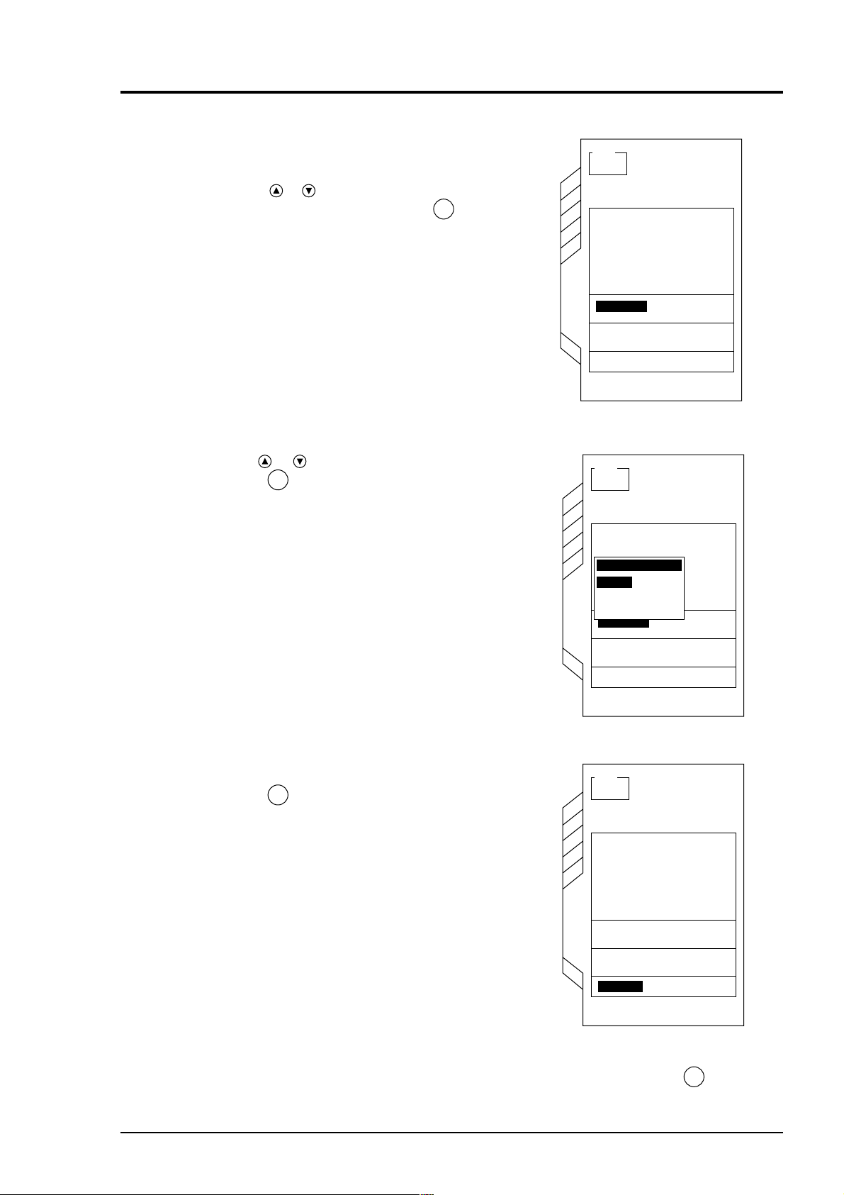
9.5.3 Setting of print time
BULLETIN F-68
(1) To print out continuously
key on the PRINTER page,
q Press the
select “TIMER MODE” and press the
The TIMER MODE screen is displayed.
w Use the
press the
or
or
key to select “MANUAL” and
ENT
key.
ENT
key.
MODE
TEXT
UNIT
TIMER MODE
PRINTER
SAMPLING PERIOD
PRINT OUT
MODE
TEXT
UNIT
TIMER MODE
MANUAL
QUICK TIMER 00:30
TIMER
TIMER MODE
PRINTER
SAMPLING PERIOD
PRINT OUT
FLOW RATE
VELOCITY
+TOTAL
–TOTAL
ANALOG IN OFF
MANUAL
00:01
FLOW RATE
VELOCITY
+TOTAL
-TOTAL
ANALOG IN OFF
MANUAL
00:01
OFF
OFF
OFF
OFF
OFF
OFF
e To select printing, select “PRINT OUT” and
ENT
press the
key.
MODE
TEXT
UNIT
TIMER MODE
PRINTER
SAMPLING PERIOD
PRINT OUT
FLOW RATE
VELOCITY
+TOTAL
–TOTAL
ANALOG IN OFF
MANUAL
00:01
OFF
OFF
OFF
To start printing, select “PRINT
ENT
OUT” and press the
key.
9 - 27
Page 69

(2) Short-time printing
BULLETIN F-68
q Press the
or
key on the PRINTER page.
Select “TIMER” and press the
Timer Mode screen is displayed.
key to select “QUICK
w Press the
or
TIMER” and press the
ENT
key.
ENT
key. The
MODE
TEXT
UNIT
TIMER MODE
PRINTER
SAMPLING PERIOD
PRINT OUT
MODE
TEXT
UNIT
TIMER MODE
MANUAL
QUICK TIMER 00:30
TIMER
TIMER MODE
PRINTER
SAMPLING PERIOD
PRINT OUT
FLOW RATE
VELOCITY
+TOTAL
–TOTAL
ANALOG IN OFF
MANUAL
00:01
FLOW RATE
VELOCITY
+TOTAL
-TOTAL
ANALOG IN OFF
MANUAL
00:01
OFF
OFF
OFF
OFF
OFF
OFF
9 - 28
e The TIME selection screen is displayed. Press
or
the
Press the
r
completed. Then, press the
key to select the printing time.
ENT
key, and the setting is now
ESC
key to
return to the previous screen.
t Select “PRINT OUT” and press the
ENT
key. Printing is continued until the selected
time passes and is stopped.
Example) Select 00:30 on the TIME selection
screen and press the
"PRINT OUT" and press the
Then, printing will be started and stopped
in 30 minutes.
ENT
key. Select
ENT
key.
MODE
TEXT
UNIT
TIMER MODE
QUICK TIMER
MANUAL
00:30
QUICK TIMER 00:30
01:00
01:30
TIMER
02:00
TIMER MODE
02:30
PRINTER
03:00
SAMPLING PELIOD
PRINT OUT
FLOW RATE
VELOCITY
+TOTAL
-TOTAL
ANALOG IN OFF
MANUAL
00:01
OFF
OFF
OFF
Page 70

(3) To print after the start and stop times are set
BULLETIN F-68
q Press the
select “TIMER MODE” and press the
or
key on the PRINTER page,
ENT
key.
The Timer Mode screen is displayed.
w Select “TIMER MODE” by pressing the
or
key and press the
ENT
key.
MODE
TEXT
UNIT
TIMER MODE
PRINTER
SAMPLING PERIOD
PRINT OUT
MODE
TEXT
UNIT
TIMER MODE
MANUAL
QUICK TIMER 00:30
TIMER
TIMER MODE
PRINTER
SAMPLING PERIOD
PRINT OUT
FLOW RATE
VELOCITY
+TOTAL
–TOTAL
ANALOG IN OFF
MANUAL
00:01
FLOW RATE
VELOCITY
+TOTAL
-TOTAL
ANALOG IN OFF
MANUAL
00:01
OFF
OFF
OFF
OFF
OFF
OFF
e The Timer Setup screen is displayed. Press the
ENT
key, and you are ready to set “START
DATE/TIME”.
MODE
TEXT
UNIT
TIMER MODE
MANUAL
TIMER
QUICK TIMER 00:30
START DATE/TIME
TIMER
END DATE/TIME
TIMER MODE
PRINTER
SAMPLING PERIOD
PRINT OUT
FLOW RATE
VELOCITY
+TOTAL
-TOTAL
ANALOG IN OFF
MANUAL
00:01
OFF
OFF
OFF
06-27 19:46
06-27 19:46
9 - 29
Page 71

r Move the digit by the
BULLETIN F-68
numeric value by the
ENT
key to set the start time.
key and enter a
or
or
key. Press the
MODE
TEXT
Example) when starting on 06-27 20: 00
(June 27, 20: 00)
t The screen is in a state of setting “END DATE/
TIME” by pressing the
key. Set the end time
in the same manner as in the “START DATE/
TIME” settings.
Example) when stopping on 06-27 23: 00
(June 27, 23: 00)
UNIT
TIMER MODE
MANUAL
TIMER
QUICK TIMER 00:30
START DATE/TIME
TIMER
END DATE/TIME
TIMER MODE
PRINTER
SAMPLING PERIOD
PRINT OUT
MODE
TEXT
UNIT
TIMER MODE
MANUAL
TIMER
QUICK TIMER 00:30
START DATE/TIME
TIMER
END DATE/TIME
TIMER MODE
PRINTER
SAMPLING PERIOD
PRINT OUT
FLOW RATE
VELOCITY
+TOTAL
-TOTAL
ANALOG IN OFF
MANUAL
00:01
FLOW RATE
VELOCITY
+TOTAL
-TOTAL
ANALOG IN OFF
MANUAL
00:01
OFF
OFF
OFF
06-27 20:00
06-27 19:46
OFF
OFF
OFF
06-27 20:00
06-27 23:00
ESC
y Press the
key 2 times to return to the screen
shown at right.
u Select “P
RINT OUT” and press the
Printing will start at the set start time and stop at
the set stop time.
ENT
key.
MODE
TEXT
UNIT
TIMER MODE
PRINTER
SAMPLING PERIOD
PRINT OUT
FLOW RATE
VELOCITY
+TOTAL
–TOTAL
ANALOG IN OFF
MANUAL
00:01
OFF
OFF
OFF
9 - 30
Page 72

9.5.4 To set printing intervals
BULLETIN F-68
q Press the
select “SAMPLING PERIOD” and press the
ENT
key. The SAMPLING PERIOD screen is
displayed.
w Move the digit by pressing the
enter a numeric value by pressing the
key. Press the
period.
Setting
In the TEXT mode: 00 : 00
In the GRAPH mode: 00 : 00 : 00
Example) When printing data in a graph every 20
minutes, set the print period to “00 : 20 : 00”.
or
key on the PRINT page,
or
ENT
key and set the sampling
Hour: Minute
Hour: Minute: Second
key, and
or
9.5.5 To set graph scale in GRAPH mode
MODE
TEXT
UNIT
TIMER MODE
PRINTER
SAMPLING PERIOD
PRINT OUT
FLOW RATE
VELOCITY
+TOTAL
—TOTAL
ANALOG IN OFF
OFF
OFF
OFF
TIMER
00:01
[This setting should be done only when the “GRAPH” mode is set.]
q Press the
or
key on the PRINT page,
select “LEFT” from “SCALE SET” and press
ENT
the
key. The screen is displayed, enabling
you to set measured values at LEFT.
or
or
key.
key and enter a
w Move the digit by the
numeric value by the
Press the
ENT
key to set measured value at
LEFT.
MODE
GRAPH
UNIT
+ TOTAL
— TOTAL
TIMER MODE
SAMPLE PERIOD
SCALE SET
PRINTER
LEFT
RIGHT
PRINT OUT
L/min
OFF
OFF
MANUAL
00:00:01
0.000E0
1.000E0
e Press the
key to set “RIGHT”.
r Set RIGHT in the same manner as in “LEFT”.
t Press the
ENT
key to return to the previous
screen.
9 - 31
Page 73

9.5.6 Printing
BULLETIN F-68
Press the
Press the
or
key to select the “PRINT OUT”.
ENT
key to start printing.
MODE
GRAPH
9.5.7 Printing stop
(1) To pause printing
q To cause printing to pause when printing, move
the cursor to “PRINT PAUSE” and press the
ENT
key. When starting printing again, move
the cursor to “CONTINUE” and press the
key.
ENT
UNIT
TIMER MODE
PRINTER
SAMPLING PERIOD
PRINT OUT
!
PRINT PAUSEPRINT PAUSE
PRINT STOP
MODE
GRAPH
UNIT
TIMER MODE
PRINTER
SAMPLING PERIOD
PRINT OUT
FLOW RATE
VELOCITY
+TOTAL
—TOTAL
ANALOG IN OFF
PRINTER
RUNNING
FLOW RATE
VELOCITY
+TOTAL
—TOTAL
ANALOG IN OFF
OFF
OFF
OFF
TIMER
00:01
OFF
OFF
OFF
TIMER
00:01
(2) To stop printing
9 - 32
q To stop printing when printing, move the cursor
ENT
to “PRINT STOP” and press the
key.
Printing is stopped.
PRINTER
!
RUNNING
PRINT PAUSEPRINT PAUSE
PRINT STOP
PRINTER
!
RUNNING
PRINT PAUSE
PRINT STOP
Page 74

9.6 System check function (SYSTEM CHECK page)
BULLETIN F-68
This function allows you to check the condition of this instrument. If an error occurs, take countermeasures according to chapter 11, “ERROR AND REMEDY”.
9.6.1 ERROR CHECK
When an error is detected on MEASURE screen
q Move the cursor to “ERROR CHECK” on the
SYSTEM CHECK page and press the
The ERROR CHECK screen is displayed.
w Select error items displayed on the MEASURE
screen by pressing the
or
key.
ENT
key.
SYSTEM CHECKSYSTEM CHECK
SYSTEM CHECKSYSTEM CHECK
ERROR CHECK
ERROR CHECKERROR CHECK
SIGNAL CHECK
SIGNAL CHECK
OUTPUT CHECKOUTPUT CHECK 75.00%
OUTPUT CHECK
VER. NO.
VER. NO.
SYSTEM CHECKSYSTEM CHECK
SYSTEM CHECK
SYSTEM CHECKSYSTEM CHECK
ERROR CHECKERROR CHECK
INSIDE COMMUNICATION FAIL
INSIDE COMMUNICATION FAIL
MEASURING MODULE FAULT
CALCULATION ERROR
PRINTER FAIL
RECEIVED SIGNAL ERROR
WINDOW SCANNING
NO RECEIVED SIGNAL
TOO STRONG RECEIVED SIGNAL
ANALOG OUTPUT ERROR
BACKUP BATTERY FAIL
SYSTEM CHECK
0.00%0.00%
e Press the
ENT
key, and the countermeasure
against error screen is displayed.
SYSTEM CHECKSYSTEM CHECK
INSIDE COMMUNICATION FAILINSIDE COMMUNICATION FAIL
Inside communication between modules has failed, so
measurements are impossible.
Turn the power off and on!
When the function will not
recover,contact the factory
SYSTEM CHECK
9 - 33
Page 75

Countermeasures against error screen
BULLETIN F-68
1 234
INSIDE COMMUNICATION FAIL
MEASURING MODULE FAULT
CALCULATION ERROR
PRINTER FAIL
SYSTEM CHECK
INSIDE COMMUNICATION FAIL
Inside communication between modules has failed, so
measurements are impossible.
Turn the power off and on!
When the function will not
recover,contact the factory
SYSTEM CHECK
56
RECEIVED SIGNAL ERROR WINDOW SCANNIN NO RECEIVED SIGNAL TOO STRONG RECEIVED
SYSTEM CHECK
MEASURING MODULE FAULT
Measuring has not acted
correctly.
Turn the power off and on!
When the function will not
recover,contact the factory.
SYSTEM CHECK
SYSTEM CHECK
CALCULATION ERROR
Calculated parameters for
flowrate measurement are not
correct.
Recheck the set data!
Turn the power off and on!
When the function will not
recover,contact the factory.
SYSTEM CHECK
SYSTEM CHECK
PRINTER FAIL
Printer unit has failed,so
it cannot start printing.
Check whether paper jam or
not!
Check if the connection to
the converter is correct.
Turn the power switches of
converter and printer unit
off and on!
When the function will not
recover,contact the factory.
SYSTEM CHECK
78
SIGNAL
SYSTEM CHECK
RECEIVED SIGNAL ERROR
The strength of received
signals is changing so frequently that measurements
are impossible!
Check if many bubbles or
solid particles are contained in measured fluid!
If so,reduce them to be
measurable,otherwise change
the mounting site of the
detector to other places.
SYSTEM CHECK
WINDOW SCANNIG
There is no signal within
the measuring window.
Therefore the measuring
window is being scanned
to search signal wave.
SYSTEM CHECK
NO RECEIVED SIGNAL
Received signals are so
poor that measurements are
impossible.
Recheck the set data,especially pipe parameters and
sensor mounting method!
Check the sensor spacing,
and the connection betwween
converter and detector!
Otherwise set the transmission voltage higher.
SYSTEM CHECK
TOO STRONG RECEIVED SIGNAL
Received signals are so
strong that measurments are
impossible.
Change the mounting method
of the detector from Z to V!
SYSTEM CHECK
9
SYSTEM CHECK
ANALOG OUTPUT ERROR
Magnitude of analog output
exceeds the scale range.
Change the scale!
SYSTEM CHECK
SYSTEM CHECK
10
BACKUP BATTERY FAILANALOG OUTPUT ERROR
SYSTEM CHECK
BACKUP BATTERY FAIL
Backup battery for set data
and logging data has failed.
Contact the factory for exchange!
Be careful that the data
will fail if you turn the
power off!
Be careful that this fail
information will disappear
if you press the ESC key!
SYSTEM CHECK
SYSTEM CHECK
SYSTEM CHECK
9 - 34
Page 76

9.6.2 SIGNAL CHECK
BULLETIN F-68
(1) To check for ultrasonic receiving signal waveform;
q Move the cursor to “SIGNAL CHECK” on the
ENT
SYSTEM CHECK page and press the
key,
and the Receiving Signal Waveform screen is
displayed.
w Move the cursor to “SOURCE” by pressing the
key as shown at right and press the
or
or
key to select either of waveforms
(upstream and downstream).
SYSTEM CHECKSYSTEM CHECK
SYSTEM CHECKSYSTEM CHECK
ERROR CHECK
ERROR CHECK
SIGNAL CHECK
SIGNAL CHECKSIGNAL CHECK
OUTPUT CHECKOUTPUT CHECK 75.00%
OUTPUT CHECK
VER. NO.
VER. NO.
SYSTEM CHECK
SYSTEM CHECK
Displays the sound velocity of fluid
to be measured.
Measures in real time.
SOUND SPEED 1521m/s
Receiving
waveform
e Move the cursor to “CURSOR” by pressing the
or
key as shown at right and press the
key to move the cursor to a receiving
or
signal waveform-like point.
445
SOURCE
TIME / 1DIV
SYSTEM CHECK
DATA / 1DIV
CURSOR
SOUND SPEEDSOUND SPEED 1521m/s1521m/s
SOURCE
TIME / 1DIV
SYSTEM CHECK
DATA / 1DIV
CURSORCURSOR
UP STREAM WAVE
160
5000
96
9577
UP STREAM WAVE
160
5000
272
: UPSTREAM
WAVE
: DOWN STREAM
WAVE
CURSOR
9 - 35
Page 77

r Move the cursor to “TIME/1 DIV” by pressing the
BULLETIN F-68
or
key as shown at right and enlarge the
scale of the time axis (horizontal axis) by the
key. (Magnifying power is 10, 20, 40, 80, and
160 times).
To contract the scale after enlargement, press the
key.
SOUND SPEEDSOUND SPEED 1521m/s1521m/s
9699
t Move the cursor to “DATA/1 DIV” and enlarge
the scale of the data axis (vertical axis) by the
key. (Magnifying power is 10, 100, 100, 1000,
5000 and 10000 times). To contract the scale
after enlargement, press the
key.
SOURCE
TIME / 1DIVTIME / 1DIV
SYSTEM CHECK
DATA / 1DIV
CURSOR
SOUND SPEEDSOUND SPEED 1521m/s1521m/s
UP STREAM WAVE
10
5000
272
• 10
• 20
• 40
• 80
• 160
9 - 36
SOURCE
TIME / 1 DIV
SYSTEM CHECK
DATADATA / 1DIV / 1DIV
CURSOR
UP STREAM WAVE
20
5000
272
10446
• 10
• 100
• 1000
• 5000
• 10000
Page 78

(2) Check to judge whether ultrasonic receiving signal waveform is normal or
BULLETIN F-68
not
q Normal waveform
The receiving waveform above is free of noise,
and so normal measurement is allowed.
Peak value of about
15000 to 20000
w Abnormal waveform
The above receiving waveform is not covered
within the range of the ultrasound waveform. It
is displayed as “CALCULATION ERROR” or
“RECEIVED SIGNAL ERROR”.
Check the pipe setting and sensor mounting
dimensions.
SOUND SPEEDSOUND SPEED 1521m/s1521m/s
10446
SOURCE
TIME / 1DIVTIME / 1DIV
SYSTEM CHECK
DATA / 1DIV
CURSOR
UP STREAM WAVE
20
5000
272
5000
When ultrasonic receiving signal waveform is
weakened by the effect of rust in the pipe,
abnormal waveform may result. Raise the
transmission voltage and perform measurement.
(See page 6-12).
Receiving waveform is cut off.
SOUND SPEEDSOUND SPEED 1669m/s1669m/s
-6289
SOURCE
TIME / 1DIVTIME / 1DIV
SYSTEM CHECK
DATA / 1DIV
CURSOR
UP STREAM WAVE
20
5000
112
Receiving
range
9 - 37
Page 79

9.6.3 OUTPUT CHECK
BULLETIN F-68
when performing the setting of constant current output (available for loop check or to check for the
power supply output circuit of this instrument)
q Move the cursor to “OUTPUT CHECK” on the
SYSTEM CHECK page and press the
ENT
key.
The OUTPUT CHECK screen is displayed,
enabling you to perform the constant current
output settings.
w Move the digit by the
numeric value by the
press the
ENT
key, and the constant current
or
or
key, enter a
key and then
output settings can be accomplished. (range:
-
20.0% to 120.0%)
SYSTEM CHECK
ERROR CHECK
SIGNAL CHECK
OUTPUT CHECK 0.00%
VERSION NUMBER
SYSTEM CHECK
SYSTEM CHECKSYSTEM CHECK
ERROR CHECK
SIGNAL CHECK
OUTPUT CHECK 0.00%
9.6.4 VERSION NUMBER
To check the current version of software, move the
cursor to “VERSION NUMBER” on the SYSTEM
CHECK page and press the
ENT
key.
VERSION NUMBER
SYSTEM CHECK
(Example)
VERSION NUMBER
VERSION NUMBER
PUX
Ver.5.08
9 - 38
Page 80

10. MAINTENANCE AND CHECKUP
BULLETIN F-68
(1) Cleaning of converter and detector
Wipe off contamination, dust, etc. from the keyboard and main frame of the converter unit occasionally
with soft cloth or the like. If contaminants cannot be removed by wiping with dry cloth, moisten cloth with
water, wring it adequately and wipe again.
Before accommodating the converter in the carrying case after use, wipe off grease completely.
Note) Do not use volatile agents such as benzine and paint thinner for cleaning.
(2) When instrument unused
Put the instrument in the furnished carrying case and store it at a place which meets the following
conditions.
• Not exposed to direct sunlight, rain, etc.
• Free from extremely high temperature and humidity (away from a heater)
Storage temperature: -10 to 45°C
• Absence of excessive dust and other contaminants.
(3) Replacement of memory backing battery
In normal usage, the battery has a service life of about 5 years.
When the battery has reached the end of its service life, the data stored in memory will all be lost.
For replacement, contact Dwyer Instruments.
(4) Replacement of LCD
LCD has a lifetime of 5 years or longer when used continuously. When display becomes difficult to be
read or the backlight does not come on, the LCD should be replaced with a new one.
For replacement, contact Dwyer Instruments.
(5) Replacement of built-in battery
The built-in battery can be charged up to about 500 times.
If it cannot be charged, it is an indication that the battery life is terminated and it needs to be replaced.
For replacement, be sure to use the battery specified by Dwyer Instruments.
(6) Replacement of printer roll-paper
When roll-paper is used for panel copy (hard copy), up to about 181 panels can be printed. When a red
band appears on the roll-paper, it is an indication that little paper is left for printing. Replace with new one
(OEM or equivalent: SEIKO Instruments; P/N: TP080-20LJ1).
10 - 1
Page 81

11. ERROR AND REMEDY
BULLETIN F-68
11.1 Error in LCD Display
If an error occurs, refer to Table below.
Status
No display appears.
Irrational display
Display is not clear.
Cause Remedy
• Power supply is not turned on.
• Voltage is low.
• Fuse has blown.
• LCD is abnormal.
• Connection of DC power supply
is reverse in polarity.
• Hardware error
•• Ambient temperature is high
(50° or higher)
LCD has reached the end of its
service life.
• Line voltage is low.
• LCD is abnormal.
See section 10 (4) "Replacement of LCD"
Lower the temperature.
Replace the LCD.
See section 10 (4) "Replacement of LCD"
Entire display is blackish.
11.2 Error of key
No response is made to key
input.
Any particular key does not
function or functions in a
wrong way.
• Ambient temperature is high
(50° or higher)
• Hardware error
Lower the temperature.
11 - 1
Page 82

11.3 Error in measured value
BULLETIN F-68
State
Indication of measured
value is negative (
Measured value
fluctuated widely
though flow rate is
constant.
Measured value
remains the same
though flow rate is
changing.
-
).
Cause
• Connection between the main unit
and sensors (upstream sensor and
downstream sensor) is reverse.
• Fluid is actually flowing in the (-)
direction.
• Straight pipe portion is inadequate.
• A flow disturbing factor such as
pump or valve is provided in the
vicinity.
• Pulsation is occurring actually.
• Measured value is held because ultrasonic
wave cannot be propagated into a pipe.
1. Incomplete installation
• Piping specifications are wrong.
• Sensor is mounted at the welded
part.
• Sensor mounting dimension is
wrong.
• Grease application at sensor
mounting is incomplete.
• Sensor connector is not
connected completely.
• Pipe surface is contaminated.
Remedy
Connect correctly.
Shift measurement location to
the site where 10D and 5D can
be secured on the upstream and
downstream sides.
Mount the instrument with a
clearance of 30D or more.
Extend response time through
damping setting.
After check, separate the sensor
once. Apply the grease again
and remount the sensor with a
slight shift.
11- 2
2. Problem on pipe or fluid
• When V method is used, it should
be changed to Z method.
• When sensor extension cable is
used, it should be avoided.
• If error persists, check and
eliminate the true cause as
instructed below.
Fluid is not filled.
Find the location on the same
pipe line, where fluid is filled
up and move the sensors to that
location.
Mount the sensors at the lowest
location on pipe line.
Page 83

State Cause Remedy
BULLETIN F-68
Air bubbles have entered.
In case measurement is normal
with water flow stopped, entrance
of air bubbles is the cause of this
error.
When the sensor is mounted just
after a valve, cavitation will occur
to cause the same effect as
entrance of air bubbles.
Turbidity is high.
Turbidity is higher than those of
sewage and return sludge.
Because of an old pipe, scale has
stuck to the inside.
Lining is thick.
Because of mortar lining or the
like, thickness is a few ten mm or
more.
Eliminate entrance of air
bubbles.
• Raise the level of pump well.
• Confirm the shaft seal of
pump.
• Retighten the flange of
negative pressure piping.
• Prevent fluid from rushing
into pump well.
Move the sensor to the location
where air bubbles have not
entered.
• To the inlet side of pump
• To the upstream side of
valve
• Change the sensor mounting
method from V to Z.
• Move the sensor to the
location on the same line,
where the outer diameter of
pipe is smaller.
• Move to a different place or
different pipe.
• Raise the voltage for
transmission (refer to p.6-12).
Lining is peeled.
There is a gap between lining and
piping.
Sensor is mounted at a bent pipe
or tapered pipe.
3. Influence by external noise
• There is a radio broadcasting
station in the vicinity.
• Measurement has been
conducted near heavy traffic.
• Sensor mounting is incomplete.
• Mounting dimension is
improper.
• Sensor is not in contact with
pipe.
4. Hardware error
Try measurement with the
optional large size sensor.
Contact
Mount to a straight pipe.
• Minimize the cable between
main unit and sensors.
Mount the sensors in parallel
with the pipe following the
correct mounting dimension.
Bring the sensor in close contact
with the pipe.
Contact
Dwyer Instruments
Dwyer Instruments
11 - 3
Page 84

State
BULLETIN F-68
Cause Remedy
Measured value is not
zero though water flow
has stopped.
Measured value has an
error.
• Water is subjected to convection in
a pipe.
• Zero adjustment has been
performed.
• When water flow stops, pipe is not
filled up with water or becomes
empty.
• Input piping specifications are
different from actual ones.
• Because of an old pipe, scale has
stuck.
The length of straight pipe portion
is inadequate.
10D and 5D are required at least
on the upstream and downstream
sides.
Flow disturbing element should
not be present within 30D on
upstream side.
Pump, valve, flow joining pipe or
the like is unallowable.
Normal
• Perform zero adjustment
again after making sure water
flow has stopped completely.
• The measured value, just
when ultrasonic wave cannot
be propagated, is held.
Normal
• A difference of 1% in inner
diameter causes an error of
about 3%.
• Input specifications correctly.
• Input scale as lining.
Select a different location of
sensor mounting (move the upstream side of a flow disturbing
element).
• Mount the sensor at different
angles with respect to the
cross section of pipe to find
the location where mean value
is obtainable. The mount the
sensor at that location.
11- 4
• Pipe is not filled with water or
mud and sand have precipitated.
Precipitation is more when the
cross section of pipe has a
smaller area.
Shift the sensor to the vertical
portion of pipe.
Page 85

11.4 Error in analog output
BULLETIN F-68
State
Output remains at 4mA
though indication value
is other than 0.
Output is 0mA.
Output is not 4mA
when indication value
is 0.
Output rises beyond
20mA.
Analog output remains
the same despite
change in indication
value.
Indication value does
not match analog output.
Output remains the
same even after
calibration of analog
output.
Cause
Analog span setting has not been
made.
Cable is broken.
The zero point of analog output is not
adjusted properly.
Indication value is larger than analog
span value.
Span is deviated.
Output load is larger than 1kΩ.
• Zero point and span of analog output
are deviated.
• Hardware error
Remedy
Set the span.
Otherwise, output remains at
4mA.
Repair
Calibrate analog output.
Overshoot
Set analog span again.
Calibrate analog output.
Permissible load is 1kΩ.
Reduce the load to less than 1kΩ.
Calibrate analog output.
Contact
Dwyer Instruments
11.5 Display of error
State
"BACKUP BATTERY
FAIL" is displayed on
measurement panel.
"INSIDE
COMMUNICATION
FAIL" is displayed on
the measurement panel.
Memory data are all cleared.
• Hardware error
Cause
Remedy
Select the error check item
"BACKUP BATTERY FAIL"
using the system check page to
display the data of processing the
error, and then perform the
following operation on the
measurement panel.
• When "BACKUP BATTERY
FAIL" is released, set
measurement conditions.
• When "BACKUP BATTERY
FAIL" is not released, the
memory backup battery needs to
be replaced.
Contact Dwyer Instruments
Contact
Dwyer Instruments.
For other errors, refer to the “ERROR CHECK” screen (9.6.1, “ERROR CHECK”).
11 - 5
Page 86

12.
BULLETIN F-68
SPECIFICATIONS FOR SERIAL TRANSMISSION (RS-232C)
(1) General specifications
Communication system : Half-duplex
Synchronizing system : Start-stop synchronizing
Transmission speed : 300 / 600 / 1200 / 2400 / 4800 / 9600 bps (selectable)
Parity : Even/odd number / None (selectable)
Data length : 8 bits
Stop bit : 1 bit / 2 bits (selectable)
Data code : ASCII
Insulation : Non-insulation between transmission line and converter (see chapter 12 (3)).
(2) Interface specifications
Electric characteristic : Based on EIA RS-232C
Connection signal :
Pin No. Signal name Meaning Signal direction
2 RxD Receive data Input
3 TxD Send data Output
4 DTR Data terminal relay (Not used)
5 GND Signal ground
6 DSR Data set ready (Not used)
7 RTS Request to send (Not used)
8 CTS Clear to send (Not used)
Cable length : 15m or less
Connector : D-SUB, 9-pin plug
Connection : 1:1 connection
(3) Composition
PUX Meter Host computer
Non-isolation
RxD TxD
TxD
DTR DTR
GND
DSR
RTS RTS
CTS
Transmission cable
15m
RxD
GND
DSR
CTS
12 - 1
Page 87

(4) Setting
BULLETIN F-68
Transmission speed, parity and stop bit should be set prior to transmission.
Set values before setting.
Transmission speed : 300 bps
Parity : None
Stop bit : 1 bit
[Note] After setting, the set data in memory are backed up by built-in battery.
(5) Communication control
q Method
Transmission of data with flow trasnmitter is made according to request command from host computer.
When a command is received from host computer, the data corresponding to the command is
transmitted from Portaflow to the host computer.
w Commands
Commands with ASCII code are transmitted from host computer to flow transmitter.
The last code of 1 command is carriage return (0DH).
[Portaflow RS-232C Transmission Command Table]
Real time transmission
Command
DQ01 [CR] Instantaneous flow (L/s or gal/s)
DQ02 [CR] Instantaneous flow (L/min or gal/min)
DQ03 [CR] Instantaneous flow (L/h or gal/h)
DQ04 [CR] Instantaneous flow (ML/d or Mgal/d)
DQ05 [CR] Instantaneous flow (m
DQ06 [CR] Instantaneous flow (m
DQ07 [CR] Instantaneous flow (m
DQ08 [CR] Instantaneous flow (Mm
Data Data format (example)
1.000E + 3 L/s [CR] [CR]
1.000E + 3 L/min [CR] [CR]
1.000E + 3 L/h [CR] [CR]
3
/s or ft3/s) 1.000E + 3 m3/s [CR] [CR]
3
/min or ft3/min) 1.000E + 3 m3/min [CR] [CR]
3
/h or ft3/h) 1.000E + 3 m2/h [CR] [CR]
3
/d or Mft3/d) 1.000E + 3 Mm3/d [CR] [CR]
1.000E + 3 ML/d [CR] [CR]
DQ09 [CR] Instantaneous flow (BBL/s) 1.000E + 3 BBL/s [CR] [CR]
DQ10 [CR] Instantaneous flow (BBL/min)
DQ11 [CR] Instantaneous flow (BBL/h)
DQ12 [CR] Instantaneous flow (MBBL/d)
DV [CR] Instantaneous flow (m/s or ft/s)
1.000E + 3 BBL/min [CR] [CR]
1.000E + 3 BBL/h [CR] [CR]
1.000E + 3 MBBL/d [CR] [CR]
32.00E + 1 m/s [CR] [CR]
DI+ [CR] Normal direction integration flow + TOTAL 1234567 mL [CR] [CR]
DI- [CR] Reverse direction integration flow - TOTAL 0000123 mL [CR] [CR]
DAO [CR] Analog output
DAI [CR] Analog input
1.000E + 2 Analog Out [CR] [CR]
1.000E + 2 Analog In [CR] [CR]
DC [CR] Status NORMAL [CR] [CR]
(output of status comment of up to 20 characters)
DT [CR] Time 95 - 01 - 05 12 : 00 [CR] [CR]
: space
Space for head of flow rate/velocity ( ) shows (-) at reverse flow.
12 - 2
Page 88

Data logger transmission
BULLETIN F-68
Command Data
Output of logger file data of the
number designated by command
LF01 [CR]
to
LF20 [CR]
Output of logger data of the
number designated by command
LD01 [CR]
to
LD20 [CR]
Data format (example)
No.XX [CR]
LOG NAME : XX XX [CR]
START : 01 - 23 23 : 34 [CR]
END :01-24 23 : 12 [CR]
INTERVAL: 01: 00:00 [CR] [CR]
Data not stored:
EMPTY [CR] [CR]
Logger sampling:
DATA LOGGER SAMPLING [CR] [CR]
No.XX [CR]
LOG NAME : XX XX [CR]
START : 01 - 23 23 : 34 [CR]
END :01-24 23 : 34 [CR]
INTERVAL: 01: 00:00 [CR] [CR]
[CR]
01 - 23 23: 34 : 00 [CR]
32.00E + 1 m/s [CR]
1.000E + 3 m3/h [CR]
NORMAL [CR] [CR]
01 - 23 00 : 34 : 00 [CR]
32.00E + 1 m/s [CR]
1.000E + 3 m3/h [CR]
NORMAL [CR] [CR]
...
...
01 - 24 23 : 34 : 00 [CR]
32.00E + 1 m/s [CR]
1.000E + 3 m3/h [CR]
NORMAL [CR] [CR]
Note) Data are outputted till the end of it.
12 - 3
Page 89

13. HOW TO USE PRINTER
BULLETIN F-68
13.1 How to connect printer
q Turn off the power supply of main unit.
w Detach the top cover of main unit.
e Attach the printer.
Connect the power cord and hook up the printer to the main unit with the connector.
Connector
r Fix the printer by tightening the screw (at 2 points) to complete the connection.
t Turn ON the power supply of main unit, and then that of the printer.
y To feed a paper, press printer FEED key.
FEED KEY
Power supply for printer
ON/OFF SW
Power cord
13 - 1
Page 90
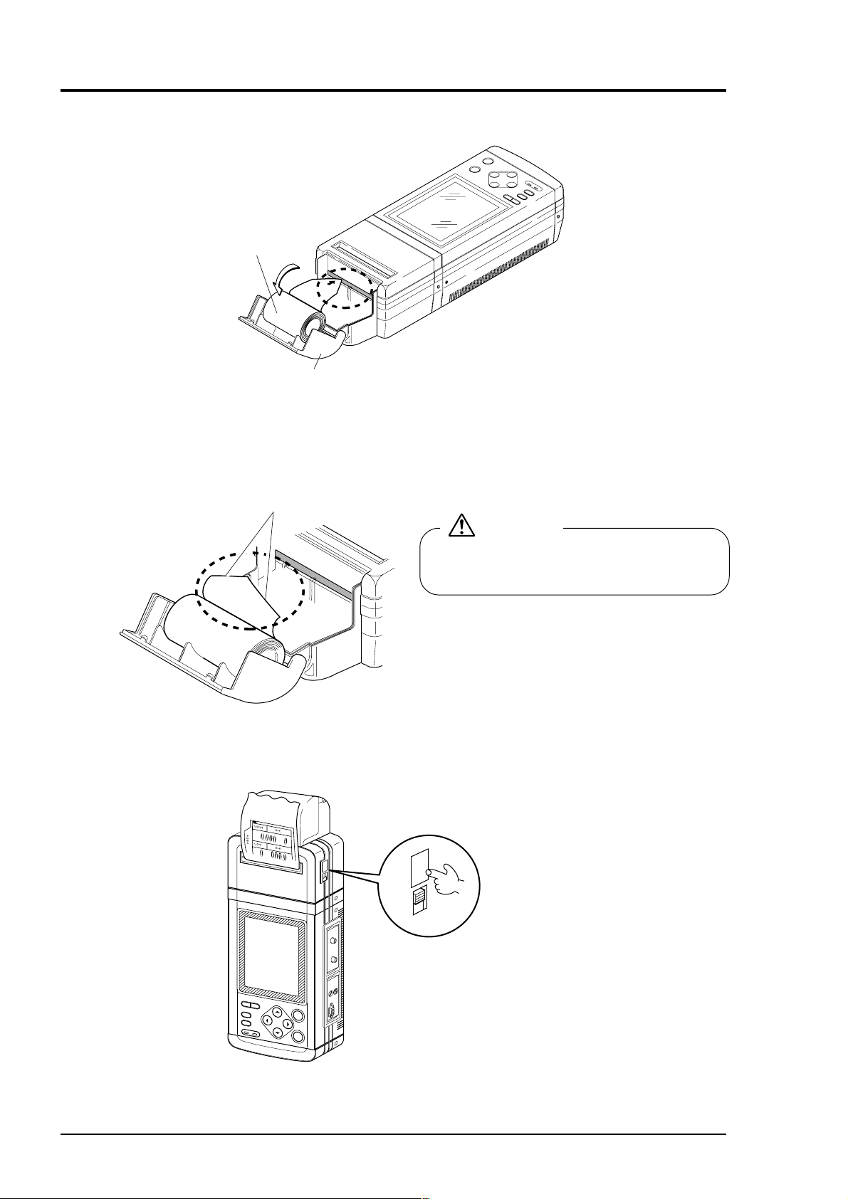
13.2 How to load printer roll sheet
BULLETIN F-68
q Open the cover and load a roll sheet
Roll sheet
Cover
w Insert the edge of roll paper into the head assembly.
The edge should be cut in a triangle for ease of insertion.
Cut in triangle
CAUTION
Don’t pull the sheet oppositely in the FEED
direction, or printer trouble may result.
e Pull the roll sheet appearing at the printer outlet or feed the roller sheet by using the printer FEED key.
M
3
/h
x
1
0
m
/s
x
1
0
FEED
FEED
ON
OFF
A sheet is only
fed by one line
every time the
FEED key is
pressed.
13 - 2
O
N
O
F
F
L
IG
H
T
P
R
IN
T
P
R
T
O
V
E
R
DC IN
E
N
T
E
S
C
Page 91

14. REPLACEMENT OF BUILT-IN BATTERY
BULLETIN F-68
q Remove 2 round countersunk screws (M3 × 5) and remove the cover from the main unit.
w Remove the battery connector, pull the battery out of the main unit, and replace it with a new one.
Main unit
Battery
Cover
Connector
Round countersunk screw
M3 × 5
14 - 1
Page 92

15. APPENDIX
BULLETIN F-68
15.1 Piping data
qq
q Stainless steel pipe for pipe arrangement(JIS G3459-1997)
qq
Note) For outer diameter and thickness of pipes, enter actual size.
20S
(mm)
Nominal thickness
Schedule
40
Thickness
(mm)
Schedule
80
Thickness
(mm)
Schedule
120
Thickness
(mm)
11.1
12.7
14.3
18.2
21.4
25.4
27.8
30.9
38.1
Schedule
160
Thickness
(mm)
Nominal
diameter
(mm)
AB
15 21.7 1.65 2.1 2.5 2.8 3.7 4.7
20 27.2 1.65 2.1 2.5 2.9 3.9 5.5
25 34.0 1.65 2.8 3.0 3.4 4.5 6.4
32 42.7 1.65 2.8 3.0 3.6 4.9 6.4
40 48.6 1.65 2.8 3.0 3.7 5.1 7.1
50 60.5 1.65 2.8 3.5 3.9 5.5 8.7
65 76.3 2.1 3.0 3.5 5.2 7.0 9.5
80 89.1 2.1 3.0 4.0 5.5 7.6 11.1
90 101.6 2.1 3.0 4.0 5.7 8.1 12.7
100 114.3 2.1 3.0 4.0 6.0 8.6 13.5
125 139.8 2.8 3.4 5.0 6.6 9.5 15.9
150 165.2 2.8 3.4 5.0 7.1 11.0 18.2
200 216.3 2.8 4.0 6.5 8.2 12.7 23.0
250 267.4 3.4 4.0 6.5 9.3 15.1 28.6
300 12 318.5 4.0 4.5 6.5 10.3 17.4 33.3
350 14 355.6 11.1 19.0 35.7
400 16 406.4 12.7 21.4 40.5
450 18 457.2 14.3 23.8 45.2 34.9
500 20 508.0 15.1 26.2 50.0
550 22 558.8 15.9 28.6 54.0 41.3
600 24 609.6 17.5 31.0 59.5 46.0
650 26 660.4 18.9 34.0 64.2 49.1
1
1
1
2
2
3
3
4
5
6
8
10
1
3
1
1
1
1
Outer
diameter
(mm)
2
4
4
2
2
2
Schedule
5S
Thickness
(mm)
Schedule
10S
Thickness
(mm)
Schedule
Thickness
ww
w Polyethylene double-layer pipe for city
ww
water (JIS K6762-1982)
Nominal
diameter
(mm)
rr
r Polyethylene pipe for general use
rr
Outer
diameter
13 21.5 3.5 2.5
20 27.0 4.0 3.0
25 34.0 5.0 3.5
30 42.0 5.5 4.0
40 48.0 6.5 4.5
50 60.0 8.0 5.0
Ist type (Soft pipe) 2nd type (Hard pipe)
(mm)
Thickness
(mm)
Thickness
(mm)
(JIS K6761-1998)
Nominal
diameter
(mm)
Outer
diameter
13 21.5 2.7 2.4
20 27.0 3.0 2.4
25 34.0 3.0 2.6
30 42.0 3.5 2.8
40 48.0 3.5 3.0
50 60.0 4.0 3.5
65 76.0 5.0 4.0
75 89.0 5.5 5.0
100 114 6.0 5.5
125 140 6.5 6.5
150 165 7.0 7.0
200 216 8.0 8.0
250 267 9.0 9.0
300 318 10.0 10.0
Ist type (Soft pipe) 2nd type (Hard pipe)
(mm)
Thickness
(mm)
Thickness
(mm)
ee
e Galvanized steel pipe for city water
ee
SGPW (JIS G3442-1997)
4
2
2
2
Outer
diameter
(mm)
76.3
89.1
101.6
114.3
139.8
165.2
216.3
267.4
318.5
Thickness
(mm)
4.2
4.2
4.2
4.5
4.5
5.0
5.8
6.6
6.9
Nominal
15 21.7 2.8
20 27.2 2.8
25 34.0 3.2
32 42.7 3.5
40 48.6 3.5
50 60.5 3.8
65
80
90
100
125
150
200
250
300
pipe
/
/
(B)(A)
1
2
3
4
1
1
1/
1
1/
2
1
2/
3
1
3/
4
5
6
8
10
12
15 - 1
Page 93

tt
BULLETIN F-68
t Asbestos cement pipe for city water (JIS A5301-1971)
tt
1st type
Outer diameter
of connected
portion (mm)
Thickness
of connected
portion (mm)
Nominal
diameter
(mm)
100 12 124 10 120
125 14 153 11 147
150 16 182 12 174
200 21 242 15 230
250 23 296 19 288
300 26 352 22 344
350 30 410 25 400
400 35 470 29 458
450 39 528 32 514
500 43 586 35 570
600 52 704 42 684
700
800
900
1000
1100
1200
1300
1500
Thickness
of connected
portion (mm)
50 10 70
75 10 95
2nd type 3rd type 4th type
Outer diameter
of connected
portion (mm)
49
56
798
912
Thickness
of connected
portion (mm)
9 118
9.5 144
10 170
13 226
15.5 281
18
20.5
23
26
28.5
34
39
44
49
54
59
65
73
81
Outer diameter
of connected
portion (mm)
336
391
446
502
557
668
778
888
998
1108
1218
1330
1496
1662
Thickness
of connected
portion (mm)
11
12
14
16
18
20
22
26
30
34
38
42
46
50
57
63
Outer diameter
of connected
portion (mm)
222
274
328
382
436
490
544
652
760
868
976
1084
1192
1300
1464
1626
yy
y Size of centrifugal sand cast iron pipe
yy
(JIS G5522)
Nominal
diameter
D
75
100
125
150
150
200
250
300
350
400
450
500
600
700
800
900
High
pressure
pipe
9.0
9.0
9.0
9.5
9.5
10.0
10.8
11.4
12.0
12.8
13.4
14.0
Pipe thickness T
Nominal
pressure
pipe
7.5
7.5
7.8
8.0
8.0
8.8
9.5
10.0
10.8
11.5
12.0
12.8
14.2
15.5
16.8
18.2
Low
pressure
pipe
7.5
7.5
8.0
8.4
9.0
9.4
10.0
10.4
11.0
11.8
12.8
13.8
14.8
Actual
outer
diameter
2
D
93.0
118.0
143.0
169.0
169.0
220.0
271.6
322.8
374.0
425.6
476.8
528.0
630.8
733.0
836.0
939.0
uu
u Rigid PVC pipe for city water
uu
(JIS K6742-1999)
Nominaldiameter
13 18.0 2.5
20 26.0 3.0
25 32.0 3.5
30 38.0 3.5
40 48.0 4.0
50 60.0 4.5
75
100
150
Outer diameter
89.0
114.0
165.0
Thickness of pipe
5.9
7.1
9.6
15 - 2
Page 94

ii
BULLETIN F-68
i Vertical cast iron pipe (JIS G5521)
ii
oo
o Hard vinyl chloride pipe (JIS K6741-1999)
oo
Thickness
Nominalpipe
D
75
100
150
200
250
300
350
400
450
500
600
700
800
900
1000
1100
1200
1350
1500
!!
00
!
0 Carbon steel pipe for pipe arrangement
!!
00
pressurepipe
Nominal
10.0
10.8
11.4
12.0
12.8
13.4
14.0
15.4
16.5
18.0
19.5
22.0
23.5
25.0
27.5
30.0
9.0
9.0
9.5
T
Lowpressure
pipe
9.0
9.4
9.8
10.2
10.6
11.0
11.5
12.0
13.0
13.8
14.8
15.5
Actualouter
diameterD
93.0
118.0
169.0
220.0
271.6
322.8
374.0
425.6
476.8
528.0
630.8
733.0
836.0
939.0
1041.0
1144.0
1246.0
1400.0
1554.0
(JIS G3452-1997)
Nominalpipe
(A)
15 21.7 2.8
20 27.2 2.8
25 34.0 3.2
32 42.7 3.5
40 48.6 3.5
50 60.5 3.8
65
80
90
100
125
150
175 190.7 5.3
200
225 241.8 6.2
250
300
350 355.6 7.9
400 406.4 7.9
450 457.2 7.9
500 508.0 7.9
(B)
1
/
3
/
1
1/
1/
2
2/
3
3/
4
5
6
7
8
9
10
12
14
16
18
20
2
4
1
4
1
2
1
2
1
2
Outer
diameter
(mm)
76.3
89.1
101.6
114.3
139.8
165.2
216.3
267.4
318.5
Thickness
(mm)
4.2
4.2
4.2
4.5
4.5
5.0
5.8
6.6
6.9
Section
1
Nominal
diameter (mm)
13 18 2.2
16 22 2.7
20 26 2.7
25 32 3.1
30 38 3.1
40 48 3.6 48
50 60 4.1 60
65 76 4.1 76
75 89 5.5 89
100 114 6.6 114
125 140 7.0 140
150 165 8.9 165
200 216 10.3 216
250 267 12.7 267
300 318 15.1 318
350 370
400 420
450 470
500 520
600 630
700 732
800 835
Outer
diameter
VP
Thickness
Outer
diameter
VU
Thickness
1.8
1.8
2.2
2.7
3.1
4.1
5.1
6.5
7.8
9.2
10.5
11.8
13.2
14.6
17.8
21.0
23.9
!!
11
!
1 Dimensions of centrifugal mold cast
!!
11
iron pipe (JIS 5523-1977)
Nominal
diameter
(mm)
75
100
125
150
200
250
300
ThicknessofpipeT
High
pressurepipe
9.0
9.0
9.0
9.5
10.0
10.8
11.4
Nominal
pressurepipe
7.5
7.5
7.8
8.0
8.8
9.5
10.0
Actualouter
diameter
1
D
93.0
118.0
143.0
169.0
220.0
271.6
322.8
!!
22
!
2 Cast iron pipe for waste water
!!
22
(JIS G5525-1975)
Nominal
diameter
50
65
75
100
125
150
200
Thickness
ofpipe
T
6.0
6.0
6.0
6.0
6.0
6.0
7.0
Actualinner
diameter
1
D
50
65
74
100
125
150
200
Actualouter
diameter
2
D
62
77
87
112
137
162
214
15 - 3
Page 95

!3!3
BULLETIN F-68
!3 Steel pipe coated for city water STW (JIS G3443-1987)
!3!3
kinds of symbol
STW 41
Nominal
diameter
A
80 89.1
100 114.3
125 139.8
150 165.2
200 216.3
250 267.4
300 318.5
350 355.6 6.0
400 406.4 6.0
450 457.2 6.0
500 508.0 6.0
600 609.6 6.0
700 711.2
800 812.8
900 914.4
1000 1016.0
1100 1117.6 10.0 8.0
1200 1219.2 11.0 9.0
1350 1371.6 12.0 10.0
1500 1524.0 14.0 11.0
1600 1625.6 15.0 12.0
1650 1676.4 15.0 12.0
1800 1828.8 16.0 13.0
1900 1930.4 17.0 14.0
2000 2032.0 18.0 15.0
2100 2133.6 19.0 16.0
2200 2235.2 20.0 16.0 20.0 16.0
2300 2336.8
2400 2438.4
2500 2540.0
2600 2641.6
2700 2743.2
2800 2844.8
2900 2946.4
3000 3048.0
Outer
diameter
mm
STW 30 STW 38
ThicknessmmThicknessmmThicknessmmThicknessmmThicknessmmThicknessmmThicknessmmThickness
4.2
4.5
4.5
5.0
5.8
6.6
6.9
4.5
4.9
5.1
5.5
6.4
6.4
6.4
Nominal thickness
AB
7.0 6.0
8.0 7.0
8.0 7.0
9.0 8.0
21.0 17.0
22.0 18.0
23.0 18.0
24.0 19.0
25.0 20.0
26.0 21.0
27.0 21.0
29.0 22.0
STW 290 STW 370
4.2
4.5
4.5
5.0
5.8
6.6
6.9
Kinds of symbol
4.5
4.9
5.1
5.5
6.4
6.4
6.4
STW 400
Nominal thickness
AB
6.0
6.0
6.0
6.0
6.0
7.0 6.0
8.0 7.0
8.0 7.0
9.0 8.0
10.0 8.0
11.0 9.0
12.0 10.0
14.0 11.0
15.0 12.0
15.0 12.0
16.0 13.0
17.0 14.0
18.0 15.0
19.0 16.0
21.0 17.0
22.0 18.0
23.0 18.0
24.0 19.0
25.0 20.0
26.0 21.0
27.0 21.0
29.0 22.0
mm
15 - 4
!!
44
!
4 Ductile cast iron pipe (JIS G5526-1998)
!!
44
Nominal
diameter
DD
75
100
150
200
250
300
350
400
450
500
Thickness
of pipe
T
1st type pipe
7.5
7.5
7.5
7.5
7.5
7.5
7.5
8.5
9.0
9.5
Actual outer
diameter
1
93.0
118.0
169.0
220.0
271.6
332.8
374.0
425.6
476.8
528.0
Nominal
diameter
600
700
800
900
1000
1100
1200
1350
1500
Thickness
of pipe
DD
T
1st type pipe
11.0
12.0
13.5
15.0
16.5
18.0
19.5
21.5
23.5
Actual outer
diameter
1
630.8
733.0
836.0
939.0
1041.0
1144.0
1246.0
1400.0
1554.0
Page 96

!!
BULLETIN F-68
55
!
5 Ductile iron specials
!!
55
(JIS G5527-1998)
!6!6
!6 Arc welded big diameter stainless steel pipe for pipe
!6!6
arrangement (JIS G3468-1994)
Nominal
diameter (mm)
75 8.5
100 8.5
150 9.0
200 11.0
250 12.0
300 12.5
350 13.0
400 14.0
450 14.5
500 15.0
600 16.0
700 17.0
800 18.0
900 19.0
1000 20.0
1100 21.0
1200 22.0
1350 24.0
1500 26.0
1600 27.5
1650 28.0
1800 30.0
2000 32.0
2100 33.0
2200 34.0
2400 36.0
Thickness of
pipe (mm)
Nominal
diameter
AB
150
200
250
300
350
400
450
500
550
600
650
700
750
800
850
900
1000
!7!7
!7 Hard vinyl chloride pipe for city water
!7!7
10
12
14
16
18
20
22
24
26
28
30
32
34
36
40
6
8
Outer
diameter
(mm)
165.2
216.3
267.4
318.5
355.6
406.4
457.2
508.0
558.8
609.6
660.4
711.2
762.0
812.8
863.6
914.1
1016.0
Schedule
5S
Thickness
mm
2.8
2.8
3.4
4.0
4.0
4.5
4.5
5.0
5.0
5.5
5.5
5.5
6.5
Nominal thickness
Schedule
10S
ThicknessmmThicknessmmThickness
3.4 5.0
4.0 6.5 8.2
4.0 6.5 9.3
4.5 6.5 10.3
5.0 8.0 11.1
5.0 8.0 12.7
5.0 8.0 14.3
5.5 9.5 15.1
5.5 9.5 15.1
6.5 9.5 17.5
8.0 12.7 17.5
8.0 12.7 17.5
8.0 12.7 17.5
8.0 12.7 17.5
8.0 12.7 17.5
8.0 12.7 19.1
9.5 14.3 26.2
(JIS K6742-1999)
Nominal diameter
13 18 2.5
20 26 3.0
25 32 3.5
30 38 3.5
40 48 4.0
50 60 4.5
75 89 5.9
100 114 7.1
150 165 9.6
Outer diameter
Thickness
Schedule
20S
Schedule
40S
mm
7.1
!8!8
!8 Arc welded carbon steel pipe (JIS G3457-1988)
!8!8
Nominal
diameter
(A)
350
400
450
500
550
600
650
700
750
800
850
900
1000
1100
1200
1350
1500
1600
1800
2000
(B)
14
16
18
20
22
24
26
28
30
32
34
36
40
44
48
54
60
64
72
80
Thickness
(mm)
Outer
diameter
(mm)
355.6
406.4
457.2
508.0
558.8
609.6
660.4
711.2
762.0
812.8
863.6
914.4
1016.0
1117.6
1219.2
1371.6
1524.0
1625.6
1828.8
2032.0
6.0
51.7
59.2
66.8
74.3
81.8
89.0
96.8
104
6.4 7.1 7.9 8.7 9.5 10.3 11.1 11.9 12.7 13.1 15.1 15.9
55.1
63.1
71.1
79.2
87.2
95.2
103
111
119
127
61.0
66.9
78.8
87.7
96.6
105
114
123
132
141
67.7
77.6
87.5
97.4
107
117
127
137
147
157
167
177
196
107
118
127
140
151
162
173
183
194
216
117
129
139
141
152
152
165
164
178
191
176
204
188
219
200
230
212
255
236
260
281
283 307 331 354
150
164
178
192
206
219
233
247
275
303
160
175
190
205
220
235
250
265
295
324
399
444
(Unit mass: kg/m)
171
187
203
219
235
251
258
266
275
282
291
314
324
346
357
390
378
439
426
488
473
521
587
297
312
315
332
335
352
373
392
411
432
448
472
505
532
562
591
600
631
675
711
751 791
15 - 5
Page 97

!9!9
BULLETIN F-68
!9 Velocity of sound subject to change
!9!9
temperature in water (0 to 100
°C)
@@
00
@
0 Velocity of sound and density of
@@
00
various liquids
T¡C
Vm/s T¡C Vm/s T¡C Vm/s T¡C T¡CVm/s Vm/s
0 1402.74
1 1407.71
2 1412.57
3 1417.32
4 1421.98
5 1426.50
6 1430.92
7 1435.24
8 1439.46
9 1443.58
10 1447.59
11 1451.51
12 1455.34
13
1459.07
14
1462.70
15
1466.25
16
1469.70
17
1473.07
18
1476.35
19
1479.55
20
1482.66
21
1485.69
22
1488.63
23
1491.50
24
1494.29
25
1497.00
Note) T: temperature, V: velocity of sound
26 1499.64
27 1502.20
28 1504.68
29 1507.10
30 1509.44
31 1511.71
32 1513.91
33 1516.05
34 1518.12
35 1520.12
36 1522.06
37 1523.93
38
1525.74
39
1527.49
40
1529.18
41
1530.80
42
1532.37
43
1533.88
44
1535.33
45
1536.72
46
1538.06
47
1539.34
48
1540.57
49
1541.74
50
1542.87
51 1543.93
52 1544.95
53 1545.92
54 1546.83
55 1547.70
56 1548.51
57 1549.28
58 1550.00
59 1550.68
60 1551.30
.
61 1551.88
62 1552.42
63
64
65
66
67
68
69
70
71
72
73
74
75
1552.91
1553.35
1553.76
1554.11
1554.43
1554.70
1554.93
1555.12
1555.27
1555.37
1555.44
1555.47
1555.45
76 1555.40
77 1555.31
78 1555.18
79 1555.02
80 1554.81
81 1554.57
82 1554.30
83 1553.98
84 1553.63
85 1553.25
86 1552.82
87 1552.37
88
1551.88
89
1551.35
90
1550.79
91
1550.20
92
1549.58
93
1548.92
94
1548.23
95
1547.50
96
1546.75
97
1545.96
98
1545.14
99
1544.29
100
1543.41
0.7905
1.0216
0.7135
1.1131
1.4870
1.0495
0.928
0.900
1.1053
1.5942
13.5955
1.207
1.2634
0.6260
0.654
0.81
0.803
1.
3
1190
1659
1006
1666
1001
1159
1181
1164
1388
938
1451
1473
1158
1032
1083
1324
1250
1460
Name of liquid ρg/cm
Acetone
Aniline
Alcohol
Ether
Ethylene glycol
n-octane
o-xylene
Chloroform
Chlorobenzene
Glycerin
Acetic acid
Methyl acetate
Ethyl acetate
Cyclohexane
Dithionic acid
Heavy water
Carbon tetrachloride
Mercury
Nitrobenzene
Carbon disulfide
Chloroform
n-propyl alcohol
n-pentane
n-hexane
Light oil
Transformer oil
Spindle oil
Petroleum
Gasoline
Water
Sea water
(salinity: 3.5%)
Note) T: temperature, ρ: density, V: velocity of sound
20
20
20 0.7893 1168
20
20
20 0.7021 1192
20 0.871 1360
20
20 1.1042 1289
20 1.2613 1923
20
20
20
20 0.779 1284
20 1.033 1389
20
20
20
20
20
20 2.8904 931
20 0.8045 1225
20
20
25
32.5 0.859 1425
32 0.905 1342
34 0.825 1295
34
13.5
16 1. 1510
@@
11
@
1 Velocity of sound per
@@
11
piping material
Material Vm/s
Iron
Steel
Ductile cast iron
Cast iron
Stainless steel
Copper
Lead
Aluminum
Brass
Vinylchloride
Acrylics
FRP
Mortar
Tar epoxy
Polyethylene
Teflon
Note) V: velocity of sound
3230
3206
3000
2460
3206
2260
2170
3080
2050
2640
2644
2505
2500
2505
1900
1240
@@
22
@
2 Dynamic viscosity coefficient of
@@
22
various liquids
Name of liquid
Acetone
Aniline
Ether
Ethylene glycol
Chloroform
Glycerin
Acetic acid
Methyl acetate
Ethyl acetate
Heavy water
Carbon tetrachloride
Mercury
Nitrobenzene
Carbon disulfide
n-pentane
n-hexane
Spindle oil
Gasoline
Water
Note)
T: temperature, ρ: density, V: velocity of sound
ν: kinematic viscosity
T¡C Vm/s
20
20
20
20
20
20 1.2613 1923 1188.5
20
20
20
20
20
20
20
20
20
20
32
34
13.5
ρg/cm
0.7905
1.0216
0.7135
1.1131
1.4870
1.0495
0.928
0.900
1.1053
1.5942
13.5955
1.207
1.2634
0.6260
0.654
0.905
0.803
1.
3
1190
1659
1006
1666
1001
1159
1181
1164
1388
938
1451
1473
1158
1032
1083
1324
1250
1460
-6
ν ( ×10 m /s)
0.407
1.762
0.336
21.112
0.383
1.162
0.411
0.499
1.129
0.608
0.114
1.665
0.290
0.366
0.489
15.7
0.4 to 0.5
1.004 (20¡C)
2
15 - 6
Page 98

15.2 Command tree
BULLETIN F-68
Closing and cutting
of power supply
MEASURE
SITE SETUP
LOGGER
UNIT
RESET
PARAMETER
MEMORY
PIPE PARAMETER
ZERO ADJUST
RESPONSE SET
CALIBRATION
CUT OFF
TOTALIZE
SAVE
LOAD
SITE NAME
OUTER DIAMETER
PIPE MATERIAL
WALL THICKNESS
LINING MATERIAL
LINING THICKNESS
KIND OF FLUID
SENSOR MOUNTING
TRANSMISSION VOLTAGE
MODE
RESET DATA
UNIT
SYSTEM SETUP
ANALOG IN/OUT
PRINTER
SYSTEM CHECK
CLOCK SET
COMMUNICATION
SYSTEM OF UNITS
MEASUREMENT METHOD
MEMORY INITIALIZE
TEXT
GRAPH
LIST
ERROR CHECK
SIGNAL CHECK
OUTPUT CHECK
VERSION NUMBER
UNIT
TIMER MODE
SAMPLE INTERVAL
SCALE SET
(for only graph mode)
15 - 7
Page 99

15.3 Specifications
BULLETIN F-68
Fluid conditions
• Measured fluid: Homogeneous liquids (water, sea water, oil or fluid of unknown sound velocity)
capable of ultrasonic wave propagation
• Turbidity of fluid: 10000 deg. (mg/L) or less
• State of flow: Axis-symmetric flow in pipe filled with fluid
• Fluid temperature: Small diameter sensor, –
Small sensor, [Standard] –
Large sensor, –
High-temperature sensor, –
• Velocity range: –32 to 0 to +32m/s
Piping conditions
• Pipe material: Steel, stainless steel, cast iron, vinyl-chloride, FRP, asbestos, aluminum, acrylic,
etc.
• Pipe size: Small diameter sensor,
Small sensor,
Large sensor,
High-temperature sensor,
• Lining material: None, tar epoxy, mortar, rubber or material of known sound velocity
• Straight pipe length: Upstream side, 10D or more
Downstream side, 5D or more (D: inner pipe diameter)
Refer to Japan Electric Measuring Instruments Manufactures’ Association’s standard JEMIS-032 for details.
Accuracy
Converter
• Power supply: Built-in battery or power adaptor
• Built-in battery: Special type Ni-MH battery
Continuous operation time, about 5 hours (without printer, back light OFF, without current output, transmission voltage setting × 1)
Recharging time, about 2 hours (power adaptor used)
• Power adaptor: Special type power adaptor 90 to 264V AC, 47 to 63Hz or 10 to 30V DC
• Power consumption: 12W or less
• LCD display: Full dot graphic display
240 x 320 dot (with back light)
• LED display: DC IN (green), FAST CHARGE (red)
• Key pad: 10 keys (ON, OFF,
• Power failure backup: Memory backup with lithium battery (effective term, 5 years)
• Response time: 1s or less
• Output signal: 4 to 20mA DC, 1 point (load resistance, 0 to 1kΩ)
• Input signal: 4 to 20mA DC (not isolated), 1 point
• Serial communication: RS-232C (not isolated), 1 point
Transmission speed: Max. 9600 bps
Transmission distance: Max. 15m
• Printer (option): To be mounted on top of converter
Thermal serial dot printing (8 x 256 dot)
• Ambient temperature: –10 to +55°C (without printer)
–10 to +45°C (with printer)
• Ambient humidity: 90% RH or less
• Type of enclosure: Dust-proof type (IP50 or equivalent)
40 to +100°C
40 to +80°C
φ
50 to φ400
φ
200 to φ6000
Pipe size
φ13 to φ50 or less
φ50 to φ300 or less
φ300 to φ6000
40 to +100°C
40 to +200°C
φ
13 to φ100
φ
50 to φ400
Flow velocity
2 to 32 m/s
0 to 2 m/s
2 to 32 m/s
0 to 2 m/s
1 to 32 m/s
0 to 1 m/s
(Note) Reference conditions are
based on JEMIS-032.
, , , , ESC, ENT, LIGHT, PRINT)
Accuracy
1.5% of rate
0.03m/s
1.0% of rate
0.02m/s
1.0% of rate
0.01m/s
15 - 8
Page 100

• Enclosure case: Plastic case (color: gray)
BULLETIN F-68
• Dimensions: H240 x W127 x D70mm (without printer)
H359 x W127 x D70mm (with printer)
• Mass: 1.5kg (without printer)
2.0kg (with printer)
Detector (Type: FLD)
• Mounting method: Mounting on outside of already constructed pipe
• Sensor mounting method: V or Z method
• Mounting belt /wire: Small diameter sensor, plastic cloth belt
Small sensor, plastic cloth belt
Large sensor, stainless wire
High-temperature sensor, stainless belt
• Acoustic coupler: Silicone grease
• Signal cable: Special type coaxial cable
• Connection: Converter; BNC connector
Small diameter sensor; BNC connector
Small sensor; BNC connector
Large sensor; terminal screws
High-temperature sensor; BNC connector
• Ambient temperature:–20 to +60°C
• Ambient humidity: Large sensor, 100% RH or less
Other, 90% RH or less
• Type of enclosure: Large sensor: immersion-proof type (IP67 or equivalent)
Other: drip-proof type (IP52 or equivalent)
• Material:
Kind Sensor case Mounting bracket
Small diameter Plastic Aluminum alloy + Plastic
Small type Plastic Aluminum alloy + Plastic
Large type Plastic —
High temperature 304SS Aluminum alloy + 304SS
• Dimensions/mass:
Functions
Kind Dimensions (HxWxD)
Small diameter 420 x 53 x 90mm 0.6kg
Small type 540 x 53 x 90mm 0.8kg
Large type 104 x 93 x 62mm 1.4kg
High temperature 530 x 52 x 205mm 1.7kg
Note) mass of both sensors
Mass
(Note)
• Display language: English/Japanese (Katakana)/German/French, selectable
• Instantaneous value display function:
Two of velocity, flow rate (with flow direction) and analog input, simultaneous
display
Unit: Velocity m/s
3
Flow rate L/s, L/min, L/h, ML/d, m
/s, m3/min, m3/h, Mm3/d
• Total value display function: Forward and reverse total values, simultaneous display
Unit: mL, L, m
3
, km3, Mm
3
• Clock display function: Time (year, month, day, hour, minute) display and setting
• Damping: 0 to 99s (time constant)
• Low flow cut: 0 to 1.000m/s
• Output setting function: Current output scaling, output type, burnout setting and calibration
• Communication function: Velocity, flow rate, totals, analog input, status, logging data transmission on
request
• Memory function: Site data (place, piping, fluid, sensor mounting method, type of sensor) up to 20
places and a maximum of 40000 data (time, velocity, flow rate, totals, analog
input, status) can be stored in memory.
• Waveform display function: Display of bi-directional received waveforms
• Graph display function: Display of velocity, flow rate trend graph
• Printing function: Printout of screen, fixed cycle printout (time, velocity, flow rate, totals, analog
input, status), logging data, trend graph, and waveforms by using integral printer
(option)
15 - 9
 Loading...