

Page 1

Bulletin J-24
Particu late Moni toring Sys te m s
PMT
Particulate Transmitter
PMT Series
INSTALLATION & OPERATING
MANUAL
Dwyer Instruments, Inc.
102 Indiana Highway 212
P.O. Box 373
Michigan City, IN 46361 USA
Telephone 800-872-9141
www.dwyer-inst.com
Page 2

Particulate Monitoring Systems Installation & Operati ng Manual
I. Technical Support & Return Procedure
Dwyer Instruments, Inc. provides industry leading technical support for all product lines. The
technical support department is staffed with a team of engineering professionals.
Areas of assistance provided by the Technical Support department include:
• Product Installation
• General Operation
• Application Specific
• Routine Calibration
• EPA Compliance
• Performance Upgrades and Add-On Features
To ensure the best and most efficient technical support please be prepared with the following
information prior to contacting Dwyer Instruments, Inc. If it is determined that the component must be
returned for evaluation/repair, a Return Material Authorization number will be issued. You must
include the RMA number on the packing slip and mark the outside of the shipping container.
• Company Name ________________________________________
• Product Model Number ________________________________________
• Product Serial Number ________________________________________
• Date of Installation ________________________________________
• Reason for Return ________________________________________
Dwyer Instruments Technical Support may be reached by:
Phone: (800) 872-9141
Fax: (219) 872-9057
E-Mail: tech@dwyer-inst.com
Hours of Operation: 8AM – 5PM Central Standard Time
• Any control unit or particulate sensor that was exposed to hazardous materials in a process
must be properly cleaned in accordance with OSHA standards and a Material Safety Data
Sheet (MSDS) completed before it is returned to the factory.
• All shipments returned to the factory must be sent by prepaid transportation.
• All shipments will be returned F.O.B. factory.
• Returns will not be accepted without a Return Material Authorization number.
Document No. 209-1026-E ii ©2007
Page 3
Particulate Monitoring Systems Installation & Operati ng Manual
II. Notifications
This document contains important information necessary for proper operation of the product.
It is strongly urged that all users of the product read this manual in its entirety. All instructions
should be followed properly and any questions that arise should be discussed with Dwye r
Instruments, Inc .
Any use or distribution of this document without the express consent of Dwyer Instruments,
Inc. is strictly prohibited. Any reproduction is prohibited without written permission.
In no event will Dwyer Instruments, Inc. be liable for any mistake, including lost profits, lost
savings, environmental compliance costs or other incidental or consequential damages arising
out of the use or inability to use this manual, even if advised of the possibility of such da mages,
or an y claim b y any oth er par ty.
Identifies information about practices or circumstances that can lead to personal
injury or death, property damage, or economic loss.
Warning statements help you to:
• Identify a hazard
• Avoid a hazard
• Recognize the consequences
Identifies information that is critical for successful application and
IMPORTANT
Identifies information, sections or statements in this manual that apply to
understanding of the product.
approved hazardous area systems, regulations or installation.
Document No. 209-1026-E iii ©2007
Page 4

Particulate Monitoring Systems Installation & Operati ng Manual
III. Approvals and Certifications
CE Conformant
The Electronics and Particulate Sensors conform to the appropriate country standards and
governing regulations listed below:
EN 55011/2002 Limits and methods of measurement of radio interference
characteristics of industrial, scientific and medical equipment. Group
1, Class A.
EN61000-6-2/2001 Electromagnetic compatibility – Generic immunity standard Part 6-2:
Industrial environments.
EN61000-4-2/2000 Electrostatic discharge (ESD), 4kV contact discharge, 8kV air
discharge, 4kV horizontal and vertical coupling planes.
EN61000-4-3/2002 Radiated electromagnetic fields, 10V/m, 80-1000Mhz.
AC line isolation for the Particulate Transmitter must be provided by an
external isolating DC power supply with CSA or UL marking. No power
supply is provided with or sold as an accessory.
CSA Certified
This Particulate Monitoring system is certified by the Canadian Standards Association (to
US and Canadian Standards) for use in hazardous locations as is specified below:
Hazardous Locations
Class I, Division 2 Groups A, B, C, and D
Class II, Division 2 Groups F, G
Class III
Document No. 209-1026-E
iv ©2007
Page 5

Particulate Monitoring Systems Installation & Operati ng Manual
IV. Specifications
ELECTRICAL
PARAMETER DETAIL SPECIFICATION NOTE
Measurement Units picoamperes (pA) 1 x 10 ⎯ ¹² Amp
Standard 10.0pA – 5000pA Measurement Range
Optional 5.0 and 0.5pA – 5000pA
Accuracy ± 5% of Range Full Temp Range
Operating -15F to +160F (-25C to +70C) Ambient Temperature
Range
Digital Filtering Range Ajustable 0.5 Sec – 60 Sec
4-20mA Output
Process Temperature
Range
Pressure Range Operating Full Vacuum to 10PSI Other, consult
Particle Concentration
(Approximate Guide)
Particle Velocity 300 ft/min. (91 m/min.) and Higher
Particle Size 0.3 Micron and Higher
Storage -40F to +185F (-40C to +85C)
Isolation 500VDC Process to Loop
Output
Compliance
Scale Linear or Logarithmic
pA Range 0-100, 0-500, 0-1000, 0-5000 Linear
Standard ½” NPT Mount Mounting
Optional Tri-clamp, Flange
Sensor Teflon over Stainless Materials
Body Stainless Steel
Operating
Type Painted Cast Aluminum Enclosure
Rating NEMA 4X (IP 66)
OPERATING and APPLICATION RANGE
10.0pA
5.0pA
Optional
0.5pA
Optional
Max. RLoad = (Vsupply–18V)/0.02A
(24VDC = 300Ohm Rload Max.)
0.5–500, 5–5000 Logarithmic
MECHANICAL
-40F to +250F (-40C to +120C)
-40F to +450F (-40C to +232C)
-40F to +800F (-40C to +427C) two piece
At least 10.0-5000 mg/m³
At least 0.004 to 2.0 gr/cf
At least 5.0 – 5000 mg/m³
At least 0.002 to 2.0 gr/cf
At least 0.5 to 500 mg/m³
At least 0.0002 to 0.2 gr/cf
Other, consult
factory
configuration
only
factory
Visible
Barely Visible
To Visible
Barely Visible
To Invisible
Document No. 209-1026-E
v ©2007
Page 6

Particulate Monitoring Systems Installation & Operati ng Manual
V. Installation Drawings
Drawing Number Sheets Description
225-1032 2 Installation Drawing
225-1036 1 High Temperature / High Pressure Particulate Flow Sensor
Installation Drawing
Document No. 209-1026-E
vi ©2007
Page 7

Particu late Monitoring Sys te m s Installation & Operating Manual
TABLE OF CONTENTS
Safety...............................................................................................................................................2
1.
1.1 Applicable Use.......................................................................................................................... 2
1.2 General..................................................................................................................................... 2
1.3 Hazardous Area Systems........................................................................................................... 3
2. Introduction.................................................................................................................................... 4
3. Comp onent Description.................................................................................................................. 5
3.1 One-p iece Config uration............................................................................................................ 5
3.2 Two-piece Configuration with Remote Electronics ....................................................................5
3.3 Particulate Sensor/Probe............................................................................................................ 6
3.4 Smart Transmitter Modu le.........................................................................................................6
3.5 Coaxial Cable for Particulate Sensor .......................................................................................... 6
3.6 Sensor Test Port (Non -Hazardous Areas Only) ..........................................................................6
4. Particulate Sensor Installation........................................................................................................7
4.1 Location.................................................................................................................................... 7
4.2 Mounting....................................................................................................................... ........... 8
4.3 Senso r Te mperature Considerations........................................................................................... 9
5. Control Unit Installation...............................................................................................................10
5.1 Location.................................................................................................................................. 10
6. Smart Transmitter Wiring............................................................................................................ 11
6.1 Groun ding ............................................................................................................................... 11
6.2 4-20mA Wiring....................................................................................................................... 11
6.3 Sensor Cable Installation – T wo piece config u r ation onl y......................................................... 12
7. Startup .......................................................................................................................................... 13
7.1 4-20mA Loop Ch eck...............................................................................................................13
7.2 System Zero Check .................................................................................................................14
8. Interpreting Readings and Adjusting 4-20mA Range..................................................................17
8.1 Fabric Filter (Baghouse) Applications...................................................................................... 17
8.2 Alarm Levels for Fabric Filter Applications............................................................................. 18
8.3 4-20mA Output Range Adjustment .......................................................................................... 20
8.4 Time-constant Adjustment....................................................................................................... 21
9. Routine Maintenance....................................................................................................................22
10. Troubleshooting............................................................................................................................ 23
11. Spare Parts.................................................................................................................................... 24
Documen t No. 210- 1015-F Page 1 ©2007
Page 8
Particu late Monitoring Sys te m s Installation & Operating Manual
1. Safety
1.1 Applicable Use
These particulate monitor systems ar e not designed for use as a functional safety device and do not
carry a SIL rating. The device m ust not be used as part of a safety syst em or as an input signal to a
safet y system. Th ese monitors ar e designed for general proce s s and envir onmental monitoring.
1.2 General
This apparatus is available with various agency approvals as noted in the approvals section. All
versions of this device have been designed to comply with EN 61010, safety requirements for
elec tric al equipment for measu rement, control a nd laboratory use, and are s u p plied in a safe co ndition.
Before beginning an in stallation the following safety precautions and all precaution s throughout this
manual and in the ins tallation dr awings mu st be followed.
AREA CLASSIFICATION
• Before installing any device confirm area classification requirements. Do
not install any device that is not tagged as suitable for the required area
classificati on .
• WARNING – Substitution of components may impair suitability for
Division 2 hazardous loc ations.
PROCESS AND AMBIENT CONDITIONS
• Before installing any device, confirm ambient temperature, process
temperature and process pressure requirements. Do not install any device
that is not tagged as suitable for the required temperatures and pressures.
Confirm compatibility of the wetted and non -wetted materials.
INSTALLATION PERSONNEL AND SERVICE
• Only appropriately licensed and trained professionals should perform the
mechan ical and el ectrical ins tallation.
• This device does not contain field serviceable components other than th e
line fuse. Only factory personnel can perform service on this equipment.
• For operator safety and to prevent ignition of flammable or combustible
atmospher es always disconnect power before servicing.
GROUNDING AND FUSING
• Before applying power to the instrument, you must connect the sensor
housing and remote electronics housing (two piece configuration) to a
pr ope r ear th ground. Th e se n sor hous in g is con n ect e d t o ea rth ground usi n g
the ext ernal groun d screw. Th e remot e electr onics h ousing is connect ed to
earth ground through the dedicated ground screw inside the housing.
Groundin g to the neutral conductor of a single-phase circuit is not sufficient
protection.
• Only fuses with the required current, volt age and specified type should be
used. D o n ot u s e r ep aired fuses or short-cir cu ited fuse hol d er s .
Documen t No. 210- 1015-F Page 2 ©2007
Page 9
Particu late Monitoring Sys te m s Installation & Operating Manual
REGULATORY CODES
• Installation and operation must adher e to all national and local codes.
1.3 Hazardous Area Syste ms
Systems approved for use in hazardous areas include nameplates indicating that they are suitable for
inst allation in hazard ou s areas. The nameplate lists allowable hazardous areas and T code ratings as
well as approval agen cy markings. Do n ot in stall any device that is not tagged as suitable for the
area classifica tion.
Section s or st at emen ts in thi s man ua l tha t a pply to a pproved ha zar dous ar ea syst ems or in s tall ati on s
are designated with the following symbol. Designation for use in hazardous areas does not make the
system su itable for use as a function al safety device.
HAZARDOUS AREAS
• WARNING – Substitution of components may impair suitability for
Division 2 hazardous loc ations.
• Installation mu st be in accord ance with ANS I /I S A RP1 2 .6 and Nati onal
Electric Code ANSI/NFPA 70, Article 504
• Do not connect or disconnect components unless power has been
disconnected.
• Designation for use in hazardous areas does not make the system
suit able for use as a fun ctional sa fety device.
Documen t No. 210- 1015-F Page 3 ©2007
Page 10

Particulate Monitoring Systems Installation & Operati ng Manual
2. Introduction
A Parti culate Mon itorin g System con sist s of a contr ol unit, a par ticul ate sensor and a sen sor coaxia l
cable. Applications include continuous emissions monitoring, baghouse filter leak detection and
process particulate flow monitoring. Types of particulate include both solid particulates (dusts,
powders, granulars, and pellets) and liquid particulates (mists). Various control unit models and
sensors are pr ovided to match the application an d process monitoring needs.
Principle of Operation
Particulate Monitoring Systems employ a highly reliable technology based on induction. A sensor
probe is mounted in an airflow stream such as a pipe, duct or stack (for small tubing an inline nonintr usive ring sen sor is employed). As particul ate flows near and over the sen sing element, m inute
electr ical cur rents ar e induced in th e sensor an d transfer red to th e control unit by a coa xial cable. A
microprocess or filter s and pr ocesses the signal into a normalized, absolute output that is linear to the
mass concentrat ion of particu late.
_ MASS CORRELATION
IMPORTANT
It is important to note that the above relation between instrument units (pA) and
actual mass (mg/m
appropriate model and range and for providi ng a general indic ation of the typic al
particulate levels monitored. For a true correlation between (pA) and actual
mass (mg/m
must be performed for each application and a recommended model and
detection level must be ordered. It is also important to note th at the accuracy of
such correlations is application dependent and produces the best results with
consistent particulate and process conditions. The user must follow proper
procedures and must understand the typical accuracy of such correlation
techn iques. Consult factor y for details.
3
or gr/cf) is just an approximate guide for selecting the
3
or gr/cf), a gravimetric correlation such as an isokinetic sample
Documen t No. 210- 1015-F Page 4 ©2007
Page 11
Particulate Monitoring Systems Installation & Operati ng Manual
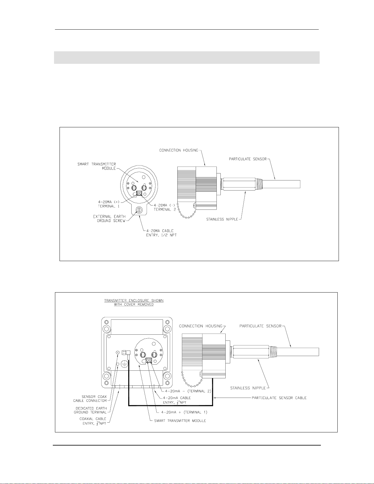
3. Component Description
One and two pi ece vers ion s of t h e par ti cula t e tran smit t er ar e ava ila ble wi th var ious pr obe lengths and
mounting configurations. The standard configuration features the smart transmitter module integrated
directly into the sensor connection housing. A two-piece configuration incorporates a separate
enclosu re for th e smar t transmitt er module, a remote sensor/probe and an in terconnect ing cable.
3.1 One-piece Configuration
(Example only, mounting and probe length variable)
3.2 Two-piece Configuration with Remote Electronics
(Example only, mounting and probe length variable)
Documen t No. 210- 1015-F Page 5 ©2007
Page 12

Particulate Monitoring Systems Installation & Operati ng Manual
3.3 Particulate Sensor/Probe
The particulate sensor consists of a stainless probe with a non-con ductive protective layer or coating,
a stainless steel nipple/moun t and the sensor housing. It is a very rugged assembly that is virtually
maint enan ce-fr ee. It does n ot req uire sp ecial ali gnment , is not a ffect ed by n orm al vibr ati on and does
not require cleaning.
3.4 Smart Transmitter Module
The smart transmitter module processes the signals induced into the pr obe, quantifyin g and digitally
filtering them in to an absolute measurement of pA (picoamps). The pA reading is tr ansmitted over a
4-20mA current loop for remote mon itoring with a control system, PLC, panel meter, recorder etc. It
is important that the 4-20mA signal be con verted back into pA at the monitor ing location to enable
evaluating the instrument output rea dings properly. Electrical isolati on is provided between the 420mA loop and the pA measurement circuitry. This isolation provides immunity to ground loop and
power supply/plc analog input card grounding possibilities.
The smart transmitter module is located directly inside the particulate sensor housing for one-piece
configurations. For two-piece configurations the smart transmitter module is located in a separate
TYPE 4X enclosure.
3.5 Coaxial Cable for Particulate Sensor
The cable that connects the particulate sensor to the control unit is a high-quality coaxial cable
specifically desi g ned for the system. Maximum length i s 30 0 ft (91m). Do not use substitute cable.
This ca bl e is requir ed for two-piece con fi g urati ons only.
3.6 Sensor Test Port (Non-Hazardous Areas Only)
The test port is not a necessary component to operate the system, but it is r ecommended. It is a
1/8”NPT x 3” pi pe nipple used to introduce particulate int o the process to perform a natural response
check. The nippl e is s cr ew ed into or welded to the pipe/ d u ct up stream of the sensor. Par ticles are
injected into the flow stream to simulate a natural increase in particle flow. It is primarily intended for
use at negative pressure locations in fabric filter outlet ducting so that wh en the cap is removed line
suction will enable par ticles to be sucked into the flow. A test port is not recommen ded for hazardous
area app lications.
Location: A test port should be in stalled in a negative pressure location. It must be located upstr eam
of the sens or s o par t i cu la t e ca n fl o w very nea r an d around th e s en s or . It sh ou l d be l oca t ed a t le a st 3 ft
(1 m) upstr eam of the sensor and it should be located on the same side of the duct as the sensor so
particles can pass very near and around the sensor. If possible locate the test port at ground level.
Mounting: Th e test port is either screwed into a 1/8 inch NPT threaded hole, or welded in position.
(Note: A foot or so of tubi n g can be con n ect ed t o th e nip pl e to ma ke it eas y to dr aw par ti cl es out of a
conta iner. Only a pinch of particu late at a time is n eed ed for a respon se ch eck.)
_ TEST PORT INSTALLATION
IMPORTANT
• Installation of a sensor test port enables checking the response to an actual
increase in particulate.
Documen t No. 210- 1015-F Page 6 ©2007
Page 13

Particulate Monitoring Systems Installation & Operati ng Manual
4. Particulate Sensor Instal lation
The following applies for both one and two piece configurations.
4.1 Location
The foll o wi ng factors should be cons idered when d etermining the sensor l oca tion:
Area Classifica t ion
Flow conditions
Ambient & Process Tem p eratures
Process Pressur e
Electrical (Faraday) shi elding
Atmospheric shielding (in the case of ducts and stacks open to atmosph er e)
Access for install at i on and service
INSTALLATION PERSONNEL
• Only appropriately licensed professionals should install this product.
• For operator safety and to prevent ignition of flammable or combustible
atmospher es always disconnect power before servicing.
• WARNING – Substitution of components may impair suitability for
Division 2 hazardous loc ations.
SENSOR LOCATION
• Before installing the sensor, confirm ar ea classification r equirements. Do
not install any device that is not tagged suitable for the required area
classification. The sensor may be installed in the following areas:
o Class I, Division 2, Groups A, B, C, D
o Clas s II, Division 2, Groups F, G
o Class III
o Any ordinary location
• Before i n stal l ing th e sensor , con firm am bien t t emp erat ur e req uir em ent s. Do
not install any device that is not tagged as suitable for the required
temperatures or pressures. Confirm compatibility of wetted an d non-wetted
materials.
• For hazardous areas, a maximum ambient temperature of the particulate
sensor enclosure must not be exceeded. Refer to the Temperature
Considerations section for full details.
Documen t No. 210- 1015-F Page 7 ©2007
Page 14

Particulate Monitoring Systems Installation & Operati ng Manual
It is essent ial for th e pip e/duct to pr ovide a n el ectri cal (Far aday) sh iel d for t he sen sor. It is ther efore
required that the pipe, duct or stack is metal and earth grounded (small inline tubing sensors provide
their own section of metal pipe wh ich also must be grounded). Consult the factory when insertion
probe style sensors are to be in stalled in non-conductive pipes, ducts such as plastic or fiberglass.
The particulate sensor must be installed in a position where the flow is reasonably laminar and the
particulate is evenly distributed. The ideal position is where the pipe/duct is straight an d free of items
such as valves, damp ers or ot her fl ow obst ruct ions for a length of 4 diam e ters or longer. Horizontal or
vertical sections are acceptable. For basic flow/no flow detection it is not necessary to select a
location with a long straight section if access has to be sacrificed dramatically. For trending and
measur em ent the n eed for a s tra igh t sect i on and lamin ar flow in creases. Th e par ti cul ate s en sor sh oul d
be positioned with approximately two thirds of the straight section upstream of the sensor and on e
third downstream. The particulate sensor should be located in the center of the pipe/duct. If the
pipe/ducting is square it should be located in the center of one of the sides. In either case, be sure the
position is such that the tip of the sensor reaches the midpoint or beyond. Always use good
engineering sense and be sure th e s ensor will interact with a r easonable rep resentat ion of the flow.
For emissions detection applications such as baghouses or cartridge collectors, good locations are
generally found upstream of the blower. Th e particulate sensor can be located downstream of the
blower but not too cl ose to the stack outlet. There must be sufficient duct downstream of the sensor to
provid e adeq uat e electr ical and atmosp her ic shi eldin g. Th e sensor shoul d be locat ed up strea m of an y
sampling ports by at least two feet. It is not necessary that the sensor be in th e same section of the
duct/stack as the sampling ports. Particulate sampling por ts require fully-developed laminar flow and
longer straight sections.
Extreme vibration should be avoided .
_ ATMOSPHERIC AND ELECTRICAL SHIELDING OF SENSOR
IMPORTANT
• It is essen tial for the pipe/duct to provide an electrical (Faraday) shield for
the sensor. The pipe/duct or stack should be metal with a high quality earth
ground. Consult the factory for non-conductive pipes/ducts such as plastic
or fiberglass. (Small in-line sensors for small tubing provide their own
section of metal pipe, which al so must be grounded).
• When the sensor is placed in a stack/duct choose a location away from
atmosph ere so wind driven atmospheric particulate or rain does not flow
over the sensor and so ex ternal electrical noise cannot affect operation.
• Do not p lace the sen sor where th e pipe/duct i s corroded or cr acked whi ch
may allow water droplets to create signals as th ey flow by.
4.2 Mounting
The foll o wing types of process moun ts are availa bl e for the stan dard probe style sensors:
NPT, Quick-Clamp an d AN S I fl ange.
Inline sensors for small tubing are supplied with swage lock or other tube connections to mount inline
with metal or plastic tubing.
Installation drawings of each mounting type can be found in the appendix.
Documen t No. 210- 1015-F Page 8 ©2007
Page 15

Particulate Monitoring Systems Installation & Operati ng Manual
4.3 Sensor Temperature Considerations
The sensor may be ordered with one of three process t em peratur e ranges:
1. -40ºF to 250ºF (-40ºC to 121ºC)
2. -40ºF to 450ºF (-40ºC to 232ºC)
3. -40ºF to 800ºF (-40ºC to 426ºC)
Note: For the process temperatures in the range of 233ºC - 426ºC, a high temp probe must be used.
The max imum allowab le ambie nt te mp erature at sensor housing is 70ºC .
Table: T Code Rating for Sensor
Process Temperature Does Not Exceed
Maximum Ambi en t
70ºC (160ºF) T6 T4 T2C T1* T1*
75ºC (167ºF) 125ºC (257ºF) 225ºC (437ºF) 325ºC (617ºF) 426ºC (800ºF)
Documen t No. 210- 1015-F Page 9 ©2007
Page 16

Particulate Monitoring Systems Installation & Operati ng Manual
5. Control Unit Installation
The following applies for two-piece configurations only.
5.1 Location
The foll o wi ng factors should be cons idered when d etermining the control unit locati on :
Area Classifica t ion
Ambient Tempera ture
Locate at a position that is convenient for setup and operation
Mount at eye level
Mount to a flat sur face in a vertical orientation
Do not mount to surfaces with excessive heat or vibration
INSTALLATION PERSONNEL
• Only appropriately licensed professionals should install this product.
• For operator safety and to prevent ignition of flammable or combustible
atmospher es always disconnect power before servicing.
• WARNING – Substitution of components may impair suitability for
Division 2 hazardous loc ations.
CONTROL UNIT LOCATION
• Before i nsta lling the contr ol unit, confirm area cl assi fication requir ements.
Do not install any device that is not tagged suitable for the r equired area
classificati on. The control unit may be in stalled in the following areas:
o Class I, Division 2, Groups A, B, C, D
o Clas s II, Division 2, Groups F, G
o Class III
o Any ordinary location
• Before installing the control unit, confirm ambient temperature
requirements. Do not install any device that is not tagged as suitable for the
required temperature.
• For h azardous ar eas, a maxim um am bient tempera ture of th e contr ol unit
enclosu re must not be exceed ed. Refer to th e Temperatur e Consid erations
section for full details.
• Do not l ocate the con trol unit in or n ear sources of very high elect rical n oi se
such as a Variable Fr equency Drive (VFD) or Motor Control Center. Locate
the con trol unit at least 10 feet fr om thes e sources an d, if possibl e, power
the con trol unit fr om a separate power s ource.
Mounting: Mounting holes are in tegrated into the enclosure base. Mounting hardware should be
capable of supporting five times the control unit weight. Re fer installation drawings for dimensions.
Documen t No. 210- 1015-F Page 10 ©2007
Page 17

Particulate Monitoring Systems Installation & Operati ng Manual
6. Smart Transmitter Wiring
6.1 Grounding
Proper gr ounding is essential to ens ure reliable opera t ion and op e rat or safet y.
CONTROL UNIT GROUNDING
For One-Piece configurations:
• Connection to protective ground is made through the process mount.
Protective earth ground connection to external ground screw must be
ins talle d when m ounted to non-metal lic or ungrounded process.
For Two-Piece configurations:
• Connection to protective ground is made through the process mount.
Protective earth ground connection to external ground screw must be
ins talle d when m ounted to non-metal lic or ungrounded process.
• The remote electronics housing is connected to a separate earth ground
through an internal groun d screw. Grounding to the neutral conductor of a
single phase circuit is not suffi cient prot ection.
6.2 4-20mA Wiring
An appr opriatel y li censed electrician mu st perform all el ectrical connections.
CONTROL UNIT WIRING
• All wiring must be rated 250V minimum. Analog 4-20mA wire should be
22 AWG stranded shielded twisted pair, Belden 88761 or equi valent.
• Ana log 4-2 0mA cabl e shiel d shou ld be ter minat ed to ear th groun d in th e
PLC/ DCS/ panel meter cabinet. The shielded wire should be terminated to
gr ound at one end only, ne ver at both end s .
• The coaxial cable must be in conduit that is separ ate from all oth er circuits
for t wo pi ece configurations.
Conduit openings are provided in the bottom of the enclosure to route wiring into the enclosure.
Never drill new conduit openings in the side or top of the en closure as a bad conduit seal may allow
water to enter the enclosure.
Documen t No. 210- 1015-F Page 11 ©2007
Page 18

Particulate Monitoring Systems Installation & Operati ng Manual
6.3 Sensor Cable Installation – Two piece configuration only
Connection: Prior to making coaxial cable conn ections review th e followin g routing in structions.
IMPORTANT
_ PARTICULATE SENSOR COAXIAL CABLE ROUTING
• The sensor cable must be installed in conduit that is separate from all other
wiring.
• The cabl e sh oul d be r ou ted from th e part i cula te s en sor t o the c ontrol unit in
a pa th t hat avoid s hi gh vi brat ion, hea t over 394 °F (200°C) and an y stron g
magn etic or electrical field s.
• The cabl e should be locat ed at least 18 in (46 cm) away from an y po wer
lines (conduit), motors, frequency drives and other sources of electrical
inter ference throughout its entire path .
• The cabl e shou ld be i nsta lled in metal lic con duit . At th e process en d, use a
section of shielded flex conduit that is 1 to 2 times the probe length to ser ve
as a ser vice loop.
The coa xi a l ca ble i s c on n ected t o th e con t r ol un it by a coa x con n ector a nd is connected t o th e sen s or
by two ring terminal s . The connect ors are normally supplied pre-assem bl ed to the cable.
Once t he cable h as been r outed, in sert th e coax conn ector int o the contr ol unit enclosur e leavin g a
very small service loop as specified in the installation drawing shown in the appendix. A larger
service loop should be used at the sensor en d, typically 1 to 2 times the sensor len gth. Any small
amount of extra cable length should be pulled into the near est junction box and NOT left in the sensor
housing or in th e control unit enclosure. If th ere is a signi fi cant amoun t of extra cable (many fe et), the
cable sh ould be sh orten ed at th e sensor end and the sen sor end connector s should be re-assem bled
using factory-supplied connectors and instructions.
IMPORTANT
_ COAXIAL CABLE INSIDE THE CONTROL UNIT
• A ferrite suppressor is located on the sen sor coaxial cable near the coax
connector and must remain inside the control unit enclosure.
• The red cable in sulation must extend a minimum of 6 in (15 cm) into the
coax cabl e conduit .
• Do not l eave any excess ca bl e in the control unit or sensor housin g .
Insid e the particulate sensor encl osu re, attach the coax cable as in di cated in the sensor drawing. Wh en
connecting the br aided shield, ensure it does not touch the surge voltage protection assembly. Do not
leave exc es s cable in side the sensor housing.
Documen t No. 210- 1015-F Page 12 ©2007
Page 19

Particulate Monitoring Systems Installation & Operati ng Manual
−
N
7. S tartup
7.1 4-20mA Loop Check
Upon initial installation the 4-20mA loop connection should be tested. Monitor the transmitter’s mA
output with a multimeter connected in ser ies with the 4-20mA loop or monitor the PLC r egister or
mea s urin g device.
Step 1: Check the transmitter’s 4mA output by settin g the output range switch to the “4mA Test”
position . The output should be 3.9mA – 4.1mA. If th e output is not within the range specified, check
the following:
Output = 0mA – check for proper termination of all wires, check for proper connection of
multimeter, ensure l oop power supply is on.
Output not between 3.9mA - 4.1mA - ensure loop voltage measured across the transmitter input
terminals is 18 – 28VDC.
Step 2: Verify the rea ding at the recor d ing device (PLC, etc.) is reading the equ ivalent of 4mA .
Step 3: Check the transmitter’s 20mA output by s etting the output range switch to the “20mA Test”
position . The output should be 19.9mA – 20.1mA. If the output is not within the range specified,
check the following:
Output not between 19.9mA – 20.1mA – ensure loop voltage measured acr oss the transmitter
inpu t termin als i s 18 - 28VDC. If th e loop volt ag e is with in th e all owable r an ge, ens ure tha t the
extern al loop i mped ance d oes not ex ceed th at all owed for loop c omplian ce. Calcu late ma ximum
allowable external loop impedance (Rmax) as follows:
)(0.14)(
=Ω
R
)max(
mA
ote: I f a mult imeter i s connected i n the ser ies curr ent loop,
its impedance will be added to that of the plc/dcs analog in put
impedance.
Step 4: Verify the rea ding at the recor d ing device (PLC, etc.) is rea ding the equivalent of 20m A .
vdcvdcVloop
)(0.20
Documen t No. 210- 1015-F Page 13 ©2007
Page 20

Particulate Monitoring Systems Installation & Operati ng Manual
7.2 System Zero Check
The System Zero Check is used at insta llation t o confirm proper installation and for tr ou bl es hootin g .
SAFETY
• Always disconnect power to the control unit before making any wiring
changes at eith er the control unit or sensor as well as when making any
mount ing changes or r eplacing an y component.
• Do not remove the sensor (even when power is disconnected) from a
running process if it will in any way compromise personnel or plant safety.
• Plant safety procedures must be followed at all times while perfor ming any
equip ment check or maintenan ce.
System Zero Check
1. Shut the process off, sto pp ing flow completely , inc lu ding all airflow not just
particulate flow. The slightest amount of flowing particles can create a
signal. If process flow cannot be stopped, the particulate sensor can be
removed from the process and installed in a grounded test pipe to create a
shielded, no flow condition.
2. Let the system stabilize for 2-3 minutes.
3. Monitor the transmitter’s mA output. Its scaled value should be well below
its specified minimum detection level. If the system passes this chec k then it
is assured that ther e ar e no false signals entering the system.
If th e system z er o ch eck is not s uccess ful , each comp on ent of th e system sh oul d
be checked individ u ally, in the fol lowing or d er :
1. Control Unit Zero Check
2. Coaxi al Cable Zero Ch eck
3. Sensor Zero Check
Documen t No. 210- 1015-F Page 14 ©2007
Page 21

Particulate Monitoring Systems Installation & Operati ng Manual
Control Unit Zero Check
1. Disconn ect power to the con trol unit.
2. For a t wo piece con figur ation, open the enclosu re cover an d unscrew th e
coaxia l cable conn ector from th e control un it. Leave th e connect or inside
the con tr ol uni t en closu r e. Make s ur e th e conn ect or does n ot sl ip down in to
the conduit. The one piece configuration requires only that the “Zero
Button ” be pres sed a n d hel d aft er open ing th e encl osure cover t o gener a te a
zero test reading.
3. Close the enclosure cover.
4. Re-apply power to the control unit and allow the reading to stabilize for 1-2
minutes.
5. Monitor the transmitter’s mA output. Its scaled value should be well below
its specified minimum detection level. If the control unit passes this check,
there are no false signals entering the control unit. For one piece
configuration s the mA output should be monitored while the zero button is
pressed and held.
Pass:
1. Discon nect power from the control unit.
2. Open th e enclosu re cover and re-a ttach th e coaxial ca ble conn ector to th e
control unit.
3. Close the enclosure cover and proceed to th e Coax ial Cable Zero C heck.
Fail:
1. If a zer o r eadin g cann ot be obt ain ed, cl ose th e encl osur e cover an d con tact
the factory for fur ther assistance.
Coaxial Cable Zero Check (Two Piece Confi gurat i on Only)
1. Disconn ect power to the con trol unit.
2. Open the sensor enclosure cover and disconnect the coaxial cable center
conduct or from th e sensor pr obe end. Do n ot disconn ect the coaxia l cable
shi eld. Do not r emove the probe fr om the pr ocess. Lea ve the coaxi al cabl e
center conductor ring terminal hanging in free space within the sensor
enclosure (do not isolate it with tape) and close the cover.
3. Re-apply power to the control unit and allow the reading to stabilize for 1-2
minutes.
4. Monitor the transmitter’s mA output. Its scaled value should be well below
its specified minimum detection level. If the coaxial cable passes this ch eck
then there are no fal s e s i gn als entering the coaxial cable.
Documen t No. 210- 1015-F Page 15 ©2007
Page 22

Particulate Monitoring Systems Installation & Operati ng Manual
Pass:
1. Disconn ect power to the con trol unit.
2. Open the sensor enclosure cover and re-attach the coaxial cable center
conductor to the s e nsor probe end.
3. Close the sensor en closure cover and proceed to the sensor zero check.
Fail:
1. Check cable insta llation and routing in struction s in the Instal lation s ection
of this manual for proper cable installation. Make an y changes necessary.
2. Cont act the factor y for fu rther ass istance.
Once th e contr ol unit an d coaxial cable zer o have been checked, p roceed to t he Sen sor Zero Ch eck.
To per form the sen sor zer o check the proc ess flo w must be stoppe d or a sensor test pip e (avai labl e
from Factory) or length of metal pipe will be needed (4”-6” diameter pipe or larger). The pipe should
be at least 3 in (8 cm) longer than the probe itself and must be grounded. The length of pipe will serve
as an el ectrical sh ield for the pr obe while it is out of the process.
Sensor Zero Check
1. Do not remove the sensor from a running process if it will in any way
compr om ise personn el or plant safety procedures.
2. Disconn ect power to the con trol unit.
3. Remove t he sensor from th e process and insert it into the gr ounded m etal
test pipe.
4. Re-apply power to the control unit and allow the reading to stabilize for 1-2
minutes.
5. Monitor the transmitter’s mA output. Its scaled value should be well below
its specified minimum detection level. If the sensor passes this check there
are no false signals from the sen s or .
Pass:
1. Disconn ect power to the con trol unit.
2. Remove the sensor from the grounded test pipe and re-insert into the
process.
Fail:
1. Cont act the factor y for fu rther ass istance.
When p erforming a zero check, keep in mind that it may be acceptable to consi d er a small fa lse signal
negligible. For example if the baseline readings are 100pA and a system zero offset of 1pA was
found, this is only a 1% affect on the normal readings. If using the devi ce for basic flow/no flow
detection or basic emissions detection, this would n ot be significant.
Documen t No. 210- 1015-F Page 16 ©2007
Page 23

Particulate Monitoring Systems Installation & Operati ng Manual
8. Interpreting Readings and Adjusting 4-20mA Range
8.1 Fabric Filter (Baghouse) Applications
Particulate flow is very dynamic in nature, thus the output signal is also usually very dynamic. This is
more often the case with fabric filter and dust collection exhaust monitoring applications where filter
emissions and filter cleaning systems can cause wide ranging variations in the particulate levels.
When monitoring downstream of fabr ic filter, it is often possible for the difference between baseline
readings and peak readings following cleaning cycles, to vary by a factor of 10 or even 100. This is
the reason for the log arithmic ou tput (lin ear ou t put is also easily selected ) .
The logarithmic scale provides the ability to simultaneously monitor and resolve the baseline and
peak readings. It is not uncommon to have baseline readings of less than 10pA while at the same time
peak readings may be over a hundred or more.
Particulate levels listed below are typical for new or well maintained bag or cartridge filter dust
collection system. Many factors, other than generic bag wear may contribute to high particulate levels
including but n ot limited to: Improper filter installation, bad tube sheet seals, improper filter media
for process conditions, high differential pressure or a lack of a filter cake buildup.
PARTICULATE READING GUIDE FO R FABRIC FILTERS
IMPORTANT
• The guide below is only an approximate guide for modern, highly-efficient baghouses
• With large r or old er bagh ouses, readings can be sign ifica ntly h igher than th e ra nges shown bel ow
• Shaker and reverse air baghouses will have higher peak readings as compar ed to pulse jet
• Readings tend to be higher when new filters are installed and a filter cake has yet to form
• With sm all cartrid ge filters, th e r eadings tend to be a t the lower en d of the ranges
• Readings tend to also be lower with highly-efficient filter media such as Gore-Tex® fabric (Gore-
Tex is a reg istered tr ademark of W.L. G ore & Associat es .)
Typical Readings and Guide for New Efficient Fabric Filters
AVERAGE
BASELINE READINGS
1 – 10 pA Less than 50pA No signi ficant emissions
10 – 100 pA Less than 500pA On set of emissions
100 – 1000pA Greater than 500pA Significant emission s present
PEAK READINGS
(after cleaning cycle)
FILTER CONDITION
Documen t No. 210- 1015-F Page 17 ©2007
Page 24

Particulate Monitoring Systems Installation & Operati ng Manual
8.2 Alarm Levels for Fabric Filter Applications
In fabr ic filter applications it is common to use alarms for indicating sustained high r eadings. Internal
alarms are not included in 4-20mA l oop powered transmitter products. Alarming for loop powered
transmitter products is typically a part of an external system such as a PLC or Plan t Wide Control
System.
It is recommended to set two separate alarm levels. One alarm sho u ld be set based on the av erage base
line r eading and another alarm sh ould set based on the peak readings followin g cleaning cycle s .
Normal ly, Al arm # 1 is used for det ectin g su stain ed incr eases in th e base lin e rea ding . For ex ampl e a
baghouse that has new, highly-efficient filters may have an average baselin e reading of 10-20pA. It
would then be recommend to set the baseline alar m at 30-50pA with an alarm delay time that was
long en ough so th at cl ean ing cycle pea ks di d n ot act i vat e the basel i n e alar m . Ea ch a p pli cati on ca n be
different (for example much higher rea d in gs are possible with lar g er, older baghouses) a nd each plant
may have different operating demands in terms of how sensitive the alarms should be set. It is,
therefore, recommended to initially set the alarm as low as possible and to trend and data log the
readings over time before finalizing the settings. Correlations to stack test data can also be
incor p orated to correlate the ou tput to actual mass concen tration to set more quantitative al ar ms.
Normally, Alarm #2 is set to detect changes in the peak readings caused by the filter cleaning cycles.
Recall that as filter s just begin to tear or become porous, the momen tary puffs of particulate emissions
that normally occur just after a cleaning cycle will increase in peak height and duration (peak width).
Essentially the cleaning cycle amplifies the existence of small tear s. Thus, setting an alarm to detect
changes in the peak emissions is often r eferred to as a Pre-Visible Alarm as it is th e best, and most
reliable, approach to detecting emissions before become visible. When a sustained increase in the
baseline level occurs, particulate emissions will likely be visible and the filters should be changed
immediately. Where as, when only the peak emissions have increased, emission will likely not be
visible and there likely would be time to sch edule changing the filters (i.e. ear ly warning).
Technical assistance is ava i lable to provide suggesti ons in setting alarm levels.
Documen t No. 210- 1015-F Page 18 ©2007
Page 25

Particulate Monitoring Systems Installation & Operati ng Manual
_ ALARM LEVELS FOR EPA COMPLIANT LEAK DETECTION
IMPORTANT
• Alarm levels for EPA compliant leak detection such as MACT regulations should in itially be set as
low as possible unt il sufficien t trend data has been logged and all consider ations have been made.
• Do not in crease th e alarm levels without proper justification.
• Documentation of properly determined alarm levels is r ecommended as well as locking out alarm
set point adjustment except to authorized personnel.
• Consult factory for alarm set point assistance and EPA Compliance Software for advanced
alarming and alar m r ecord keeping.
Documen t No. 210- 1015-F Page 19 ©2007
Page 26

Particulate Monitoring Systems Installation & Operati ng Manual
−
−
8.3 4-20mA Output Range Adjustment
For proper selection of 4-20mA output range, both baseline and peak levels must be taken into
accoun t. The 4-20mA output range should be selected to allow accurate measurement of low baseline
signals while still allowing resolution of higher peak signals that occur during pulse-jet cleaning
cycles.
The 4-20mA analog output repr esents the linear or logarithmic equivalent of the “pA” particulate
levels. Once the analog output has been tra nsmitted to the PLC or chart recorder, it is recommended to
convert the 4-20mA signal back into pA to assist in data interpretation, alarm level determination and
historical data comparison . This can be of particular importance for EPA regulator y applications. The
follo wing two examp les show the formulas used to convert the 4-20mA signal into pA.
Logarithmic Scale (Recommended): Loga ri thm ic s calin g pr ovid es a meth od of tr an sm ittin g sign al s
such that low-level signals are expanded for increased resolution and accuracy while high-level
signals are compacted for increased signal range. Allowable ranges are 0.5-500pA and 5-5000pA.
Both ranges are three decades wide. To convert the 4-20mA logarithmic signal back into pA in the
remote plc/dcs, the followin g formula is used:
1. Scale mA input to pro p er log( 10 ) argument:
Y
=
)(00.4)( mAmAMeasured
333.5
2. Convert log(10) argume nt to pA:
Example: 0.5 – 500pA log scale with measured loop current of 9.33mA:
=
1. Scale mA input to proper log(10) argument:
Y
pAgeMinimumRanpA 10)( ∗=
)(0.4)(33.9
mAmA
Y
0.1
=
333.5
2. Convert log(10) argument to pA:
Three d ecade logar ithmic scale gives the following equ ivalent mA outputs:
4-20mA Scaling 0.5 – 500pA LOG: 4m A = 0.5 pA
9.33mA = 5.0pA
14.66mA = 50pA
20mA = 500 pA
0.1
)(0.510)(5.010)(5.0
pApApApA =∗=∗=
4-20mA Scaling 5 – 5000pA LOG: 4mA = 5.0 pA
9.33mA = 50pA
14.66mA = 500pA
20mA = 5000 pA
Documen t No. 210- 1015-F Page 20 ©2007
Page 27

Particulate Monitoring Systems Installation & Operati ng Manual
−
Linear Scale: Linear scaling provides direct, proportional, linear change in the 4-20mA output signal
over the selected pA range. Allowa ble ranges are 0-100pA, 0-500pA, 0-1000pA, and 0-5000pA. To
convert the 4-20mA linear signal back into pA in the remote plc/dcs, the following formula is used:
)(0.4)(
pA
=
mA
If unsur e where to set the linear output range, a good generic selection for fabric filters is a range that
is equal to or greater than 25 times the measur ed baseline signal. For example, if the baseline signal is
15pA, the linear range would be selected as 15pA * 25 = 375pA … choose 500pA linear range.
Resolution: The 4-20mA output i s transmitted at a resolut i on of 12 bits or 4. 88uA.
mAmAMeasured
)(0.16
)(*
pARange
8.4 Time-constant Adjustment
The particulate transmitter contains an adjustable digital filter. Particulate flow is very erratic in
nature. Filter cleanin g cycles can also cause dramatic chan ges. Setting the filter time con stant higher
(in seconds) will “smooth” out the signal. Setting the filter time constant lower (in seconds) will
incr ease th e respon siveness of the s ignal and mak e it mor e “bounc y”. Keep i n min d that setting the
filter time constant too high may r educe the ability to use peak readings to determine the onset of
filter wear.
The recommended filter time constant for fabric filters is 3.0 seconds. If the output signal is too
bouncy with this setting, the time constant should be increased until a smoother reading is obtained. If
the output sign al is steady but peak readings are not seen during the activation of the filter pulse-jet
cleaning cycle, the time constant should be decreased until the peak r eadings can be measured.
Documen t No. 210- 1015-F Page 21 ©2007
Page 28

Particulate Monitoring Systems Installation & Operati ng Manual
9. Routine Maintenance
EQUIPMENT MAINTENANCE
• Only appropriately licensed profession als should per form maintenan ce on
this pro d u ct.
• WARNING – To prevent ignition of flammable or combustible
atmospheres and for operator safety, always disconnect power before
servicing.
Particulat e Sensor: The sensor does not nor mally need any clea ning and for optima l performan ce,
rout ine cleanin g of the sensor is not recommen ded.
Transmitter Module: The transmi tter m odule is zeroed a t the fa ctor y and norm all y does not r equir e
adjustment. Zer o a d justment can be checked once ev ery 6-12 months.
Documen t No. 210- 1015-F Page 22 ©2007
Page 29

Particulate Monitoring Systems Installation & Operati ng Manual
10. T roubleshooting
The most important aspects of tr oubleshooting ar e to keep in mind the instrument is monitoring small
sign a l s. Th e q ua li t y of ca bl e c on n e ct or s sh oul d n ot be o ver l o oke d. T h e s en s or h ou sing sh oul d be k ep t
dry an d clean. Br eak all troubleshooti ng down in to the bas ic system com ponent s, the sen sor, smart
transmitter module and 4-20mA loop.
False High Signals (False Alarms)
1. When an appar ent false h igh sign al is pr esent, fir st check t he process t o be sur e the par ticulat e
level has not increased. Keep in mind that the system can detect very low levels. In filtration
appli cations th e system can detect invisi bl e particulate levels and very small emissions .
2. Check th e sen sor co ver a nd con dui t seal to be sur e th ey wer e not left op en a llowin g ra in t o enter
the housing. Check the coaxial cable (two piece configuration only) connectors using a digital
voltmeter and check for shorts. If nothing can be foun d, conduct a system zero check.
No Reading or Alar m (When Believed Necessary)
1. Increase the p artic ulate level or intro du ce particulate into the ai r stream a nd monitor for a response .
If th e system respond s properly re-eva luate the selected alarm points an d th e process cond itions.
2. If there is n o response, check for electr ical cont in u ity from the sensor to the cont rol unit end of th e
coax cabl e ( two piece configura ti on only).
3. Contact the factory for a Field Test Unit that can generate a sign al to check response and
calibration (two-piece configuration only).
Documen t No. 210- 1015-F Page 23 ©2007
Page 30

Particulate Monitoring Systems Installation & Operati ng Manual
11. Spare Part s
Item Details Part No.
Control Unit/Transmitter Control Unit/Transmitter Family Refer to Product Label
Particulate Sensor Variable Lengths & Connections Refer to Product Label
Particulate Sensor Cable Coax, SMA x Ring Lugs CCA-Feet
Documen t No. 210- 1015-F Page 24 ©2007
Page 31

Particulate Monitoring Systems Installation & Operati ng Manual
Notes:
Documen t No. 210- 1015-F Page 25 ©2007
Page 32

Page 33

Page 34

 Loading...