

Page 1
Bulletin F-GFT2
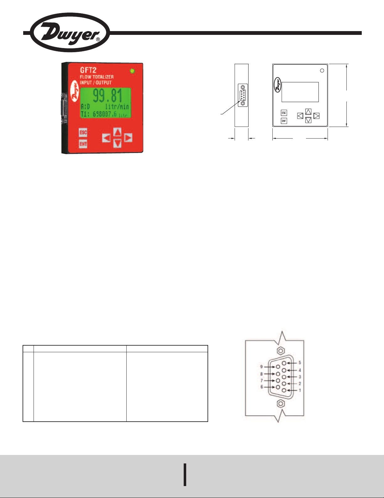
9-PIN FEMALE
I/O PORT
4
7/64
[
18.8]
3
[
76.2]
3-13/32
[86.36]
GFT2
F
LOW TOTALIZER
INPUT/OUTPUT
STATUS
Series GFT2 Flow Totalizer
Specifications - Installation and Operating Instructions
he Series GFT2 Flow Totalizer is a microcontroller driven device designed to
T
linearize the flow meter and controller flow curve plus display the instantaneous
flow rate, total, and accumulated total. The totalizer is intended to be used with
analog flow meters and controllers with analog 0 to 5 VDC, 0 to 10 VDC, or 4 to
20 mA interface. RS-232 or RS-485 digital interface is available.
EATURES
F
Up to 47 different volumetric and mass flow engineering units (including user-
•
defined)
• User adjustable LCD back light and contrast level
• Compact design for unit mount, panel mount, wall mount, or field mount
applications
• Low and high flow alarms with programmable action delay.
• Free configuration and mounting utility software
• 0.51˝ (13 mm) LCD digits
Unpacking the Totalizer
The Totalizer was packed in a sturdy cardboard carton. Inspect the package for
possible external damage from shipping. Open the carton carefully and inspect for
any sign of concealed shipping damage. When unpacking make sure that all
hardware is included. The hardware should include:
(1) GFT2
(1) CD with Utility Software and operating manual
(1) Mounting Bracket with 4 screws
Safety Instructions
The GFT2 is not intended for use in life support applications or where
malfunctioning of a device may cause personal injury. When adjusting or servicing
the GFT2, take special precaution to prevent inadvertent damage to the integral
solid state circuitry.
Electrical Connection
Function
Pin
Power Supply, Common
1
Power Supply, Positive
2
RS-232 RX, Optional RS-485 (+)
3
Analog Input (+), PV Input
v4
Analog Output (+), PV set point
5
RS-232 Signal GND (RS-485 GND Optional)
6
RS-232 TX, Optional RS-485 (-)
7
Analog Input/Output reference
8
common for pins 4 and 5)
9
5VDC reference input (for 5 to 10 VDC only)
Table 1
Note
Power Input
Power Input 12 to 26 VDC
Communication
(RS-232 is input, RS_485 input/output)
Input
Output
Communication Reference
Communication
(RS-232 is output, RS-485 input/output)
SPECIFICATIONS
nput Analog Range: 0 to 5 VDC, 0 to 10 VDC, or 4 to 20 mA.
I
ccuracy: ±0.1% FS.
A
perating Temperature: 14 to 158°F (-10 to 70°C).
O
Power Supply: 12 to 26 VDC.
Weight: 0.3 lbs (125 g)..
“D” Connector
DWYER INSTRUMENTS, INC.
Phone: 219/879-8000 www.dwyer-inst.com
P.O. BOX 373 • MICHIGAN CITY, INDIANA 46360, U.S.A. Fax: 219/872-9057 e-mail: info@dwyer-inst.com
Page 2
he power supply (PS), process variable (PV) input, set point (SP) control output, and
G
F
T2
#
1
G
F
T2
#
2
G
F
T2
#
3
G
F
T2
#
4
G
F
T2
#
N
T
erial communication interface signals are connected to the GFT2 via miniature 9 pin
s
emale “D” connector.
f
Power Supply Connections
The power supply requirements for the GFT2 are: 12 to 26 VDC, (unipolar power
upply).
s
C Power (+) --------------- Pin 4 of the 9 pin “D” connector
D
C Power (-) --------------- Pin 8 of the 9 pin “D” connector
D
AUTION
C
-Do not apply power voltage above 28 VDC. Doing so will
cause device damage or faulty operation.
-Make sure power is OFF when connecting or disconnecting any cables or wires in
he system.
t
ower Variable (PV) Input Signal Connections
P
epending on jumper J2 configuration, input signal can be set to 0 to 5, 0 to 10VDC,
D
or 4 to 20 mA.
S-232 Serial Communication Interface Connections
R
he digital interface operates via RS-232 and provides access to all applicable
T
nternal configuration parameters and data.
i
The settings for the RS-232 communication interface are:
Baud rate: default 9600 baud
Stop bit: 1
ata bits: 8
D
arity: None
P
low control: None
F
The RS-232 Communication Interface Connection must establish a crossover
connection form the PC host connector to the “D” connector.
RS-232 RX: Pin 2 on the host PC DB9 connector - Pin 7 of the 9 pin “D” connector
TX-)
(
S-232 TX: Pin 3 on the host PC DB9 connector - Pin 3 of the 9 pin “D” connector
R
RX-)
(
S-232 Signal GND: Pin 5 on the host PC DB9 connector - Pin 6 of the 9 pin “D”
R
connector
CAUTION
ated values shown in the specifications in Table 2. Failure to do so might cause
r
amage to this device. Be sure to check if the wiring and the polarity of the power
d
hen connecting the external signals to the input terminals,
W
lways check actual jumper J2 configuration. Do not exceed the
a
supply and PV signals are correct before turning the power ON. Wiring error may
cause damage or faulty operation.
Maximum Rated Values for PV Input Signals
PV Input
Type
0 to 5 VDC
0 to 10 VDC
4 to 20 mA
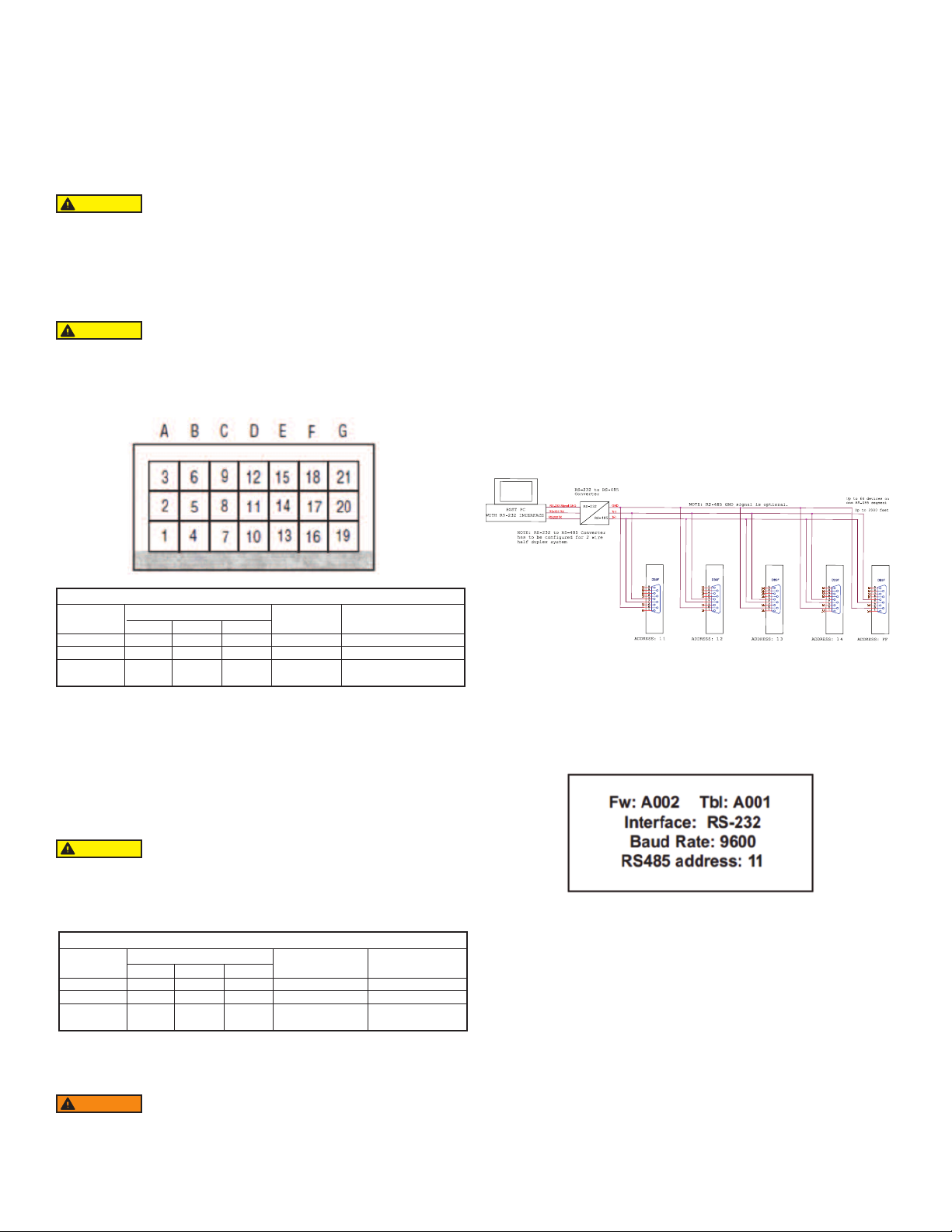
J2 Jumper Configuration
J2D
10 to 11
11 to 12
10 to 11
J2E
14 to 15
14 to 15
13 to 14
17 to 18
17 to 18
16 to 17
J2F
Maximum
Signal Level
≤6 VDC
≤11 VDC
≤25 mA
Note
249 Ω Passive, Not
Isolated Current Input
Table 2
DC Power (+) --------------- Pin 4 of the 9 pin “D” connector
DC Power (-) --------------- Pin 8 of the 9 pin “D” connector
Set Point (SP) Output Signal Connections
Set Point (SP) output signal connection is only required if the GFT2 is mated to the
flow controller and will be used as a source for Set Point control signal. Depending on
the jumper J2 configuration, the SP output signal can be set to 0 to 5, 0 to 10 VDC or
4 to 20 mA.
RS-485 Communication Interface Connection:
he RS-485 converter/adaptor must be configured for: multidrop, 2-wire, half duplex
T
ode (see Figure 6). The transmitter circuit must be enabled by TD or RTS
m
depending on which is available on the converter/adapter). Settings for the receiver
(
circuit should follow the selection made for the transmitter circuit in order to eliminate
echo.
RS-485 T(-) or R(+) pin 7 of the 9 pin “D” connector (TX-)
S-485 T(+) or R(-) pin 3 of the 9 pin “D” connector (RX+)
R
S-485 GND (if available) pin 6 of the 9 pin “D” connector
R
Figure 1 RS-485 Multidrop Half Duplex Two Wire System
LCD Key-Pad Operation: Data Entry and Configuration
Display Indications:
Initially, after the power is first turned on, the banner screen is shown for 2 seconds,
then the device firmware and EEPROM data base table revisions on the first line,
communication interface type on the second line, baud rate and RS-485 hexadecimal
address value on the third and fourth lines are shown for another 2 seconds.
Subsequently, the actual process information (PI) is displayed.
CAUTION
When connecting the load to the output terminals always check
actual jumper J2 configuration. Do not exceed the rated values
shown in Table 3. Failure to do so might cause damage to this device. Be sure to
check if the wiring and the polarity of the power supply and SP signals are correct
before turning the power ON. Wiring error may cause damage or faulty operation.
Do not connect external voltage source to the SP output terminals.
Maximum Rated Load Impedence for SP Output Signals
SP Output
Type
0 to 5 VDC
0 to 10 VDC
4 to 20 mA
J2 Jumper Configuration
J2A
2 to 3
2 to 3
1 to 2
J2B
5 to 6
5 to 6
4 to 5
J2C
8 to 9
8 to 9
7 to 8
Maximum
Load Impedence
≤1000 Ω
≤5000 Ω
≤900 Ω
Note
Self powered
(non-isolated)
Table 3
DC Power (+) --------------- Pin 5 of the 9 pin “D” connector
DC Power (-) --------------- Pin 8 of the 9 pin “D” connector
WARNING
The 4 to 20 mA current loop output is self-powered (non-
isolated). Do NOT connect an external voltage source to the
output signals.
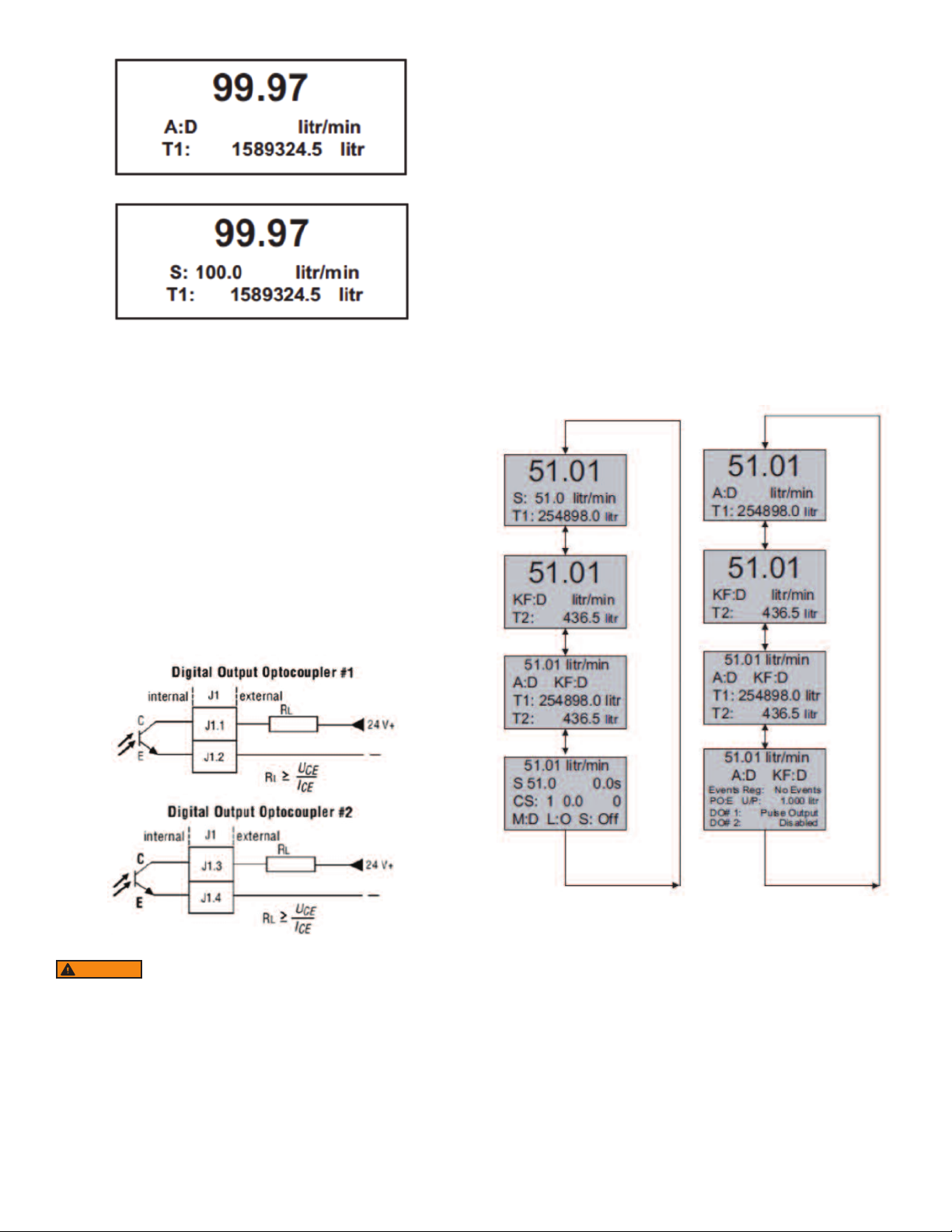
Figure 2
Based on configuration (device function as flow meter or flow controller), different
parameters may be displayed in the Process Information (PI) screen by pressing the
UP or DN pushbuttons.
Process Information screens can be configured to be static or dynamic. Using the
Screen mask settings, the user can enable (unmask) or disable (mask) up to 4
different process information combinations (see Figure 6). In static mode the UP
button pages through the PI screens in the forward direction, the DN button pages
through the PI screens in the reverse direction. When the last PI screen is reached,
the firmware “wraps around” and scrolls to the initial PI once again.
In the Dynamic display mode, firmware initiates automatic screen sequencing with
user-adjustable screen Cycle Time. When the last PI screen is reached, the firmware
“wraps around” and scrolls to the initial PI screen once again.
NOTE: Actual content of the LCD screen may vary depending on the model and
device configuration.
Page 3
igure 3 - Initial PI Screen (Flow Meter)
F
djusting the Set Point using local LCD/Keypad: Current Set Point value is
A
isplayed on the second line of the main PI screen, next to the ‘S’ character. See
d
igure 7.
F
Pressing the ENT button while in the PI screen will activate Set Point adjustment
mode. The first character of the Set Point value will start to flash. Use the UP or DN
button to increase/decrease digit value from 0 to 9. Use RIGHT or LEFT buttons to
ove the cursor to another digit position. When desired Set Point value is entered,
m
se the ENT button to accept the new Set Point value. If in the end of the Set Point
u
alue entry the ESC button is pressed instead of ENT, the original Set Point value
v
ill be restored and Set Point adjustment mode will be deactivated. To exit form the
w
Set Point adjustment mode before Set Point value is accepted, press ESC button.
NOTE: Since the Set Point value entered via local LCD/keypad is stored in the non
olatile memory (EEPROM), it will be executed on the next device power up event.
v
OTE: If Program Set Point mode is enabled and the program is running, the Set
N
Point value can be changed at any moment by the execution of the next active step.
Figure 4 - Initial PI Screen (Flow Controller)
When GFT2 device is set as the last device on the RS-485 bus segment, and 220
Ohm bus termination is required, set jumper J2G to position 19-20. This will result
in connection 220 Ohm resistor between RS-485 (+) and (-) terminals.
igital and Pulse Optically-Isolated Outputs and Connections
D
FT2 is equipped with two programmable digital optically-isolated outputs. Each
G
utput can be assigned to any one of many different system events or configured
o
as pulse output.
Digital optically-isolated outputs use dedicated 4 position 3.5 mm male terminal
block header J1 located on the top side of the GFT2 enclosure . (Mated interface
onnector: Tyco Electronics P/N 284510-4)
c
ptocoupler #1 - Terminal J1 (pins 1 and 2):
O
Plus (+) (passive) Terminal J1 pin 1
Minus (-) (passive) Terminal J1 pin 2
Optocoupler #2 – Terminal J1 (pins 3 and 4):
Plus (+) (passive) Terminal J1 pin 3
Minus (-) (passive) Terminal J1 pin 4
Controlling Set Point value using Program Set Point Mode:
In order to activate the Programmed Set Point:
. Program Set Point mode has to be enabled.
1
. Program Loop parameter has to be set to desired value (On/Off).
2
. Program Run parameter has to be set to “On”.
3
Figure 5
WARNING
limits for voltage and current: 2V < UCE < 40 V, 0.2 mA < ICE < 150 mA.
Set Point Control (only for devices set as controller)
When the GFT2 is configured as controller it can be used to control the set point
value for mated flow controller using the analog output interface. The set point
value can be adjusted locally using the LCD/ keypad, remotely via RS-232/RS-485
digital interface, or can be programmed in advance using user preset programs of
up to sixteen steps (Program Set Point Mode).
NOTE: Before applying power and process signals, make sure the input/output
jumpers are installed in the correct position (see Figure 6).
Optically-isolated outputs require application of external DC
voltage across terminals. Do not exceed maximum allowed
Figure 6
Page 4
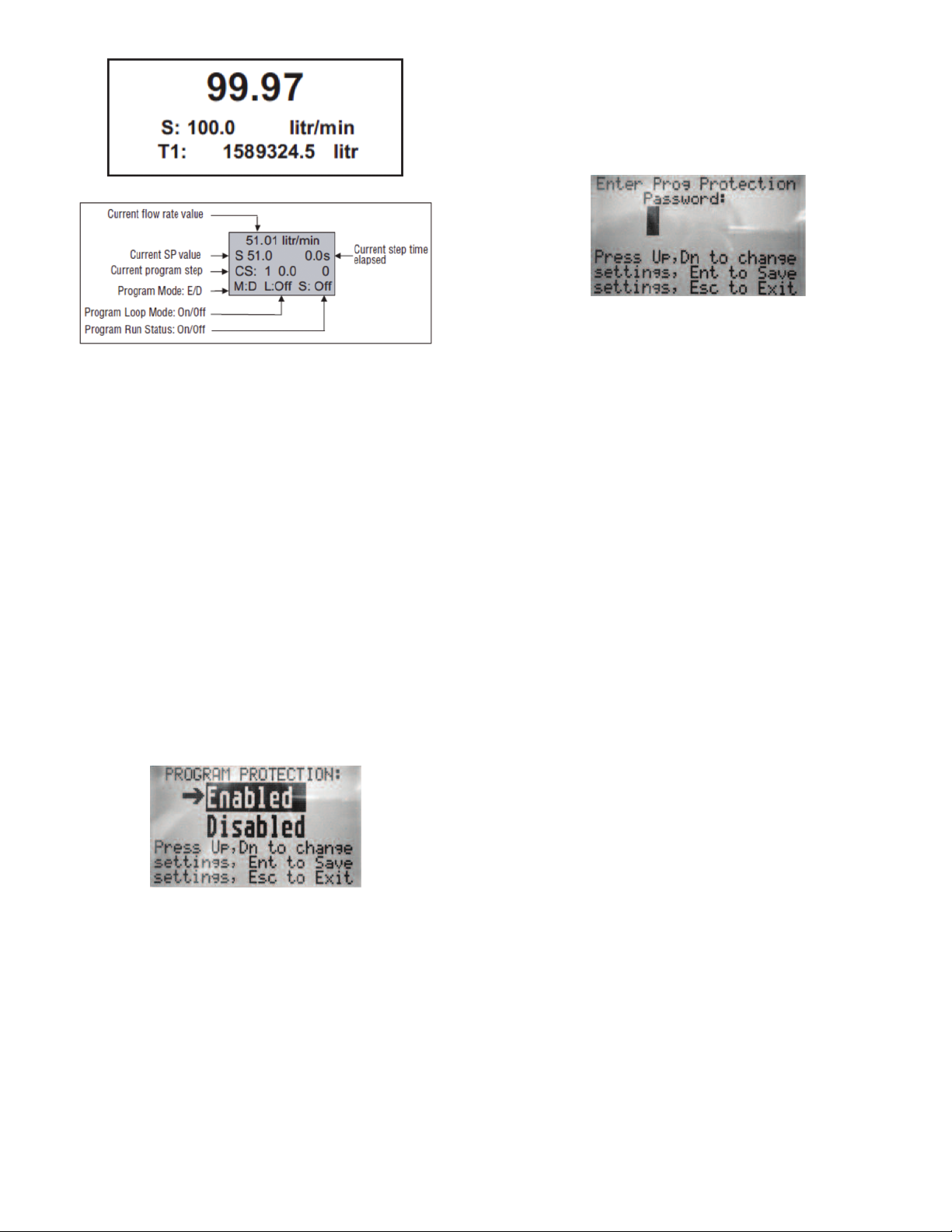
igure 7
F
As shown in the above picture, the program run parameter can be toggled “On” and
“Off” by pressing RIGHT and LEFT keypad buttons while PI screen 4 is active. If
he Program Run status parameter set to “Off”, the program execution will pause
t
nd current SP value will freeze until the Program Run status parameter is set to
a
On”.
“
NOTE: While Program Set Point mode is running, the current Set Point value also
can be changed from local LCD/keypad and digital RS-232 communication
interface. In this case, new Set Point value will be kept only until the next
uccessive program step will be executed.
s
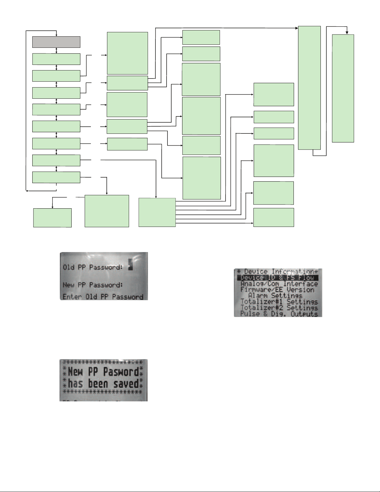
enu Structure
M
The diagram on the Figure 10 gives a general overview of the standard top-level
display menu structure when running firmware version A001. The ESC pushbutton
is used to toggle between the Process Mode (PI screens) and the Setup menus.
UP and DN buttons must be used to move through the menu items. When the last
item in the menu is reached, the menu “wraps around” and scrolls back to the
beginning of the menu items list. Similarly when the first menu item is highlighted
and UP button is pressed, the menu “wraps around” and scrolls down to the end of
the menu items list.
All process configuration parameters settings are password protected. In order to
access or change them, Program Protection should be disabled. Each time the
device is powered up, the Program Protection is enabled automatically. By default
,device is shipped from the factory with Program Protection (PP) password set to
Zero (PP Disabled). If PP password is set to Zero (Disabled), entering PP password
is not required and a following screen will appear when Program Protection menu
item will be selected. (See Figure 8).
ressing the UP or DN button to select the Disabled option and then the ENT
P
utton to save settings will disable program protection.
b
f PP password is set to any value more than Zero, the firmware will prompt with
I
“Enter PP Password” (see Figure 9). User must enter up to 3 digits program
protection code in order to be able to access password protected menus. Once the
correct password is entered, Program Protection is turned off until the unit is
owered up again.
p
Figure 9
Parameter Entry
There are two methods of data entry:
. Direct numerical number entry.
1
. Tabular Input from a table menu.
2
If the menu with direct numerical entry is selected, use the UP or DN button to
increase/decrease digit value from 0 to 9. Use the RIGHT or LEFT button to move
the cursor to another digit position. When the desired value is entered, use ENT
button to accept (save in the EEPROM) the new value.
OTE: During data entry, the input values are checked for acceptability. If data is
N
ot acceptable, it is rejected and a message indicates that the new data has not
n
been accepted.
If the menu with tabular entry is selected, the available menu options can be set
with the UP or DN buttons and are accepted by pressing the ENT button.
Submenu “Change PP Password”
In order to get access to “Change PP Password” menu, program protection must
be disabled. If PP password is set to Zero (Disabled), entering PP Password is not
required and PP can be disabled from “Program Protection” menu (see Figure 3).
If PP Password is set to any value more than Zero, the firmware will prompt with
“Enter PP Password” (see Figure 9). User must enter program protection code
(up to 3 digits). If PP password is lost or forgotten, contact Dwyer Instruments.
Figure 8
Page 5
Once “Change PP Password” menu is selected, the following screen will appear:
P
ro
g
ram
P
ro
t
a
c
t
i
o
n
(P
P
)
C
h
an
g
e
P
P
Pa
s
s
wo
r
d
D
e
v
ic
e
In
fo
r
ma
ti
o
n
E
n
g
U
n
i
ts
&
K
-
F
a
c
to
r
T
o
ta
l
iz
e
r
S
et
ti
n
g
s
O
p
t
Ou
tp
u
t
S
et
ti
n
g
s
G
e
n
e
r
a
l
S
e
tt
i
ng
s
D
evice
D
iagn
o
stic
A
la
r
m
Se
t
ti
n
g
s
*
*
*
*
*
M
a
i
n
M
e
n
u
*
*
*
*
*
U
p
/
D
n
E
ven
t R
egis
ter M
en
u
A
na
log In
p
ut count
s
A
nal
og Outp
ut V
alu
e
LCD
B
ack
Ligh
t S
e
t.
P
uls
e O
utpu
t Qu
eue
CP
U
T
e
m
peratur
e
D
evice
D
iagn
o
stic
O
p
t
O
u
t
p
u
t
#
1
S
e
t
O
p
t
O
u
t
p
u
t
#
2
S
e
t
T
o
ta
li
ze
r
#
1
To
ta
l
i
ze
r
#
2
P
u
l
se
O
u
tp
u
t
Fl
o
w
A
l
a
r
m
M
o
d
e
L
o
w
Fl
o
w
A
la
r
m
H
i
g
h
Fl
o
w
A
l
a
r
m
Fl
o
w
A
l
a
r
m
D
e
l
a
y
Fl
o
w
A
l
a
r
m
L
a
t
ch
M
e
a
su
r
i
n
g
U
n
its
U
se
rD
e
f
i
n
e
d
U
n
its
K
-
Fa
cto
r
S
e
t
tin
g
s
D
e
vi
ce
ID
&
FS
Fl
o
w
A
n
a
l
o
g
/C
o
m
In
te
rfa
c
e
Fi
rm
w
a
re
/E
E
V
e
r
sio
n
A
l
a
rm
S
e
t
tin
g
s
T
o
ta
li
ze
r
#
1
S
e
t
tin
g
s
T
o
ta
li
z
e
r
#
2
S
e
t
tin
g
s
P
u
l
se
&
Di
g
.
O
u
t
p
u
ts
M
a
te
d
D
e
vic
e
In
f
o
G
e
n
e
r
a
l S
e
tt
in
g
s
D
i
sp
la
y
M
o
d
e
S
cre
e
n
C
ycl
e
T
i
m
e
S
cr
e
e
n
M
a
sk
D
i
sp
la
y
B
a
ck
L
i
g
h
t
D
i
s
p
la
y
C
o
n
tra
s
t
Fl
o
w
M
e
te
r
Fl
o
w
Co
n
t
r
o
ll
e
r
B
a
u
d
Ra
te
S
e
t
tin
g
s
R
S
-
4
8
5
B
u
s A
d
d
r
e
s
s
Fu
ll S
ca
l
e
R
a
n
g
e
L
o
w
Flo
w
C
u
t-o
ff
Fl
o
w
P
o
w
e
r
U
p
D
e
l
a
y
Fl
u
id
S
td
.
D
e
n
sit
y
A
n
a
lo
g
O
u
tp
u
t
C
a
l
.
A
n
a
lo
g
I
n
p
u
t
Ca
l.
P
i
lot C
a
l.
T
im
e
r
S
ignal
Con
dit
. M
ode
NR
F Nu
m
. of Sam
ples
NR
F T
im
e In
terva
l
A
ver.Fi
lter Dam
ping
Flow
Lin
earize
r M
ode
P
rogram
S
P
M
ode
P
S
P
Lo
o
p M
ode
P
S
P
S
t
eps M
a
sk
P
S
P
S
t
eps S
et
tings
T
o
t
a
l
ize
r #
1
M
o
d
e
T
o
t
#
1
Fl
o
w
S
ta
r
t
T
o
t
#
1
A
ctio
n
V
o
l
.
T
o
t
#
1
P
o
w
e
r
O
n
De
l
a
y
T
o
t
#
1
A
u
t
o
R
e
se
t
T
o
t
#
1
A
u
to
Re
s D
e
l
a
y
R
e
se
t
T
o
t
a
liz
e
r #
1
T
o
t
a
l
ize
r #
2
M
o
d
e
T
o
t#
2
C
o
n
fi
g
u
r
a
tio
n
T
o
t
#
2
Fl
o
w S
ta
r
t
T
o
t
#
2
A
ctio
n
V
o
l
.
T
o
t
#
2
P
o
w
e
r
O
n
D
e
l
a
y
T
o
t
#
2
A
u
to
R
e
lo
a
d
T
o
t
#
2
A
u
to
Re
l
D
e
la
y
R
e
se
t
T
o
t
a
liz
e
r #
2
P
u
l
s
e
O
u
t
p
u
t
M
o
d
e
P
u
l
se
F
lo
w
S
t
a
r
t
[U
n
i
t
]/
P
u
lse
P
u
l
se
A
c
t
i
v
e
T
i
m
e
D
i
sa
b
le
d
L
o
w
F. A
la
r
m
H
i
g
h
F.
A
l
a
rm
F. R
a
nge H
-
L
Total#
1
E
vent
T
otal#2
E
vent
P
ulse O
utput
D
iagnos
tic
M
anua
l
On
U
D
U
n
i
t
K
-
F
a
cto
r
U
D
U
n
i
t
T
im
e
B
a
se
U
D
U
n
i
t
Use
D
e
n
si
t
y
K
-F
a
c
t
o
r M
o
d
e
I
n
t
.
K
-
Fa
c
to
r
In
d
e
x
U
se
r
D
e
f
'
d
K
-
Fa
cto
r
%
F
S
m
l
/s
e
c
m
l
/
m
i
n
m
l
/
h
r
m
l
/
d
a
y
l
i
t
r
/
s
e
c
l
i
t
r
/
m
i
n
l
i
t
r
/
h
r
l
i
tr
/
d
a
y
m
^
3
/
s
e
c
m
^
3
/
m
i
n
m
^
3
/
h
r
m
^
3
/
d
a
y
f
^
3
/
s
e
c
f
^
3
/
m
i
n
f
^
3
/h
r
f
^
3
/
d
a
y
g
a
l
/s
e
c
g
a
l
/m
i
n
g
a
l
/
h
r
g
a
l
/
d
a
y
g
r
a
m
/
s
e
c
g
r
a
m
/
m
i
n
g
r
a
m
/
h
r
g
r
a
m
/
d
a
y
k
g
/
s
e
c
k
g
/
m
i
n
k
g
/
h
r
k
g
/d
a
y
l
b
/
s
e
c
l
b
/
m
i
n
l
b
/
h
r
l
b
/
d
a
y
M
t
o
n
/
m
i
n
M
t
o
n
/
h
r
I
g
a
l
/s
e
c
I
g
a
l
/m
i
n
I
g
a
l
/
h
r
I
g
a
l
/
d
a
y
M
i
l
L
/
m
i
n
M
i
l
L
/h
r
M
i
l
L
/d
a
y
b
b
l
/s
e
c
b
b
l
/m
i
n
b
b
l
/h
r
b
b
l
/
d
a
y
U
s
e
r
E
n
t
E
ven
t R
eg. S
tatus
E
ven
t Latch
M
ask
E
ven
t R
eg. M
ask
R
e
s
et E
ven
t R
eg.
D
isplay S
etting
s
D
e
vice F
unction
C
om
m
u
nica
tio
n S
e
tt.
D
e
vice C
alibrati
on
S
ignal C
on
dition
er
P
rogram
S
et P
oin
t
E
nt
E
n
t
E
n
t
E
n
t
E
n
t
E
n
t
E
n
t
Figure 11
Figure 12
In order to protect device configuration parameters when changing the PP
password, the old PP password must be entered.
NOTE: By default, the device shipped from the factory with Program Protection
(PP) password set to Zero (PP Disabled).
Once old and new passwords are entered, the firmware will prompt with a
confirmation message (see Figure 12) that the new password has been saved.
Figure 10
Submenu “Device Information”
This submenu contains information about the device’s main configuration
parameters. These items are informational only, not password-protected, and can
not be changed (read only).
Submenu “Measuring Units”
Use the “Engineering Units and K-Factor Menu” to navigate to “Measuring Units”
menu option. This option allows configuration of the flow meter/controller with the
desired units of measurement. These are global settings and determine what
appears on all process information screens and data log records. Units should be
selected to meet each particular metering need. A total of 47 different volumetric
and mass based engineering units are supported (See Table 4).
NOTE: Program the Measuring Units first because subsequent menus may be
based on the units selected. Once Flow Unit of Measure is changed, the Totalizer’s
Volume based Unit of Measure will be changed automatically.
Fi
gur
e
1
3
Page 6

ubmenu “User-Defined Units”
S
n addition to conventional flow units, user-defined flow engineering units may be
I
elected. Use the “Engineering Units and K-Factor Menu” to navigate to the “User
s
efined Units” menu option. This option enables user-defined configuration of any
D
engineering unit required for process measurement.
The following three parameters are available for this function:
. UD Unit volume K-Factor (defined in Liters)
1
. UD Unit time base (defined in Seconds)
2
. UD Unit use density (units with or without density support)
3
Before using User-Defined Unit, make sure the proper conversion factor of the new
unit with respect to one liter is set (the default entry is 1.00 Liter). Also, proper time
base values for User-Defined Units must be set.
he following selections are available: 1 second, 60 seconds (1 minute), 3600
T
econds (1 hour), 86400 seconds (1 day). The default entry is 60 seconds. If a
s
mass based User-Defined Unit is desired, then “UD Unit Use Density” parameter
must be set to “YES”. The default entry is “NO”, so Fluid STD Density parameter is
not used for flow rate calculation.
low Rate
umber
N
F
ngineering
E
nits
U
1
2
3
4
5
6
7
8
9
0
1
11
12
13
14
15
16
17
18
19
20
21
22
23
24
25
26
27
28
29
30
31
32
33
34
35
36
37
38
39
40
41
42
43
44
45
46
47
%FS
ml/sec
l/min
m
ml/hr
ml/day
itr/sec
l
litr/min
litr/hr
litr/day
^3/sec
m
m^3/min
m^3/hr
m^3/day
f^3/sec
f^3/min
f^3/hr
f^3/day
gal/sec
gal/min
gal/hr
gal/day
gram/sec
gram/min
gram/hr
gram/day
kg/sec
kg/min
kg/hr
kg/day
lb/sec
lb/min
lb/hr
lb/day
Mton/min
Mton/hr
lgal/sec
lgal/min
lgal/hr
lgal/day
MilL/min
MilL/hr
MilL/day
bbl/sec
bbl/min
bbl/hr
bbl/day
User
Table 4: Supported Engineering Units List
otalizer
T
ngineering
E
nits
U
%s
ml
l
m
ml
ml
itr
l
litr
litr
litr
^3
m
m^3
m^3
m^3
f^3
f^3
f^3
f^3
gal
gal
gal
gal
gram
gram
gram
gram
kg
kg
kg
kg
lb
lb
lb
lb
Mton
Mton
lgal
lgal
lgal
lgal
MilL
MilL
MilL
bbl
bbl
bbl
bbl
User
escription
D
Percent of full scale
Mililiter per second
ililiter per minute
M
Mililiter per hour
Mililiter per day
iter per second
L
Liter per minute
Liter per house
Liter per day
ubic meter per second
C
Cubic meter per minute
Cubic meter per hour
Cubic meter per day
Cubic feet per second
Cubic feet per minute
Cubic feet per hour
Cubic feet per day
Gal per second
Gal per minute
Gal per hour
Gal per day
Grams per second
Grams per minute
Grams per hour
Grams per day
Kilograms per second
Kilograms per minute
Kilograms per hour
Kilograms per day
Pounds per second
Pounds per minute
Pounds per hour
Pounds per day
Metric Ton per minute
Metric Ton per hour
Imperial Gal per second
Imperial Gal per min
Imperial Gal per hour
Imperial Gal per day
Million Litr per minute
Million Litr per hour
Million Litr per day
Barrel per second
Barrel per minute
Barrel per hour
Barrel per day
User Defined
ubmenu “K-Factors Settings”
S
onversion factors relative to Nitrogen are convenient to use when flow
C
eter/controller mated to GFT2 is calibrated for Nitrogen and another gas is
m
equired to be measured/controlled.
r
Conversion factors relative to Nitrogen, for up to 22 common gases, are stored in
the GFT2. In addition, provision is made for a user-defined conversion factor.
onversion factors may be applied to all units of measure (except %FS unit) via
C
CD/Keypad or serial communication interface.
L
he following three parameters are available for this function:
T
K-Factor Mode: Disable, Internal Index, User-Defined (default Disabled)
Internal K Factor Index: 1 – 22 (from internal K-Factor table)
User-Defined K-Factor: 0.001 – 999.9 (default value is 1.000)
OTE: The conversion factors will not be applied for % FS engineering unit.
N
Submenu “Alarm Settings”
GFT2 provides the user with a flexible alarm/warning system that monitors the Fluid
Flow for conditions that fall outside configurable limits, as well as visual feedback
for the user via the LCD or via an optically-isolated output. The Flow Alarm has
everal attributes which may be configured by the user via LCD/Keypad or serial
s
ommunication interface. These attributes control the conditions which cause the
c
larm to occur and to specify actions to be taken when the flow rate is outside the
a
specified conditions.
Depending on the GFT2 function configuration (flow meter or controller) there are
two Alarm algorithms. If GFT2 is configured as flow meter, flow Alarm conditions
ecome true when the current flow reading is equal to or higher/lower than
b
orresponding values of high and low flow Alarm levels. If GFT2 is configured as
c
low controller, flow Alarm conditions become true when difference between Set
f
Point value and current flow reading is equal or higher/lower than corresponding
values of High and Low Flow Alarm levels.
Alarm actions can be assigned with preset Delay Interval (0-3600 seconds) to
activate the optically-isolated output (separate for High and Low alarm). Latch
Mode control feature allows each optical output to be latched on or follow the
corresponding alarm status.
The following settings are available for Flow Alarm (see Figure 10):
a) Flow Alarm Mode (Tabular entry)
This function determines whether Flow Alarm is Enabled or Disabled. The following
sections are available: Enabled or Disabled. The default entry is Disabled. Alarm
Mode selections can be set with the UP and DN buttons and are accepted by
pressing ENT button.
b) Low Flow Alarm (Numerical entry)
The limit of required Low Flow Alarm value can be entered in increments of 0.1%
from 0 – 100% FS.
If a Low Alarm occurs and one of the two optional outputs is assigned to the Low
Flow Alarm Event, the optically-isolated output will be activated:
1) For Flow Meter Function: when the flow is less than the Low Flow Alarm value.
2) For flow controller function: when the absolute difference between Set Point
value and actual flow reading is equal or more than the Low Flow Alarm value and
Actual Flow value is less than Set Point value.
The Low Flow Alarm condition is also indicated on the corresponding Process
Information Screen displaying L character.
NOTE: For Flow Meter function, the value of the Low Flow Alarm must be less than
the value of the High Flow Alarm
c) High Flow Alarm (Numerical entry)
The limit of required High Flow Alarm value can be entered in increments of 0.1%
from 0 – 100% FS. If a High Alarm occurs and one of the two optical outputs is
assigned to the High Flow Alarm Event, the optically-isolated output will be
activated for:
a) Flow Meter function: when the flow is more than the High Flow Alarm value.
b) Flow Controller function: when absolute difference between Set Point value and
Actual Flow reading is equal or more than the High Flow Alarm value and actual
flow value is more than Set Point value.
The High Flow Alarm condition is also indicated on the corresponding Process
Information Screen by displaying H character.
NOTE: For Flow Meter function, the value of the High Flow Alarm must be more
than the value of the Low Flow Alarm.
Page 7
) Flow Alarm Action Delay (Numerical entry)
d
he Flow Alarm Action Delay is a time in seconds that the Flow Rate value remain
T
above the high limit or below the low limit before an alarm condition is validated.
s
alid settings are in the range of 0 to 3600 seconds (default value is 0, no delay).
V
e) Flow Alarm Action Latch (Tabular entry)
The Flow Alarm Action Latch settings controls the Latch feature. If optically-isolated
utput is assigned to the Flow Alarm Event, in some cases, the Flow Alarm Latch
o
eature may be desirable.
f
he following settings are available: Disable or Enable. By default, Flow Alarm is
T
non-latching. That means the alarm is indicated only while the monitored Flow
Value exceeds the specified set conditions.
ubmenu “Totalizer #1”
S
FT2 provides the user with two independent Programmable Flow Totalizers. The
G
otal volume of the flowing fluid is calculated by integrating the actual instantaneous
t
fluid flow rate with respect to time. Totalizer #1 (main totalizer) value is stored in the
EEPROM and saved every (1) second. In case of power interruption, the last saved
Totalizer value will be loaded on the next power on cycle, so main totalizer reading
will not be lost. Use the “Totalizer Menu” to navigate to the “Totalizer #1” menu
ption. The following settings are available for Totalizer #1 (see Figure 10).
o
) Totalizer #1 Mode (Tabular entry)
a
This option determines whether Totalizer #1 is Enabled or Disabled. The following
selections are available: Enabled or Disabled. The default entry is Disabled.
Totalizer #1 Mode selections can be set with the UP and DN buttons and are
accepted by pressing ENT button.
OTE: Before enabling the Totalizer, ensure that all totalizer settings are
N
onfigured properly. Totalizer Start values have to be entered in the currently active
c
Volumetric or Mass flow engineering unit. The Totalizer will not totalize until the
Process Flow Rate becomes equal to or more than the Totalizer Start value.
Totalizer Event values must be entered in currently active volume or mass based
engineering units. If the Totalizer Event at preset total volume feature is not
required, set Totalizer Event value to zero (default settings).
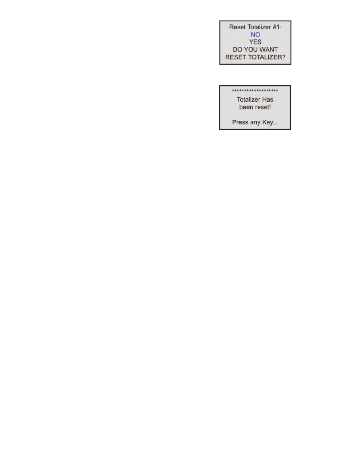
igure 14
F
nce the “YES” option is selected, Totalizer #1 will be reset and the following
O
onfirmation screen will appear:
c
Figure 15
Submenu “Totalizer #2”
he Totalizer #2 (pilot totalizer) value is stored in the flow meter volatile memory
T
SRAM) and saved every 100 milliseconds (0.1 second). In case of power
(
nterruption, the Totalizer #2 volume will be lost (reset to zero). It is preferable to
i
use Totalizer #2 for short term process flow calculation (for example: batch
processing). Use the “Totalizer Menu” to navigate to “Totalizer #2” menu option. The
following settings are available for Totalizer #2 (see Figure 10):
) Totalizer #2 Mode (Tabular entry)
a
his option determines whether Totalizer #2 is Enabled or Disabled. The following
T
elections are available: Enabled or Disabled. The default entry is Disabled.
s
Totalizer #2 Mode selections can be set with the UP and DN buttons and are
accepted by pressing ENT button.
b) Totalizer #1 Flow Start (Numerical entry)
This option allows the totalizer to start at a present flow rate. The Totalizer #1 will
not totalize until the process flow rate becomes equal to or more than the Totalizer
#1 Flow Start value. The limit of required Totalizer #1 Flow Start value can be
entered in increments of 0.1% from 0 to 100% FS.
c) Totalizer #1 Action Volume (Numerical entry)
This option allows the user to activate preset required action when the totalizer
reaches a preset volume. Totalizer #1 Action Volume value must be entered in
currently active volume/mass based engineering units. Totalizer #1 action event
becomes true when Totalizer #1 reading is more or equal to preset "Totalizer #1
Action Volume”. If the Totalizer #1 Action at preset total volume feature is not
required, set “Totalizer #1 Action Volume” value to zero (default settings).
d) Totalizer #1 Power On Delay (Numerical entry)
Sometimes it is convenient to start the Totalizer only after specified power up delay
interval. Most of the mass flow meters and controllers require some warm up time
from the power up event in order to stabilize process variable output and get
accurate reading. “Totalizer #1 Power On Delay” option allows set specified time
interval which must elapse from the device power up event before Totalizer will be
activated. Valid settings are in the range of 0 to 3600 seconds (default value is 0,
no delay).
e) Totalizer #1 Auto Reset (Tabular entry)
This option allows to automatically reset Totalizer #1 when it reaches preset Action
Volume value. This feature may be convenient for batch processing, when
predefined volume of the fluid must be repeatedly dispensed into the process. The
following selections are available: Enabled or Disabled.
The default entry is Disabled. Totalizer #1 Auto Reset selections can be set with the
UP or DN buttons and are accepted by pressing ENT button.
f) Totalizer #1 Auto Reset Delay (Numerical entry)
This option may be desirable when “Totalizer #1 Auto Reset” feature is enabled.
Valid settings are in the range of 0 to 3600 seconds (default value is 0, no delay).
g) Reset Totalizer #1 (Numerical entry)
The Totalizers #1 reading can be reset by selecting “Reset Totalizer #1” menu
option. A typical display with Totalizer #1 Reset screen is shown in Figure 14.
NOTE: Before enabling the Totalizer, ensure that all Totalizer settings are
configured properly. Totalizer Start values must be entered in currently active
Volumetric or Mass flow engineering unit. The Totalizer will not totalize until the
process flow rate becomes equal to or more than the Totalizer Start value. Totalizer
Event values must be entered in currently active volume or mass based
engineering units. If the Totalizer Event at preset total volume feature is not
required, then set Totalizer Event value to zero (default settings).
b) Totalizer #2 Configuration (Tabular entry)
Totalizer #2 can be configured to count up or down. When configured to count
down, be sure “Totalizer #2 Action Volume” parameter is set to the desired value of
more than zero. In this case Totalizer #2 Action Event will be activated when the
totalizer counts down to zero. The following selections are available: Count UP or
Count DN. The default entry is Count UP. Totalizer #2 configuration selections can
be set with the UP and DN buttons and are accepted by pressing ENT button.
c) Totalizer #2 Flow Start (Numerical entry)
This option allows the start of the totalizer at a preset flow rate. The Totalizer #2 will
not totalize until the process flow rate becomes equal to or more than the Totalizer
#2 Flow Start value. The limit of required Totalizer #2 Flow Start value can be
entered in increments of 0.1% from 0 -100%FS.
d) Totalizer #2 Action Volume (Numerical entry)
This option allows the user to activate preset required action when totalizer reaches
a preset volume when totalizer configured to count up, or zero value when totalizer
configured to count down. Totalizer #2 Action Volume value must be entered in
currently active volume/mass based engineering units. When set to count up,
Totalizer #2 Action Event becomeS true when the totalizer #2 reading is more or
equal to preset “Totalizer #2 Action Volume”. If the Totalizer#2 Action at preset total
volume feature is not required, set “Totalizer #2 Action Volume” value to zero
(default settings).
NOTE: When Totalizer #2 is configured to count down, be sure “Totalizer #2 Action
Volume” value is set to any value more than zero.
e) Totalizer #2 Power On Delay (Numerical entry)
Sometimes it is convenient to start Totalizer only after specified power up delay
interval. Most of the mass flow meters and controllers require some warm up time
from the power up event in order to stabilize process variable output and get
accurate reading. “Totalizer #2 Power On Delay” option allows set a specified time
interval which must elapse from the device power-up event before Totalizer will be
activated. Valid settings are in the range of 0 to 3600 seconds (default value is 0,
no delay).
Page 8
) Totalizer #2 Auto Reload (Tabular entry)
f
his option allows to automatically reset/reload Totalizer #2 when it reaches preset
T
ction Volume value (when configured to count UP
A
o count Down
t
predefined volume of the fluid must be repeatedly dispensed into the process. The
following selections are available: Enabled or Disabled. The default entry is
Disabled. Totalizer #2 Auto Reload selections can be set with the UP and DN
uttons and are accepted by pressing the ENT button.
b
) Totalizer #2 Auto Reset Delay (Numerical entry)
g
his option may be desirable when “Totalizer #2 Auto Reload” feature is enabled.
T
Valid settings are in the range of 0 to 3600 seconds (default value is 0, no delay).
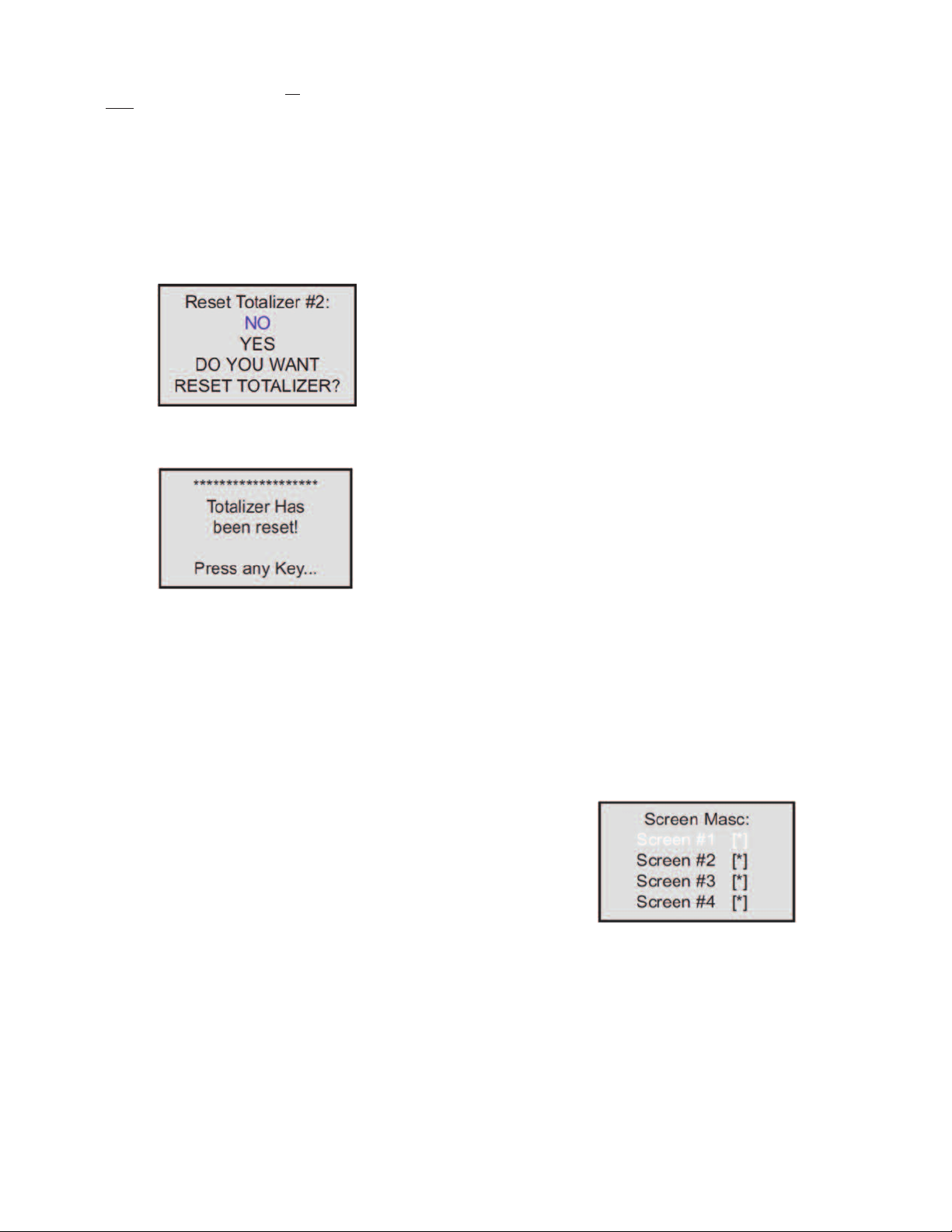
h) Reset Totalizer #2 (Numerical entry)
otalizers #2 reading can be reset by selecting “Reset Totalizer #2” menu option. A
T
ypical display with Totalizer #2 Reset screen is shown below.
t
Once “YES” option is selected, the Totalizer #2 will be reset and the following
onfirmation screen will appear.
c
. This feature may be convenient for batch processing when
)
igure 16
F
or zero value (when configured
)
he outputs can be made to switch when a specified event occurs (e.g. when a Low
t
r High Flow Alarm limit is exceeded or when the Totalizer reaches a specified
o
alue) or it may be directly controlled by user.
v
The user can configure each optical output action from 9 different options:
• Disabled: No Action (output is not assigned to any events and is not energized)
• Low Flow Alarm
High Flow Alarm
•
Range between High and Low Flow Alarm settings
•
Totalizer #1 reading exceed set limit
•
Totalizer #2 reading exceed set limit
•
• Pulse Output function
• Diagnostic: Output will be energized when any of the Diagnostic or System events
are active
Manual On Control: Output will be energized until Disabled option will be selected.
•
y default, both optically-isolated outputs are disabled.
B
NOTE: Optically-isolated outputs are accessible via screw terminal header J1 and
require application of external DC voltage across terminals. See Wiring Diagrams.
ubmenu “Display Settings”
S
rocess Information screens can be configured to be static (manual control) or
P
ynamic (automatic sequencing). In the static mode pressing the UP button allows
d
the user to page through the PI screens in the forward direction, pressing DN button
pages through the PI screens in the reverse direction. When the last PI screen is
reached, the firmware “wraps around” and scrolls to the initial PI screen once again.
OTE: PI screens which are masked in the Screen Mask Register (see below) will
N
e skipped.
b
Use the “General Settings” menu to navigate to “Display Settings” menu option
(see Figure 10).
Figure 17
Submenu “Pulse Output”
The flow Pulse Output is operating independently from totalizers and, based on
configuration settings (see Figure 10), can provide pulse frequency proportional to
instantaneous fluid flow rate.
The LCD/keypad and serial communication interface commands are provided to:
• Enable/Disable Pulse Output
• Start Pulse Output at preset flow rate (0.0 – 100.0%FS.
• Configure the Unit/Pulse value (in current engineering units)
• Configure Pulse Active On Time (10 – 6553 milliseconds)
NOTE: The Pulse Output minimum Active On time is 10 milliseconds (.01 second).
The Optical Pulse Output cannot operate faster than one pulse every 100
millisecond (.1 second). A good rule to follow is to set the Unit/Pulse value equal to
the maximum flow in the same units per second. This will limit the pulse rate to no
faster than one pulse every second.
For example: Maximum flow rate = 1200 kg/min
(1200 kg/min = 20 kg/sec)
If unit per pulse is set to 1200 kg/pulse, the Optical Pulse
Output will pulse once every minute.
If unit per pulse is set to 20 kg per pulse, the Optical Pulse Output will pulse once
every second.
The Optically-Isolated Pulse Output incorporate Pulse Output queue, which
accumulate pulses if the Pulse Output is accumulating process flow faster than the
Pulse Output hardware can function. The queue will allow the pulses to “catch up”
later if the flow rate decreases. A better practice is to slow down the Pulse Output
by increasing the value in the Unit/Pulse setting in the Pulse Output menu (see
Figure 10).
The following settings are available for LCD Display:
a) Display Mode (Tabular entry)
This option determines whether Display screens are in static (manual control) or
dynamic (automatic sequencing) mode. The following selections are available:
Static or Dynamic. The default entry is: Static (manual control). Display screens
mode parameter can be set with the UP and DN buttons and are accepted by
pressing ENT button.
b) Screen Cycle Time (Numerical entry)
This menu selection defines time interval in seconds for each PI screen to be
displayed in the dynamic mode (automatic sequencing). Screen Cycle Time can be
set to any value in the range between 1 to 3600 seconds (1 hour, numerical entry).
c) Screen Mask (Tabular entry)
Using Screen Mask settings the user can enable (unmask) or disable (mask) up to
4 different process variable combinations (see Figure 1). By default the unit is
shipped from the factory with all PI screens enabled. A typical display with Screen
Mask selection is shown below.
In the example shown above, all PI screens are enabled. Each PI screen assigned
Figure 18
to a corresponding bit in the PI Screen Register. In order to change PI Screen mask
settings, the user should select the desired screen using UP and DN buttons and
then press RIGHT button. The asterisk will appear/disappear on the right side of the
corresponding screen. The asterisk represents that the screen is enabled. In order
to disable the screen, the corresponding asterisk must be removed. Use the ENT
button to accept and save new PI Screen Mask settings in the device’s nonvolatile
memory.
NOTE: If Pulse Output feature is required, one of the Digital Optically- solated
outputs must be assigned to “Pulse Output” function. Pulse output signal will be
accessible via corresponding Digital Optically-Isolated output on the screw
terminal header J1 (see Wiring Diagrams).
Submenu “Opt. Outputs Settings”
Two sets of optically-isolated digital outputs are provided to actuate user-supplied
equipment. These are programmable via digital interface or LCD/Keypad such that
NOTE: PI Screen #1 cannot be disabled (unmasked).
d) Display Back Light (Numerical entry)
Using Display Back Light settings the user can adjust the desired level of the LCD
back light. The backlight has 19 different levels. Use UP and DN buttons to adjust
back light level and press ENT button to accept and save back light level settings
in the device’s nonvolatile memory.
Page 9

) Display Contrast (Numerical entry)
e
sing Display Contrast settings, the user can adjust the desired level of the LCD
U
ontrast. The contrast has 16 different levels. Use UP and DN buttons to adjust
c
ontrast level, and press ENT button to accept and save contrast level settings in
c
the device’s nonvolatile memory.
NOTE: By default, the contrast level is set to 6, which is the optimal level for room
emperature (20°C or 70°F).
t
ubmenu “Device Function”
S
his menu selection allows the selection of GFT2 function according to the mated
T
device type. If GFT2 is connected to the flow meter, then the “Meter” function must
be selected. If GFT2 is connected to the flow controller, then “Controller” function
must be selected.
OTE: Based on “Device Function” (device function as flow meter or flow
N
ontroller) settings, different parameters may be displayed in the Process
c
Information (PI) screen (see Figure 1) and different features of the GFT2 device
may be enabled or disabled (set point control only enabled when GFT2 is
configured as flow controller). Also, some features (e.g. Flow Alarm) may have
different behavior. Make sure the “Device Function” parameter is set according to
he actual device being used.
t
ubmenu “Communication Settings”
S
This menu selection allows the configuration of a serial communication interface
speed (Baud rate) and device RS-485 bus address (only applicable for optional RS485 interface). The following settings are available for “Communication Settings”
(see Figure 10).
) Baud Rate Settings (Tabular entry)
a
he Baud Rate Settings (Tabular entry) option determines device serial
T
communication interface speed (Baud rate) and can be set to one of the following:
1200, 2400, 4800, 9600, 19200, 38400, 57600, or 115200.
) Low Flow Cut-Off (Numerical entry)
b
he low flow cut-off can be selected between 0.0 and 10.0 % of the full-scale range.
T
lows less than the cut-off value are internally driven to zero and not totalized.
F
efault value of the “Low flow Cut-Off” parameter is zero (disabled).
D
c) Flow Power Up Delay (Numerical entry)
Sometimes it is convenient to start the process of the input signals after the
pecified power up delay interval. Most mass flow meters and controllers require
s
ome warm up time from the power up event in order to stabilize process variable
s
utput and get accurate reading. “Flow Power UP Delay” option allows set specified
o
ime interval, which has to elapse from the device power up event before
t
processing of the input signals will be activated. During active faze of the Power Up
Delay, the flow rate will be internally driven to zero and not totalized. Valid settings
are in the range of 0 to 3600 seconds (1 hour, default value is 0, no delay).
) Fluid Std. Density (Numerical entry)
d
he density of the flowing fluid at standard temperature and pressure conditions
T
should be in g/L. This parameter is used only when mass-based engineering units
are selected. Valid settings are in the range of 0.000001 to 10000.0 g/L. Factory set
default value is 1.25 g/L (Nitrogen).
) Analog Output Calibration
e
OTE: The analog outputs available on the GFT2 were calibrated at the factory.
N
There is no need to perform analog output calibration unless the DAC IC, output
amplifier IC, or passive components from analog output circuitries were replaced.
Any alteration of the analog output scaling variables in the EEPROM table will
VOID calibration warranty supplied with the instrument.
he GFT2 analog output calibration involves calculation and storing the off set and
T
pan variables in the EEPROM based on two calibration points (0 and 100%FS).
s
The 0 to 5 (0 to 10) VDC output has only scale variable and 4 to 20 mA output has
offset and scale variables.
By default, the device shipped from the factory with Baud rate set to 9600.
NOTE: The Baud rate set on the GFT2 device should always follow the Baud rate
of the host PC or PLC it is connected to.
b) RS-485 Bus Address (Numerical entry)
The standard GFT2 comes with an RS-232 interface. The optional RS-485
interface has two hexadecimal characters of the address, which must be assigned.
By default, each flow meter is shipped with RS-485 address set to 11 hexadecimal.
When more than one device is present on RS-485 bus, each device should have a
unique address. The two characters of the address in the hexadecimal
representation can be changed from 01 to FF.
NOTE: Address 00 is reserved for global addressing. Do not assign the global
address for any device. When command with global address is sent, all devices on
the RS-485 bus execute the command, but do not reply with an acknowledge
message.
NOTE: Do not assign the same RS-485 address for two or more devices on the
same RS-485 address for two or more devices on the same RS-485 bus. If two or
more devices with the same address are connected to the one RS-485 network, a
communication collision will take place on the bus, and communication errors will
occur.
Submenu “Device Calibration”
The Calibration Menu contains the parameters, which have to be set according to
flow meter/controller being used and according to required process conditions.
These values should be changed only by properly trained personnel. Device
Analog Output and Input calibration was performed on the factory and should not
be initiated unless recommended by factory personnel. Following settings are
available for “Device Calibration” menu selection:
a) Full-Scale Range (Numerical Entry)
The Full-Scale Range value in liter per minute (L/min) should be set equal to the
full-scale range (converted to L/min) of the device mated to GFT2. The analog input
and output will be scaled automatically to this value. For example, if Full-Scale
Range value set to 10.0 L/min and device is configured for 0-5 VDC analog input,
when 5.0 VDC is applied to GFT2 analog input the PI flow rate will indicate 100.0%
FS. (if %FS units of measure is selected).
NOTE: Failure to set Full-Scale Range parameter in L/min equal to the full-scale
range (converted to L/min) of the device mated to GFT2 may cause erroneous
readings and unexpected device behavior.
Power up the GFT2 instrument for at least 15 minutes prior to commencing the
calibration procedure. Observe analog output jumper position (see GFT2
Input/Output Configuration Jumpers) and connect the corresponding type of
measurement device to pins 5 (+) and 8 (-) of the 9-pin D-connector. Follow
firmware prompts and adjust calibration point values according to measurement
device reading. If calibration must be aborted, press ESC button. When calibration
is completed, firmware will display new offset and span values and ask, “Press ENT
button to save new calibration variables to EEPROM or ESC to abort calibration
and exit without saving.” In the end, the firmware will prompt the confirmation
message.
f) Analog Input Calibration
NOTE: The analog inputs available on the GFT2 were calibrated at the factory.
There is no need to perform analog input calibration unless the CPU IC, input
amplifier IC, or passive components from analog input circuitries were replaced.
Any alteration of the analog input scaling variables in the EEPROM table will VOID
calibration warranty supplied with the instrument.
The GFT2 analog output calibration involves calculation and storing the offset and
span variables in the EEPROM based on two calibration points (0 to 100% FS.).
The 0 to 5 (0 to 10) VDC output has only scale variables and the 4 to 20 mA output
has offset and scale variables.
NOTE: Check the actual input jumper configuration before applying any input
signal to the GFT2. Make sure the input signal does not exceed maximum allowed
level for corresponding input type (see Table 2). Do not apply voltages above 5.0
VDC unless GFT2 input was specifically configured on the factory for 0 to 10 VDC
(check actual model number and specification). Exceeding maximum allowed input
level may cause inadvertent damage to the device circuitry.
Power up the GFT2 instrument for at least 15 minutes prior to commencing the
calibration procedure. Observe the analog jumper position (see GFT2 Input/Output
Configuration Jumpers) and the connect corresponding type of calibration signal
source device to pins 4 (+) and 8 (-) of the 9-pin D-connector. Follow firmware
prompts and apply calibration point values according to the on-screen instructions.
If calibration has to be aborted, press ESC button. When calibration is completed,
firmware will display new offset and span values and ask, “Press ENT button to
save new calibration variables to EEPROM or ESC to abort calibration and exit
without saving.” In the end, the firmware will prompt a confirmation message.
g) Pilot Calibration Timer
The Pilot Calibration timer accumulates operational hours since the last time the
unit was calibrated. The smallest increment value is 0.1 hour (6 minutes). The value
of the timer may be reset by the user by pressing RIGHT button. Once RIGHT
button is pressed, the confirmation screen will appear with the “Yes” or “No” menu.
Page 10

electing “Yes” will reset the pilot calibration timer back to zero.
S
ubmenu “Signal Conditioner”
S
noise reduction filter algorithm (Running Average or Noise Reduction Filter) is
A
now available in the flow meter when pulsating flow or especially noisy signals are
encountered. The Flow Linearizer algorithm is also available when flow linearity
must be improved.
he following settings are available for “Program Set Point” (see Figure 10):
T
) Program Set Point Mode (Tabular entry)
a
This function determines whether the Program Set Point is Enabled or Disabled.
The following selections are available: Enabled or Disabled. The default entry is
Disabled. Program Set Point Mode selections can be set with the UP and DN
uttons and are accepted by pressing ENT button.
b
) Program Set Point Loop Mode (Tabular entry)
b
This function determines whether Program Set Point Loop is Enabled or Disabled.
If Loop is enabled, when program reaches the last step it wraps around and again
starts execution from the first enabled step. The following selections are available:
Enabled or Disabled. The default entry is Disabled. Program Set Point Loop Mode
elections can be set with the UP and DN buttons and are accepted by pressing
s
NT button.
E
c) PSP Steps Mask (Tabular entry)
Using PSP Steps Mask settings, the user can enable (unmask) or disable (mask)
any step in the program. If the step is masked, the program will skip it and move to
the next enabled step. By default the unit is shipped from the factory with all
rogram steps enabled (unmasked). A typical display with PSP Steps Mask
p
election is shown below.
s
he following diagnostic events are supported:
T
vent
E
Number
1
2
3
4
5
6
7
8
9
1
1
12
1
1
NOTE: Any Alarm or Diagnostic events that may have occurred (Event 0 to Event
D) are stored in the internal status register. All detected events (if corresponding bit
n the latch register is not masked) remain stored until the register is manually reset
i
by keypad or by means of the serial communication interface). If event
(
orresponding bit in the latch register is masked (disabled), the event will be
c
indicated as long as it is active (no latching). The status Alarm Event Register is
mapped to the SCRAM (volatile memory). In case of power interruption, the status
Event Register will be automatically reset.
he following settings are available for “Event Register Menu” (see Figure 10):
T
) Event Register Status (Read Only)
a
Each active Alarm event will be indicated on the LCD screen. Also, the total number
of currently active events will be displayed on the first line (header). A typical display
without active diagnostic and Alarm Events is shown below.
Diagnostic and Alarm Events Description
CPU Temperature Too High
igh Flow Alarm
H
Low Flow Alarm
Range Between High and Low
Totalizer #1 Exceed Set Event Volume Limit
otalizer #2 Exceed Set Event Volume Limit
T
Optical Pulse Output Queue Overflow
Flow Rate Above Limit
cc Power Voltage Out of Range
V
0
1
Power On Event (Power On Delay Time > 0)
3
4
erial Communication Error
S
EPROM Error
E
assword Event
P
atal Error
F
Table 5
LCD BIT Code
0
1
2
3
4
5
6
7
8
9
A
B
C
D
Figure 19
In the example shown above, all PSP Steps are enabled. Each PSP Step assigned
to a corresponding bit in the PSP Steps Register. In order to change PSP Step
mask settings, the user should select desired stop using UP and DN buttons and
then press RIGHT button. The asterisk will appear/ disappear on the right side of
the corresponding step. The asterisk represents that step is enabled. In order to
disable step, the corresponding asterisk has to be removed. Use ENT button to
accept and save new PSP Steps mask settings in device non volatile memory.
d) PSP Steps Settings (Numerical entry)
Using PSP Steps Settings menu selection, the user can assign required set point
and time values for each step in the program. A typical display with PSP Steps
Settings selection is shown below.
Figure 20
In the example shown above, Step 01 is selected. For each step there are two
parameters: set point value in % FS and time interval in seconds. In order to
change PSP Step settings user should select desired step using UP and DN
buttons and then press ENT button. The cursor in the selected (highlighted)
parameter will start flashing. Use UP, DN, LEFT, RIGHT buttons to adjust desired
value and then press ENT button to accept and save new PSP Step Settings in the
device’s nonvolatile memory.
Figure 21
A typical display with two active events is shown below.
Figure 22
If more than 7 events are displayed, the user can use UP and DN buttons to scroll
and see all indicated events. If event is not latched in the Event Latch Mask
register, it may appear and disappear from the status screen, so it will be indicated
as long as the actual event is taking place.
b) Event Latch Mask (Tubular entry)
Using Event Latch Mask settings, the user can enable (unmask) or disable (mask)
latch feature individually for each event. The event is enabled if there is an asterisk
sign [*] set on the right across corresponding event. If event is not latched (no
asterisk across corresponding event) it may appear and disappear from the status
screen, so it will be indicated as long as the actual event is taking place. By default,
the unit is shipped from factory with only one event active: 0 – CPU Temperature
too high. For all other events, the latch feature is disabled. A typical display with
Event Latch Mask selection is shown below.
Submenu “Event Register Menu”
GFT2 is equipped with a self-diagnostic Alarm Event Register which is available via
digital interface and on screen LCD indication. Use the “Diagnostic Menu” to
navigate to “Event Register Menu” menu option.
Figure 23
Page 11

n Figure 23, latch features for all events are disabled except event #0. In order to
I
hange Event Latch Mask Settings the user should select desired event using UP
c
nd DN buttons and then press RIGHT button. The asterisk will appear/disappear
a
n the right side of the corresponding event. The asterisk represents that the latch
o
feature is enabled. In order to disable latch feature, the corresponding asterisk has
to be removed. Use the ENT button to accept and save new Event Latch mask
settings in the device’s non volatile memory.
) Event Register Mask (Tabular entry)
c
sing Event Register Mask Settings user can individually enable (unmask) or
U
isable (mask) each event. The event is enabled if an asterisk sign [*] is set on the
d
right across from corresponding event. If the event is disabled, it will not be
processed or indicated in the Events Status Register, even if actual conditions for
event have occurred. By default the unit is shipped from the factory with only one
vent active: “0 – CPU Temperature too high”. All other events are disabled. A
e
ypical display with Event Register Mask selection is shown below.
t
Figure 24
In the example shown above, all events are disabled except event #0. In order to
hange Event Register Mask Settings, the user should select the desired event
c
sing UP and DN buttons and then press the RIGHT button. The asterisk will
u
ppear/disappear on the right side of the corresponding event. The asterisk
a
represents that the event is enabled. In order to disable the event, the
corresponding asterisk has to be removed. Use the ENT button to accept and save
the new Event Register Mask Settings in the device’s nonvolatile memory.
) ADC Input Counts (Read Only)
a
his menu selection provides raw, average, and filtered values of the ADC counts
T
or analog input circuitry (read only). A typical display with the ADC Input Counts
f
creen is shown below.
s
igure 27
F
) Analog Output Values (Read Only)
b
his menu selection provides information about currently selected analog output
T
configuration and DAC counts for analog output circuitry (read only). A typical
display with DAC Output Values screen is shown below.
igure 28
F
) LCD Back Light Settings (Read Only)
c
This menu selection provides information about the LCD back light level, PWM duty
cycle, and contrast (read only). A typical display with the LCD Back Light Settings
screen is shown below.
d) Reset Event Register (Tabular entry)
The Event Register can be reset by selecting “Reset Event Register” menu option.
A typical display with the Reset Event Register screen is shown below.
Figure 25
Once the “YES” option is selected, the Event Register will be reset and the
following confirmation screen will appear.
Figure 26
Submenu “Diagnostic Menu”
The Diagnostics Menu can be used for troubleshooting purposes and provides
information about the device’s internal variables. These items (except the Events
Register submenu described above) are informational only and may not be
changed (read only).
Figure 29
d) Pulse Output Queue (Read Only)
This menu selection provides information about the Pulse Output Queue. A typical
display with the Pulse Output Queue screen is shown below.
Figure 30
e) CPU Temperature (Read Only)
This menu selection provides the current value of the PCB and CPU temperature
in °C (read only). A typical display with the CPU Temperature reading is shown
below.
Figure 31
Page 12

nstallation
I
eneral Directions
G
Mounting, electrical installations, parameters configuration, startup, and
•
maintenance of this instrument may only be performed by trained personnel.
Personnel must read and understand this operating manual before performing any
installation or configuration steps.
The GFT2 device should only be operated by trained personnel. All instructions in
•
his manual are to be observed.
t
Ensure that power and all input/output signals are correctly wired up according to
•
he wiring diagram provided in this manual. The housing of the device should only
t
be opened by trained personnel.
Hardware Installation
OTE: Electrostatic discharge may cause permanent damage to the electronic
N
ircuitry. Before installing or connecting any wires, the installer must discharge
c
himself by touching the building’s protective Earth ground.
The GFT2 Totalizer Input/Output Flow Monitor/Controller can be attached
(mounted) to the Dwyer GFM series flow meters, GFC series controllers, or used
tand alone (panel mounted or table-top installation).
s
onnecting GFT2 to GFM Series Flow Meter
C
a) Mounting
Use the GFM mounting kit (See Table 4) to attach GFT2 to the GFM flow meter.
b) Electrical Connection
FM flow meters have three different output interfaces (0 to 5, 5 to 10 VDC, 4 to
G
0 mA), which can be used to provide flow input signal to the GFT2.
2
Figure 32: Connecting GFT2 to the GFM using 0-5 VDC output from DB9 connector
Page 13

Figure 33: Connecting GFT2 to the GFM using 5-10 VDC output from RJ11 connector.
Figure 34: Connecting GFT2 to the GFM using 4-20mA output from DB9 connector.
An optional cables kit assembly is available for order:
Model
A-646
Flow Meter Mounting Kit, No Cables
c) Input/Output Jumper Configuration
NOTE: The GFT2 device input/output jumpers were configured at the factory
according to the order. There is no need to change input/output jumpers
configuration unless a different input is being used. Before applying power and
process signals, make sure the input/output jumpers are installed in the correct
positions. See Table 6.
Input/Output Jumper Configuration Options for GFM Series Flow Meters
PV Input
Type
(GFT2 Input)
0 to 5 VDC
0 to 10 VDC
4 to 20 mA
d) Parameters Configuration
The following parameters must be configured:
• Device Function (see Submenu “Device Function”). “Meter function has to be
selected.
• Full-Scale Range (see Submenu “Device Calibration”). Full-Scale Range
parameter has to be set equal to the GFM full-scale flow rate in L/min.
• Fluid Std. Density (see Submenu “Device Calibration”). This parameter is required
only when mass-based engineering units are selected.
J2A
2 to 3
2 to 3
2 to 3
Description
J2 Jumper Configuration
J2B
J2C
5 to 6
5 to 6
5 to 6
8 to 9
8 to 9
8 to 9
J2D
10 to 11
11 to 12
10 to 11
Table 6
J2D
14 to 15
14 to 15
13 to 14
J2F
17 to 18
17 to 18
16 to 18
Note
249 Ω passive,
not isolated
current output
NOTE: If “Full-Scale Range”, “Device Function”, and “Fluid Std. Density”
parameters are not set properly, the device may have erroneous readings and
unpredictable behavior.
User may configure other parameters according to individual preferences and
application requirements.
Page 14

onnecting GFT2 to GFC Series Flow Controller
C
) Mounting
a
se GFC mounting kit (see Table 7) to attach GFT2 to the GFC flow controller (see
U
igure 35).
F
) Electrical Connection
b
GFC flow controllers have two output interfaces: 0 to 5 VDC and 4 to 20 mA which
can be used to provide flow input signal to GFT2. They also support two analog
input signals: 0 to 5 VDC and 4 to 20 mA (jumper selectable on the GFC PC board).
Figure 35: Connecting GFT2 to the GFC Using 0 to 5 VDC Input/Output from DB15 Connector.
Figure 36: Connecting GFT2 to the GFC Using 4 to 20 mA Input/Output from DB15 Connector.
Page 15

ased on interface being used and power supply option, optional cable kit
B
ssemblies are available for order. See Table 7 for optional GFC cable kit
a
ssemblies.
a
ptional GFC Power Supply/Cables and Mounting Kit Assemblies
O
Communication
nterface Cable
I
Yes
/A
2 Jumper Configuration
J
J2C
to 9
8
7 to 8
8 to 9
able 8
T
/A
N
2D
J
0 to 11
1
10 to 11
11 to 12
J
to 3
2A
GFT2
nput/Output
I
0 to 5 VDC
N
able 7
T
J2B
to 6
5
4 to 5
5 to 6
it Part
K
umber
N
GFT2-20C
-645
A
) Input/Output Jumper Configuration
c
NOTE: The GFT2 device input/output jumpers were configured at the factory
according to the order. There is no need to change the input/output jumper
configuration unless a different input is being used. Before applying power and
process signals, make sure the input/output jumpers are installed in the correct
osition. See Table 8.
p
FT2 PV Type
G
Output
0 to 5 VDC
4 to 20 mA
to 10 VDC
0
escription
D
hielded cable with
S
plug 110 VAC to
12 VDC power supply,
ommunication branch
c
FC flow controller
G
mounting kit, no cables,
no power supply
Input/Output Jumper Configuration Options for GFC Series Flow Controllers
Input
0 to 5 VDC
4 to 20 mA
to 10 VDC
0
2
1 to 2
2 to 3
S
J2D
4 to 15
1
13 to 14
14 to 15
GFC Power
upply Option
12 VDC Only
/A
N
J2F
7 to 18
1
16 to 17
17 to 18
) Electrical Connection
b
FT2 can be used with any generic flow meter/controller which can support 0 to 5
G
DC and/or 4 to 20 mA input/output interfaces. It can also be ordered for 0 to 10
V
DC input/output interface (special order, not supported by generic models).
V
NOTE: Do not connect GFT2 input/output circuitry to voltages above 5.5 VDC
unless GFT2 was specifically ordered for 0-10 VDC input/output interface. Check
evice part number or contact Dwyer Instruments customer service for device
d
nput.
i
GFC Cable Kit
GFT2-20C or
A-645
Not supported by
FC cable kits
G
ot supported
N
by GFC
d) Parameters Configuration
The following parameters have to be configured:
• Device Function (see Submenu “Device Function”). “Controller” function has to
be selected.
• Full-Scale Range (see Submenu “Device Calibration”). Full-Scale Range
parameter must be set equal to the GFC full-scale flow rate in L/min.
• Fluid Std. Density (see Submenu “Device Calibration”). This parameter is
required only when mass-based engineering units are selected.
NOTE: If “Full-Scale Range”, “Device Function”, and “Fluid Std. Density”
parameters are not set properly, device may have erroneous reading and
unpredictable behavior.
User may configure other parameters according to individual preferences and
application requirements.
Connecting GFT2 to Flow Meters/Controllers From Other Manufacturers
(Stand Alone)
a) Mounting
When GFT2 is connected to flow meters/controllers from other manufacturers, it
can be used as stand alone table top or panel mounted (See Figure 37). On the
back side of the GFT2 enclosure, there are 4 tapped holes which are designated to
be used for panel-mounted option.
Figure 37
Page 16
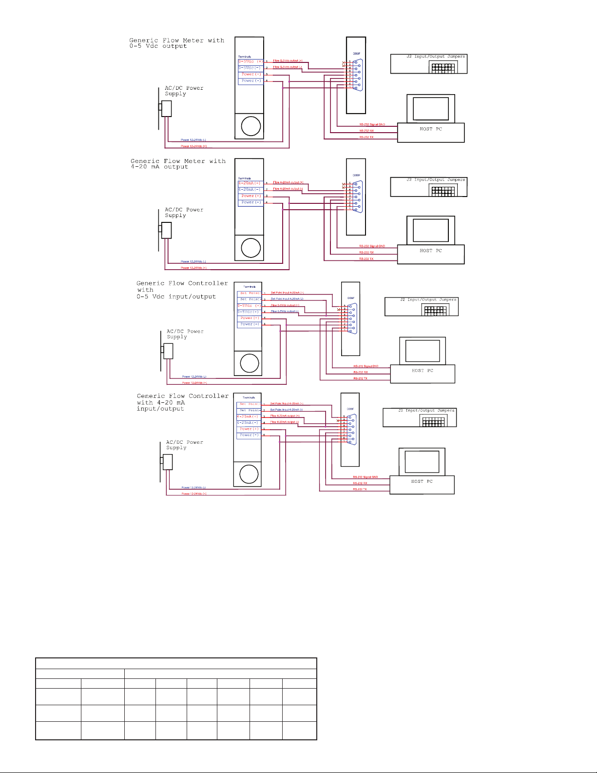
G
F
T2
G
F
T2
G
F
T2
G
F
T2
Figure 38: Connecting GFT2 to the Generic Flow Meter
GFT
2
GFT
2
GFT
2
GFT
2
Figure 39: Connecting GFT2 to the Generic Flow Controller
c) Input/Output Jumper Configuration
NOTE: The GFT2 device input/output jumpers were configured at the factory
according to the order. There is no need to change input/output
jumpers’configuration unless a different input is being used. Before applying
power and process signals, make sure the input/output jumpers are installed in
the correct position. See Table 9.
d) Parameters Configuration
The following parameters have to be configured
• Device Function (see Submenu “Device Function”). If GFT2 is connected to
flow controller, then “Controller” function has to be selected. If GFT2 is
connected to the flow meter, then “Meter” function has to be selected
• Full-Scale Range (see Submenu “Device Calibration”). Full-Scale Range
parameter must be set equal to the mated device full-scale flow rate in L/min.
• Fluid Std. Density (see Submenu “Device Calibration”). This parameter is
required only when mass-based engineering units are selected.
Input/Output Jumper Configuration Options for Generic Flow Meters and Controllers
GFT2
Output
0 to 5 VDC
4 to 20 mA
0 to 10 VDC
Input
0 to 5 VDC
4 to 20 mA
0 to 10 VDC
J2A
2 to 3
1 to 2
2 to 3
5 to 6
4 to 5
5 to 6
J2 Jumper Configuration
J2B
J2C
8 to 9
7 to 8
8 to 9
J2D
10 to 11
10 to 11
11 to 12
J2D
14 to 15
13 to 14
14 to 15
J2F
17 to 18
16 to 17
17 to 18
NOTE: If “Full-Scale Range”, “Device Function”, and “Fluid Std. Density”
parameters are not set properly, device may have erroneous reading and
unpredictable behavior
User may configure other parameters according to individual preferences and
application requirements.
Troubleshooting
Common Conditions
The GFT2 Totalizer Input/Output Flow Monitor/Controller was thoroughly
checked at numerous quality control points during and after manufacturing and
assembly operations. It was calibrated according to the input and output
configuration. It was carefully packaged to prevent damage during shipment. If
instrument is not functioning properly, please check for the following common
conditions:
• Are all cables connected correctly?
• Were the connector pin outs matched properly?
• Are J2 input/output jumpers configured correctly?
• Is the power supply correctly selected according to requirements?
When several devices are used, a power supply with appropriate current rating
should be selected. When interchanging with other manufacturers’ equipment,
cables and connectors must be carefully wired for correct pin configuration.
Page 17

umber
N
ndication
CD Display remains blank when unit is
L
1
powered up. Status LED is OFF.
LCD Displays flow reading, but 4 to 20
2
mA Set Point output signal does not
hange.
c
Fluid flows throught he flow
3
eter/controller, but the LCD Display
m
nd/or Totalizer reading does not
a
respond to the flow.
luid flows through the flow
F
4
meter/controller and LCD Display Flow
Rate reading responds to flow, but
otalizer reading is not changing.
T
rratic Flow Rate reading.
E
5
Totalizer reading is wrong.
6
LCD Displays flow reading, but
7
communication interface does not work.
The Device Diagnostic Alarm Event with
8
code 0 - "CPU Temp. High" is active.
The Device System Event with code D -
9
"Fatal Error" is active.
I
Likely Reason
ower Supply is bad, or polarity is reversed.
P
PC board is defective.
rong configuration of J2 Input/Output
W
umpers.
J
External loop is open, or load resistance is
more than 600 Ohm.
External loop is open, or load resistance is
more than 600 Ohm.
he fluid flow rate is below set Low Flow Cut-
T
Off value.
Wrong configuration of J2 Input/Output
Jumpers.
PC board is defective.
The fluid flow rate is below set "Totalizer #1
low Start" parameter value.
F
Totalizer mode is disabled.
otalizer Power On Delay parameter is set to
T
high value and Totalizer is disabled by
firmware.
rong configuration of J2 Input/Output
W
Jumpers.
FT2 "Full-Scale Flow" parameter value (in
G
L/min) is not equal to the mated device fullscale range.
GFT2 "Fluid Std. Density" parameter is not set
according to fluid being used and mass based
engineering units are selected.
Wrong configuration of J2 Input/Output
Jumpers.
GFT2 "Full -cale Flow" parameter value (in
L/min) is not equal to the mated device fullscale range.
Wrong host PC interface or wiring connection.
GFT2 has RS-485 interface but device
address does not match addressed used by
host PC.
MCU/PCB temperature is too high (overload).
Fatal Error (EEPROM or SRAM corrupted).
easure voltage on pins 2 and 1 of the DB9 interface terminal
M
onnnector. If voltage is out of specified range, then replace
c
power supply with a new one. If polarity is reversed (reading is
negative), make correct connection.
eturn device to factory for repair.
R
heck J2 jumper configuration (see Table 9).
C
Check for external connections to pins 5 and 6 of the DB9
nterface terminal connector. Make sure the loop resistance is
i
ess than 400 Ohm for 12 VDC power supply option and 900
l
Ohm for 24 VDC power supply option.
Using Key Pad, navigate to submenu "Device Diagnostic" and
elect submenu "Analog Output Value". Record the DAC counts
s
alues and consult the factory with findings.
v
Check settings for Low Flow Cut-Off value and make required
adjustment (see Submenu "Low Flow Cut-Off").
heck J2 input jumper configuration (see Table 9). If necessary,
C
ontact factory for additional help.
c
Using ESD precautions, measure voltage on pins 4 and 6 of the
DB9 interface terminal connector. If voltage correlates with flow
meter/controller output signal, check ADC counts. Using Key Pad,
avigate to Submenu "Device Diagnostic" and selet Submenu
n
"ADC Input Counts". Record the ADC counts values and consult
the factory with findings.
Check settings for "Totalizer #1 Flow Start" value and make
equired adjustment (see Submenu "Totalizer #1 Flow Start").
r
Check settings for "Totalizer #1 Mode" parameter. Make sure
otalizer Mode is set to "Enabled" (see Submenu "Totalizer #1
T
Mode").
heck settings for "Totalizer Power On Delay" (see Submenu
C
"Totalizer #1 Power On Delay"). If settings are too high, make
required adjustment.
heck J2 input jumper configuration (see Table 9). If necessary,
C
contact factory for additional help.
Check settings for "Full Scale Range" (see Submenu "Device
Calibration"). Full Scale Range parameter has to be set equal to
the mated device full scale flow rate in L/min.
Check settings for "Fluid Std. Density" (see Submenu "Device
Calibration"). This parameter is required only when mass-based
engineering units are selected.
Check J2 input jumper configuration (see Table 9). If necessary,
contact factory for additional help.
Check settings for "Full Scale Range" (see Submenu "Device
Calibration"). Full Scale Range parameter has to be set equal to
the mated device full scale flow rate in L/min.
Make sure interface type (RS-232 or RS-485) on the host PC is
the same as on the GFT2 device. Check communication wiring
connection according to "Digital Communication Interface
Connections".
Change GFT2 RS-485 address to match host PC software
settings.
Disconnect power from the GFT2. Make sure the ambient
temperature is within specified range (below 158°F or 70°C). Let
the device cool down for at least 15 minutes. Apply power to the
device and check Diagnostic Alarm Event. If overload connection
will be indicated again, the unit has to be returned to the factory
for repair.
Cycle the power on the GFT2. If System Event with code D
indicates again, the unit must be returned to the factory for repair.
Solution
Page 18

PPENDIX A
A
FT2 Totalizer Input/Output Flow Monitor/Controller EEPROM Variables
G
ata Type
ame
ndex
I
0
1
2
3
4
5
6
7
8
9
10
1
1
2
1
3
1
14
5
1
6
1
7
1
18
9
1
0
2
21
22
23
4
2
25
26
7
2
28
29
0
3
31
2
3
33
34
35
36
37
38
39
40
41
42
43
44
45
46
47
48
49
50
51
52
53
54
55
56
57
58
59
60
61
62
63
64
65
66
67
68
69
70
71
72
73
74
75
76
77
78
79
80
B
S
ModelNumber[20]
S
M
M
ManufReservedF7
ManufReservedF8
R
M
ManufReservedF4
ManufReservedF5
M
M
ManufReservedUI2
ManufReservedUI3
ManufReservedUI4
M
ManufReservedSI2
ManufReservedSI3
TimeSinceCalHr
T
DeviceFunction
BaudRate
A
F
UDUnitKfactor
U
U
KfactorMode
KfactorIndex
U
D
PSP_Mode
SetPointPFS
DiagEventLatchMask
Reserved3
Reserved4
OptOut1_Config
OptOut2_Config
GLCD_Mode
GLCD_Static_Mode
GLCD_AUTO_Mode_Mask
Cycle_Time
GLCD_Contrast
GLCD_Reserved
GLCD_LED_PWM
PSP_StepMasc
PSP_LoopMode
Out_Scale_mA
Out_Offset_mA
In_mA_Mode
In_mA_Reserved
In_Scale_mA
In_Offset_mA
OutScaleV
OutOffsetV
InScaleV
InOffsetV
F_AlarmMode
F_LowAlarmPFS
F_HiAlarmPRS
F_AlmDelay
F_AlarmLatch
F_AlarmSpare
Total1_Mode
Total1_Config
Total1_FlowStart
Total1_VolStop
Total1_PowOnDelay
Total1_ValueLock
Total1_Volume_BkUp
Total1_AutoReset
Total1_AtoResetDelay
Total1_Reserved
Total2_Mode
Total2_Config
Total2_FlowStart
Total2_VolStop
Total2_PowOnDelay
Total2_Volume_BkUp
N
lankEEPROM[10]
erialNumber[20]
oftwareVer[10]
anufReservedF1
anufReservedF2
eservedText[12]
anufReservedF3
anufReservedF6
anufReservedUI1
anufReservedSI1
ProtectionCode
ddress485
lowUnits
DUnitTimeBase
DUnitDensity
serDefKfactor
iagEventMask
D
char[10]
char[20]
har[20]
c
har[10]
c
loat
f
float
loat
f
loat
f
char[12]
float
loat
f
loat
f
float
uint
int
u
int
u
uint
int
int
nt
i
float
uint
uint
int
u
char[4]
int
float
nt
i
uint
uint
uint
loat
f
uint
uint
float
uint
float
float
uint
uint
uint
uint
uint
uint
uint
uint
uint
uint
uint
float
float
uint
uint
float
float
float
float
float
float
uint
float
float
uint
uint
uint
uint
uint
float
float
uint
uint
float
uint
uint
uint
uint
uint
float
float
uint
float
Do not modify. Table Revision [PROTECTED]
Serial Number [PROTECTED]
odel Number [PROTECTED]
M
irmware Version [PROTECTED]
F
anufacture Specific float data [PROTECTED]
M
Manufacture Specific float data [PROTECTED]
anufacture Specific float data [PROTECTED]
M
anufacture Specific float data [PROTECTED]
M
Reserved for Manufacture Specific Text Info [PROTECTED]
Manufacture Specific float data [PROTECTED]
anufacture Specific float data [PROTECTED]
M
anufacture Specific float data [PROTECTED]
M
Manufacture Specific float data [PROTECTED]
Manufacture Specific float data [PROTECTED]
anufacture Specific float data [PROTECTED]
M
anufacture Specific float data [PROTECTED]
M
Manufacture Specific float data [PROTECTED]
Manufacture Specific float data [PROTECTED]
Manufacture Specific float data [PROTECTED]
anufacture Specific float data [PROTECTED]
M
Time elapsed since last calibration in hours
Program Parameters Protection Code [0-255]
Device Function: 0-FlowMeter,1-FlowController
omm. Interface Baud Rate Index [0-7]
C
Two hexadecimal characters address for RS485 only [01-FF]
Current Units of Measure [0-46]
Current Units of Measure [0-46]
ser defined Unit Time base index:[0-3]
U
User defined Unit use density flag 1-'Y', 0-'N'
o-Disabled, 1-Internal, 2-User Defined
Internal K-Factor Index [0-21]
ser defined K-Factor
U
Mask for Diagnostic Events: Clear bit -> mask
Mode for Program SP: 0-disabled, 1-enabled
Set Point value in %FS fraction notation [0.0 - 1.1]
Diagnostic Events Latch Mask register: Clear bit -> mask
Device General Reserved Settings
Device General Reserved Settings
Optical Output #1 Configuration (function)
Optical Output #2 Configuration (function)
Main Process screen mode: 0-Static, 1-Dynamic
Type of the static LCD screen: [0-3]
Type of the AUTO LCD screen: keeps mask for each variable
Time in seconds for each screen to be displayed in Dynamic mode
GLCD Contrast settings [1 - 16]
GLCD reserved settings
GLCD LED backlight PWM Duty cycle [1 - 16]
GLCD reserved settings
Program SP Loop mode:0-disabled, 1-enabled
Analog 4-20 mA Out Scale
Analog 4-20 mA Out Offset
Reserved Input parameter
Reserved Input parameter
Analog 4-20 mA Out Scale
Analog 4-20 mA Out Offset
Flow Analog 0-5/0-10 VDC Out Scale
Flow Analog 0-5/0-10 VDC Out Offset
Flow Analog 0-5/0-10 VDC Input Scale
Flow Analog 0-5/0-10 VDC Input Offset
Flow Alarm Mode (0=Disabled, 1=Enabled)
Low Flow Alarm in PFS [0-1.0 fraction notation %F.S.]
High Flow Alarm in PFS [0-1.0 fraction notation %F.S.]
Delay in seconds 0-3600 for Flow Alarm action
Flow Alarm Latch
Flow Alarm Spare settings
Totalizer #1 mode (0-Disabled, 1-Enabled)
Totalizer #1 configuration (0-Count Up)
Start tot. at flow [0-1.0 fraction notation %F.S.]
Limit volume in %s, 0 = disable
Totalizer #1 power on delay in second [0-3600]
Lock Totalizer #1 value (0-can be reset, 1-can not be reset)
Totalizer #1 backup volume in %s (saved every 6 minutes)
Reset Total. Volume value when Totalizer value equals Limit volume 0 - No, 1 - Yes
Delay in seconds before AutoReset will reset Totalizer#1 volume reading to zero [0-3600]
Totalizer#1 reserved
Totalizer#2 mode: (0-Disabled, 1-Enabled)
Totalizer#2 configuration (0-Count Up, 1-Count Down)
Start tot. at flow [0-1.0 fraction notation %F.S.]
Limit volume in %s, 0 = disable
Totalizer#2 power on delay in seconds [0-3600]
Totalizer#2 backup volume in %s (saved every 6 minutes)
N
otes
Page 19

81
82
3
8
4
8
5
8
86
7
8
8
8
89
90
1
9
2
9
93
94
5
9
6
9
97
98
99
00
1
101
102
103
04
1
105
106
107
08
1
09
1
110
111
12
1
113
14
1
115
16
1
117
118
119
120
121
122
123
124
125
126
127
128
129
130
131
132
133
134
135
136
137
138
139
140
141
142
143
144
145
146
147
148
149
150
151
152
153
154
155
156
157
158
159
160
161
162
163
ndex
I
ame
N
otal2_ReloadVolStop
T
Total2_ReloadDelay
Total2_10SecBackUp
otal2_Reserved
T
low_Pulse_Mode
F
PulseFlowStart
Units_Per_Pulse
ctive_Low_Time
A
low_Pulse_Reserved
F
FlowCondMode
Flow_NRF_NSample
low_NRF_ErrLimit
F
Flow_NRF_TimeLimit
Flow_Damping
Flow_Window
lowLinearizer
F
low_SC_Reserved
F
FlowTbl[0]. FlowPFSIn
FlowTbl[0]. FlowPFSOut
lowTbl[1]. FlowPFSIn
F
lowTbl[1]. FlowPFSOut
F
FlowTbl[2]. Flow PFSIn
FlowTbl[2]. Flow PFSOut
lowTbl[3]. Flow PFSIn
F
lowTbl[3]. Flow PFSOut
F
FlowTbl[4]. FlowPFSIn
FlowTbl[4]. FlowPFSOut
lowTbl[5]. FlowPFSIn
F
lowTbl[5]. FlowPFSOut
F
lowTbl[6]. FlowPFSIn
F
lowTbl[6]. FlowPFSOut
F
FlowTbl[7]. FlowPFSIn
lowTbl[7]. FlowPFSOut
F
lowTbl[8]. FlowPFSIn
F
FlowTbl[8]. FlowPFSOut
FlowTbl[9]. FlowPFSIn
FlowTbl[9]. FlowPFSOut
FlowTbl[10]. FlowPFSIn
FlowTbl[10]. FlowPFSOut
MDSerialNumber
MeterFSRange
LowFlowCutOff
FlowPowerUpDelay
Density
FluidName[20]
CalibratedBy[20]
CalibratedAt[20]
DateCalibrated[12]
DateCalibratedDue[12]
UserTagName
PSPTbl[0].PFS
PSPTbl[0].Time
PSPTbl[1].PFS
PSPTbl[1].Time
PSPTbl[2].PFS
PSPTbl[2].Time
PSPTbl[3].PFS
PSPTbl[3].Time
PSPTbl[4].PFS
PSPTbl[4].Time
PSPTbl[5].PFS
PSPTbl[5].Time
PSPTbl[6].PFS
PSPTbl[0].Time
PSPTbl[7].PFS
PSPTbl[7].Time
PSPTbl[8].PFS
PSPTbl[8].Time
PSPTbl[9].PFS
PSPTbl[9].Time
PSPTbl[10].PFS
PSPTbl[10].Time
PSPTbl[11].PFS
PSPTbl[11].Time
PSPTbl[12].PFS
PSPTbl[12].Time
PSPTbl[13].PFS
PSPTbl[13].Time
PSPTbl[14].PFS
PSPTbl[14].Time
PSPTbl[15].PFS
PSPTbl[15].Time
EEMagicNumber
Data Type
int
u
int
u
int
u
uint
uint
loat
f
loat
f
uint
uint
int
u
int
u
float
uint
int
u
int
u
uint
uin
loat
f
loat
f
float
float
loat
f
loat
f
loat
f
float
loat
f
loat
f
float
float
loat
f
float
float
loat
f
float
loat
f
loat
f
float
float
float
float
float
float
float
float
float
float
float
float
float
float
float
float
float
float
float
float
float
float
float
float
float
float
float
float
float
float
float
float
float
float
float
float
float
float
float
float
float
float
float
float
float
float
uint
eload VolStop value when Totalizer reading counts down to zero 0 - No, 1 - Yes
R
elay in seconds before Reload VolStop value when Totalizer reading counts down to zero [0-3600]
D
nable or Disable every 10 seconds EEPROM backup (reserved for future version release)
E
Totalizer #2 reserved
Flow Pulse Output Mode (0=Disabled, 1=Enabled)
tart pulse output at flow [0-1.0 fraction notation %F.S.]
S
nits per pulse scaling
U
Number of ms output will be activated when pulse is developed
Pulse Output Reserved
- No conditioning, 1 - NRF, 2 - Running Average
0
low NRF Number of Samples [1 - 32]
F
Flow NRF Error Value [0.05 10.0] %F.S. (FN)
Flow NRF Time Interval [0-199], 0-disabled
eading Damping 0-500 ms
R
low running average window [0-32] 0 - disable
F
Flow Linearizer: On (1), off (0)
Flow Signal Conditioner reserved
low Linearizer Index 0 PFS In (must be 0.0)
F
low Linearizer Index 0 PFS Out (must be 0.0)
F
Flow Linearizer Index 1 PFS In [0.0 - 1.0]
Flow Linearizer Index 1 PFS Out [0.0 - 1.0]
low Linearizer Index 2 PFS In [0.0 - 1.0]
F
low Linearizer Index 2 PFS Out [0.0 - 1.0]
F
low Linearizer Index 3 PFS In [0.0 - 1.0]
F
Flow Linearizer Index 3 PFS Out [0.0 - 1.0]
low Linearizer Indes 4 PFS In [0.0 - 1.0]
F
low Linearizer Indes 4 PFS Out [0.0 - 1.0]
F
Flow Linearizer Indes 5 PFS In [0.0 - 1.0]
Flow Linearizer Indes 5 PFS Out [0.0 - 1.0]
low Linearizer Indes 6 PFS In [0.0 - 1.0]
F
Flow Linearizer Indes 6 PFS Out [0.0 - 1.0]
Flow Linearizer Indes 7 PFS In [0.0 - 1.0]
low Linearizer Indes 7 PFS Out [0.0 - 1.0]
F
Flow Linearizer Indes 8 PFS In [0.0 - 1.0]
low Linearizer Indes 8 PFS Out [0.0 - 1.0]
F
low Linearizer Indes 9 PFS In [0.0 - 1.0]
F
Flow Linearizer Indes 9 PFS Out [0.0 - 1.0]
Flow Linearizer Indes 10 PFS In [0.0 - 1.0]
Flow Linearizer Indes 10 PFS Out [0.0 - 1.0]
Serial Number for Mated Device
Device FS range in Std. L/min
Must be between [0 and 0.1] fraction %F.S. notation [0-1.0]
Flow Power Up delay [0-1200] sec.
Fluid Density g/L
Name of the Fluid used for Calibration
Name of person meter was calibrated by
Name of the Calibration Lab
Calibration date
Date Calibration due
User Defined Device Tag Name or Number
PSP Table Index 0 Set Point PFS (0.0-1.0)
PSP Table Index 0 Time (sec)
PSP Table Index 1 Set Point PFS (0.0-1.0)
PSP Table Index 1 Time (sec)
PSP Table Index 2 Set Point PFS (0.0-1.0)
PSP Table Index 2 Time (sec)
PSP Table Index 3 Set Point PFS (0.0-1.0)
PSP Table Index 3 Time (sec)
PSP Table Index 4 Set Point PFS (0.0-1.0)
PSP Table Index 4 Time (sec)
PSP Table Index 5 Set Point PFS (0.0-1.0)
PSP Table Index 5 Time (sec)
PSP Table Index 6 Set Point PFS (0.0-1.0)
PSP Table Index 6 Time (sec)
PSP Table Index 7 Set Point PFS (0.0-1.0)
PSP Table Index 7 Time (sec)
PSP Table Index 8 Set Point PFS (0.0-1.0)
PSP Table Index 8 Time (sec)
PSP Table Index 9 Set Point PFS (0.0-1.0)
PSP Table Index 9 Time (sec)
PSP Table Index 10 Set Point PFS (0.0-1.0)
PSP Table Index 10 Time (sec)
PSP Table Index 11 Set Point PFS (0.0-1.0)
PSP Table Index 11 Time (sec)
PSP Table Index 12 Set Point PFS (0.0-1.0)
PSP Table Index 12 Time (sec)
PSP Table Index 13 Set Point PFS (0.0-1.0)
PSP Table Index 13 Time (sec)
PSP Table Index 14 Set Point PFS (0.0-1.0)
PSP Table Index 14 Time (sec)
PSP Table Index 15 Set Point PFS (0.0-1.0)
PSP Table Index 15 Time (sec)
Number used to verify EEPROM integrity
Notes
Page 20

PPENDIX B
A
nternal K-Factors Table
I
ensity
I
1
2
3
4
5
6
7
8
9
10
1
1
2
1
13
4
1
5
1
6
1
17
18
9
1
0
2
21
22
ndex
ctual Gas
A
rgon Ar
A
Arsine AsH3
oron Triflouride BF3
B
romine Br2
B
cetylene D2H2
A
Cyanogen C2N2
ethane CH4
M
hlorine Cl
C
Carbon Dioxide CO
C
C
2
arbonyl Fluoride CoF
arbonyl Sulfide COS
Carbon Disulfide CS
luorine F2
F
Hydrogen H
elium He
H
itrous Oxide
N
mmonia NH3
A
2
Neon NE
Nitric Oxide O2
ulfur Dioxide SO2
S
Xenon Xe
2
2
2
Factor
K
Relative to N
.4573
1
.6735
0
0.5082
0.8083
.5829
0
.61
0
0.7175
0.86
.7382
0
.5428
0
0.6606
0.6026
.9784
0
.0106
1
1.454
0.7128
.731
0
.46
1
.99
0
0.9926
0.69
.44
1
2
C
[Cal/g]
.1244
0
.1167
0
.1778
0
0.0539
.4036
0
.2613
0
.5328
0
0.114
.2016
0
.171
0
.1651
0
0.1428
0.1873
.419
3
.241
1
0.2088
0.492
.246
0
0.2328
0.2193
0.1488
0.0378
D
p
[g/L]
.782
1
.478
3
.025
2
7.13
.162
1
.322
3
.715
0
3.163
.964
1
.945
2
.68
2
3.397
1.695
.0899
0
.1786
0
1.964
0.76
.9
0
1.339
1.427
2.858
5.858
APPENDIX C
GFT2 ASCII Commands Set
S-232/RS-485
R
The standard GFT2 comes with an RS-232 interface. The protocol described below
allows communication with the unit using either a custom software program or a
“dumb” terminal. All values are set as printable ASCII characters. For RS-232
interface, the start character and two characters of address have to be omitted. For
the RS-485 interface, the start character is always ‘!’, and two characters of
address follow. The command string is terminated with a carriage return (line feeds
are automatically stripped out by the GFT2):
*Default address for all units is set to 11 hex. Do not submit start character
*
nd device address for RS-232 option.
a
everal examples of commands follow. All assume that the GFT2 has been
S
configured for address 18 (12 hex) on the RS-485 bus:
1. To get a flow reading: !12,F<CR>
he device will reply: !12,50.0<CR>
T
. To get current Flow Alarm status: !12,A,S<CR>
2
he device will reply: !12,AS:N<CR>
T
Assuming the flow is at 50.0% FS)
(
(Assuming no alarm conditions)
3. To get Totalizer#1 reading: !12,T,1,R<CR>
The device will reply: !12,T1R:93.5<CR>
Assuming the Totalizer#1 reading
(
s 93.5)
. Set the flow high and low alarm limit to 90% and 10% of full-scale flow rate:
4
i
!12,A,C,90.0,10.0<CR>
The device will reply: !12,AC:90.0,10.0<CR>
RS-485 !<Addr>,<Cmd>,Arg1,Arg2,Arg3,Arg4<CR> Example: !12,F<CR>
RS-232 Cmd,Arg1,Arg2,Arg3,Arg4<CR> Example: F<CR>
Where: ! Start character **
Addr RS-485 device address in the ASCII
representation of hexadecimal (00 through FF
are valid). **
Cmd The one or two character command from the
table below.
Arg1 to Arg4 The command arguments from the table below.
Multiple arguments are comma delimited.
CR Carriage return character
Page 21

Page 22
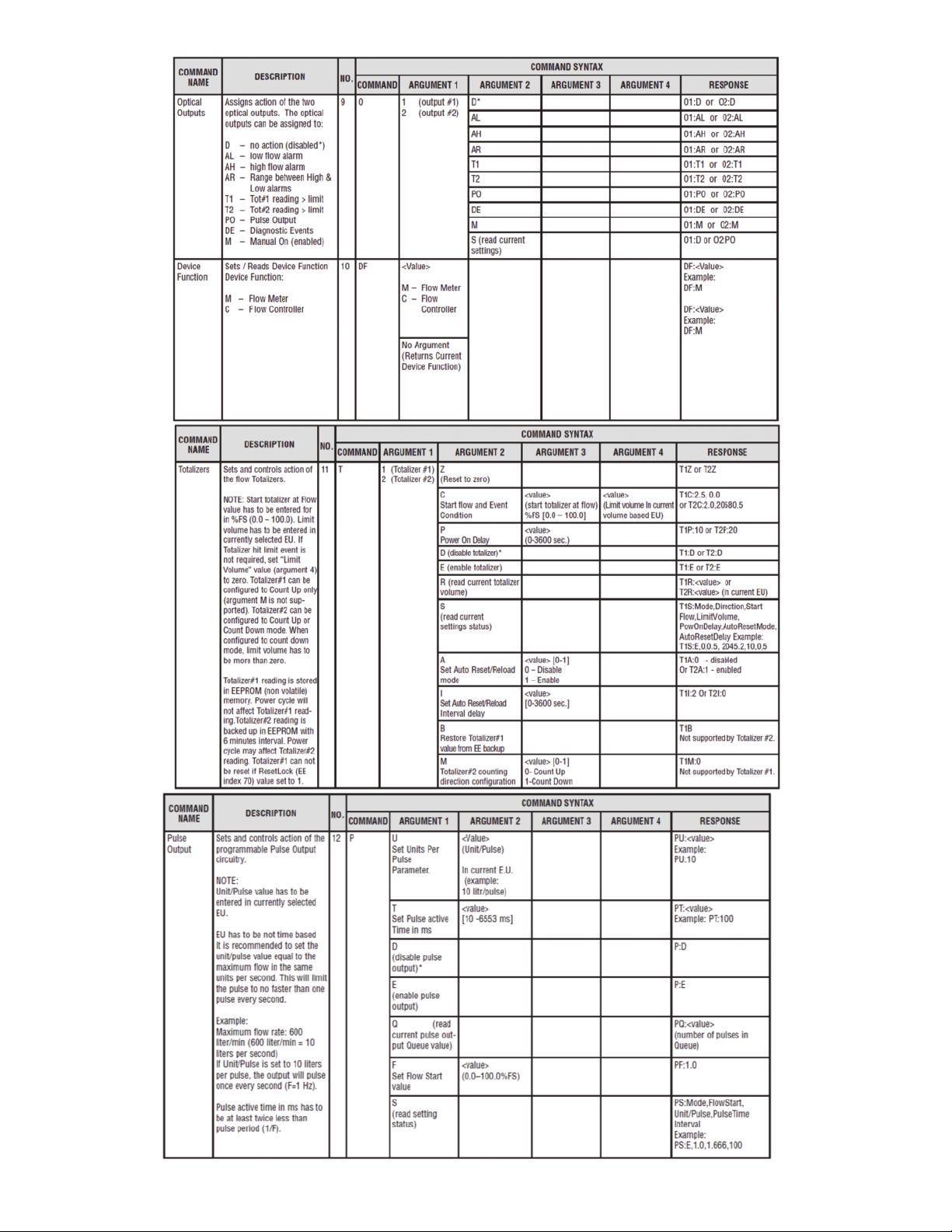
Page 23

Page 24
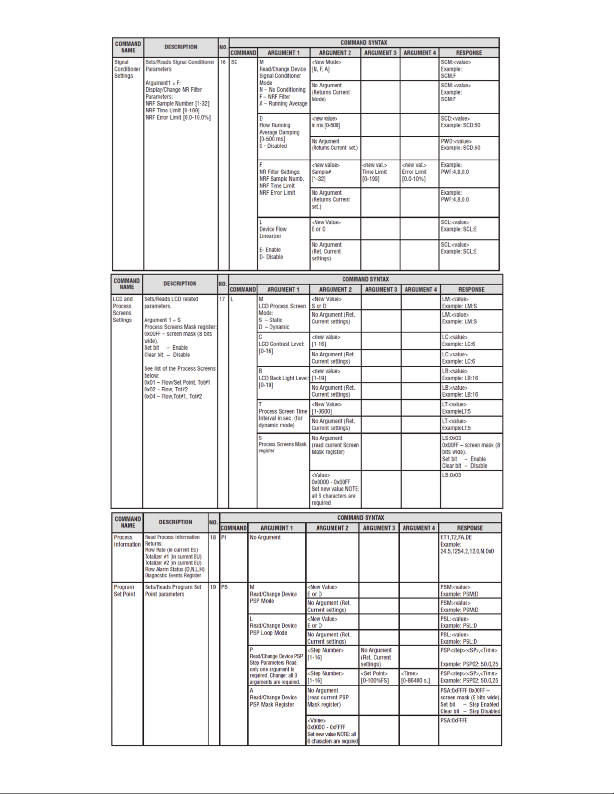
Page 25
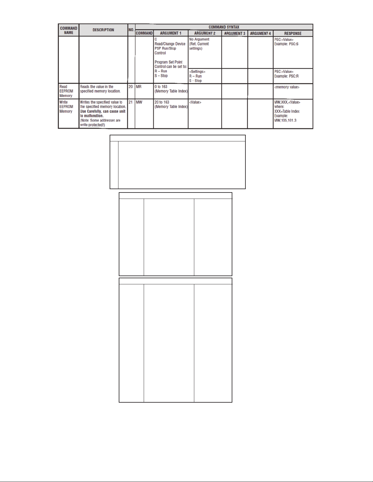
UART Error Codes
Not supported command or back door is not enabled
1
Wrong number of arguments
2
ddress is out of range (MR or MW commands)
A
3
rong number of the characters in the argument
W
4
Attempt to alter Write Protected area in the EEPROM
5
roper command or argument not found
P
6
Wrong value of the argument
7
eserved
R
8
anufacture specific into EE KEY (wrong key or key is disabled)
M
9
Diagnostic and System Events Codes and Bit Position
Code
0
1
2
3
4
5
6
7
8
9
A
B
C
D
Index
1
2
3
4
5
6
7
8
9
10
11
12
13
14
15
16
17
18
19
20
21
22
Event Description
CPU Temp. High
High Flow Alarm
Low Flow Alarm
Range betwen H-L
Tot#1 > Limit
Tot#2 > Limit
OptPulse Queue
Flow OverLimit
Vcc OutOfRange
SerComm. ERROR
EEPROM ERROR
Power on Event
Password Event
Fatal Error
Internal K-Factor Table List
Gas
Ar
AsH3
BF3
Br2
C2H2
C2N2
CH4
Cl2
CO2
COF2
COS
CS2
F2
H2
He
N20
NH3
NE
NO
O2
SO2
Xe
Bit Position
0x0001
0x0002
0x0004
0x0008
0x0010
0x0020
0x0040
0x0080
0x0100
0x0200
0x0400
0x0800
0x1000
0x2000
K-Factor
1.4573
0.6735
0.5082
0.8083
0.5829
0.6100
0.7175
0.8600
0.7382
0.5428
0.6606
0.6026
0.9784
1.0106
1.4540
0.7128
0.7310
1.4600
0.9900
0.9926
0.6900
1.4400
Page 26

PPENDIX D
A
echanical Drawings
M
APPENDIX E
Circuit Layout Diagrams
Circuit Layout Top
ircuit Layout Bottom
C
irror
M
APPENDIX F
Warranty
FT2 Totalizer Input/Output Flow Monitor/Controller is warranted against parts and
G
orkmanship for a period of one year from the date of purchase. It is assumed that
w
quipment selected by the customer is constructed of materials compatible with the
e
environment in which the GFT2 is being used. Proper selection is the responsibility
of the customer. It is understood that power supply voltage and external signals
should not exceed allowable limits provided in this manual, and it is deemed the
responsibility of the customer that only operators with basic knowledge of the
quipment and its limitations are permitted to control and operate the equipment
e
overed by this warranty. Anything to the contrary will automatically void Dwyer ’s
c
iability and the provisions of this warranty. Defective products will be repaired or
l
replaced at no charge solely at the discretion of Dwyer. Shipping charges are borne
by the customer. This warranty is void if the equipment is damaged by accident or
misuse, or has been repaired or modified by anyone other than Dwyer or factory
authorized service facility. This warranty defines the obligation of Dwyer and no
other warranties expressed or implied are recognized.
MAINTENANCE/REPAIR
Upon final installation of the Series GFT2 no routine maintenance is required. The
Series GFT2 is not field serviceable and should be returned if repair is needed.
Field repair should not be attempted and may void warranty.
WARRANTY/RETURN
Refer to “Terms and Conditions of Sales” in our catalog and on our website. Contact
customer service to receive a Return Goods Authorization number before shipping
the product back for repair. Be sure to include a brief description of the problem
plus any additional application notes.
CAUTION
This product is not intended to be used in life support
applications!
©Copyright 2012 Dwyer Instruments, Inc. Printed in U.S.A. 9/12 FR# RA-444038-00
DWYER INSTRUMENTS, INC.
Phone: 219/879-8000 www.dwyer-inst.com
P.O. BOX 373 • MICHIGAN CITY, INDIANA 46360, U.S.A. Fax: 219/872-9057 e-mail: info@dwyer-inst.com
 Loading...