

Page 1
Bulletin # F-41-FS
Series FS Flowmeter with Limit Switch
Specifications - Installation and Operating Instructions
DESCRIPTION
Industrial
rugged, low cost, and simple to install. The Series FS
offers visual flow rate indication and an adjustable flow
alarm to open or close AC electrical circuits, trigger
warning lights, or activate other process control
equipment. Operating within ±5% of full scale accuracy,
the Series FS can be installed vertically or horizontally
without installing any special plumbing. The Series FS is
constructed of high impact resistant polysulfone. This
series offers excellent structural integrity against operating
pressures up to 325 psi (22.4 bar) for liquids and 125 psi
(8.6 bar) for gases. The Series FS can withstand fluid
temperatures up to 250°F (121°C) and is compatible with a
wide range of chemicals.
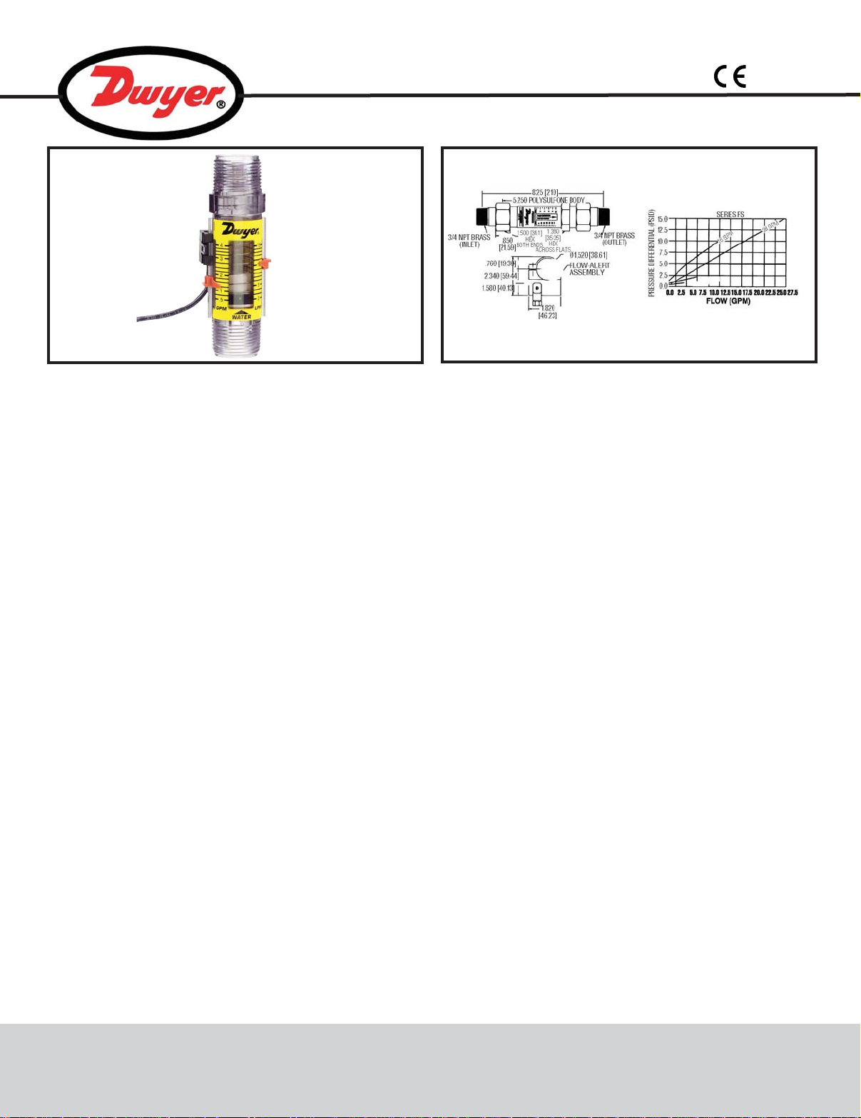
Direct-Reading Series FS Flowmeters are
OPERATING PRINCIPLE
The Series FS is a piston-type variable area flow meter
that uses a sharp-edged annular orifice formed between
an open-centered piston and tapered metering cone. the
piston is held in a “no flow” position at the base of the
cone by a precision retention spring. Flow through the
meter creates a pressure differential across the piston
orifice, moving the piston against the spring. Piston
movement and orifice area are proportional to the rate of
flow. Therefore, the greater the rate of flow, the further the
piston moves along the tapered metering cone. The flow
rate is measured by the viewing the red indicator ring
mounted on the piston relative to a graduated flow scale
affixed to the outer surface of the flow meter body.
MECHANICAL INSTALLATION
CAUTION: DO NOT OVER TIGHTEN THE THREADS ON
THE PLASTIC BODY. Overtightening the NPT threads may
cause fracturing of the plastic flowmeter body. The
flowmeter is constructed of polysulfone and remains
stable to 210°F (99°C). DO NOT EXPOSE FLOWMETER
PHYSICAL DATA
Accuracy: ±5% Full Scale.
Repeatability: 1.0%.
Set Point: Adjustable 0 to
100% FS.
Pressure Limits: 325 psi (22.4
bar)
Temperature Limits: 250°F
(121°C).
Supply Voltage: 115 VAC, 140
VAC max.
TO OPEN FLAMES OR EXCESSIVE HEAT. The meter may
melt, crack, or distort. Some pipe dope formulas will react
adversely with polysulfone. Use Teflon
material is necessary.
The Series FS can be mounted in any plane of orientation.
Horizontal or vertical mounting does not effect flowmeter
accuracy. The inlet and outlet of the flowmeter should be
aligned, particularly when high temperature, high
pressure, or a combination of both may be encountered.
Install the flowmeter in the direction of the indicating
arrow on the scale. The Series FS Flowmeter does not
require lengths of straight pipe at the inlet, or outlet, to
stabilize flow through the meter. These meters can
tolerate particles that normally will jam other flow controls.
If large amounts of particulates are encountered, a 200
mesh or 74 million micron filter is recommended.
A separate four conductor female connector is supplied
with the limit switch assembly. The connector must be
disassembled to solder wired onto it. See Figure 1. the
Connector has four solder lugs labeled 1, 2, 3, and 4.
Te rminals 3 and 4 are not used. It should be noted before
reassembly, which wire is connected to which solder plug.
Color coding or labeling the wires is advised. Secure
On-State Current: 0.02 to 1.0
A AC.
Connections: 1˝ male NPT
Polysulfone or
Brass.
Flow Scale: Calibrated at 1.0
specific gravity @ 70°F (21°C).
Wetted Materials: Polysulfone
body, Barium Ferrite, Stainless
Steel spring and retaining
rings.
3
/4˝ male NPT
®
tape as if sealing
DWYER INSTRUMENTS, INC.
P.O. BOX 373 • MICHIGAN CITY, INDIANA 46361, U.S.A. Fax: 219/872-9057 e-mail: info@dwyer-inst.com
Phone: 219/879-8000 www.dwyer-inst.com
Page 2
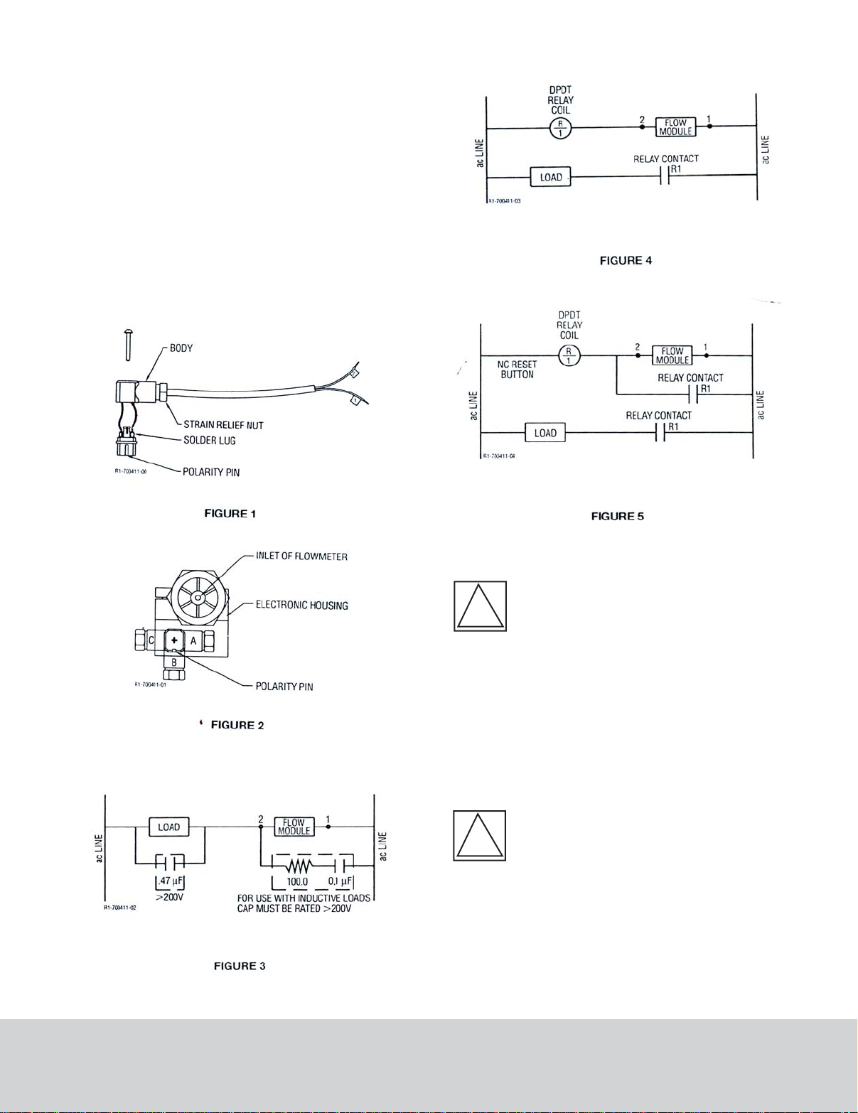
wires to solder lugs and determine the orientation A, B, or
!
!
C, snap the connector back together, pull excess wires
out of strain relief, and tighten strain nut. Plug into electric
housing and secure with screw.
ELECTRICAL INSTALLATION
The module can only switch loads that consume between
2.5 and 90 watts, or have 5000Ω to 150Ω impedence
respectively. If the load draws less than 2.5 watts, a 0.47
uF loading capacitor is required. This capacitor will
increase the power consumption and ensure complete
conduction. See Figure 3. Wiring according to Figure 3
will provide conduction over 15-20% of full scale, above
or below the flow rate set point. For loads greater than 90
watts, see Figures 4 and 5.
CAUTIONS
WARNING: Due to incompatibility,
Polysulfone flow meters SHOULD
NOT be used for monitoring the
following fluids: ACETONE, ALCOHOL,
BENZENE, CARBON DISULFIDE, FREON 11,
KEROSENE, LIQUID PROPANE, NAPHTHA,
AND PERCHLOROETHYLENE.
Other chemicals may also be incompatible with
Polysulfone. When in doubt, the meter should be tested in
a non-critical application under low pressure conditions to
determine compatibility. Also note that some chemicals
become more aggressive when heated. An acceptable
application may become unsafe at elevated temperatures.
CAUTION: These flowmeters are unidirectional devices. The piston acts as a check
valve to block flow in the reverse direction,
causing an excessive pressure differential
which could result in damage to internal
components.
DWYER INSTRUMENTS, INC.
P.O. BOX 373 • MICHIGAN CITY, INDIANA 46361, U.S.A. Fax: 219/872-9057 e-mail: info@dwyer-inst.com
Phone: 219/879-8000 www.dwyer-inst.com
Page 3
CAUTION: Consult the factory before using
!
any polysulfone meters to monitor the
following fluids: AMMONIA, ETHYLENE
GLYCOL 50/50, PHOSPHATE ESTER,
PHOSPHATE ESTER BASE, PHOSPHORIC
ACID.
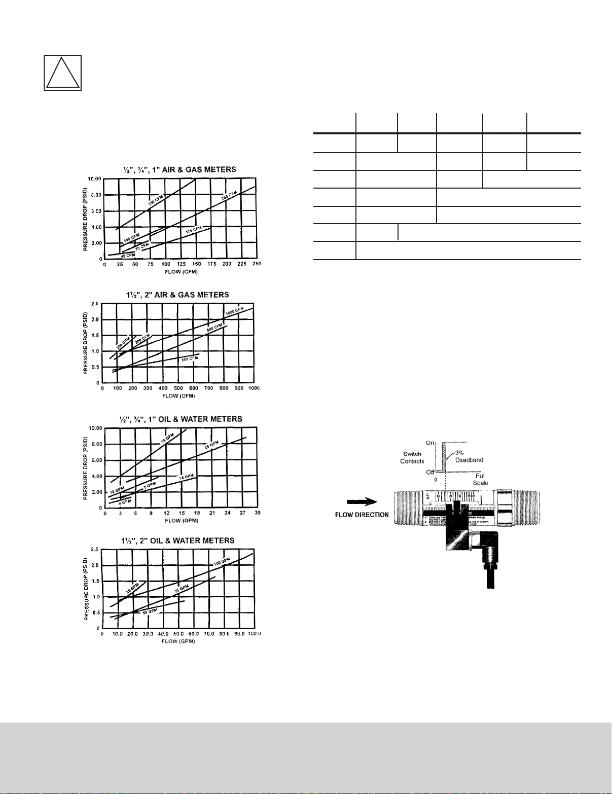
PRESSURE DROP
FLOW-ALERT SWITCH OPTIONS
NOTE: All flow-alert switches are magnetically triggered.
Magnets cannot be added to the basic flow meter so it
is not possible to add a switch to the basic meter if it
was not originally ordered with the switching magnet.
SWITCH SPECIFICATIONS
Specifications AC Latching DC Latching
Operating
Voltage
Operating
Current
Contact
Rating
Operating
Tem p .
Cable
Certification
Enclosure
Rating
115 VAC ±10%
1A @ 30 VDC 0.5 @125 VAC
32 to 158°F (0 to 70 °C)
N/A
10-30 VDC
25 mA max
Resistive Load
Not Included
Reed Switch
Form-A (N.O.)
1A @ 200 VDC
Resistive Load
NEMA 12 &13 (IP65)
Reed Switch
Form-B (N.C.)
N/A
N/A N/A
32 to 250°F (0 to 125 °C)
3 ft., 24 ga 2 conductor PVC Jacket
Reed Switch
Form-C (SPDT)
N/A
0.25A @ 175 VDC
Resistive Load
CE
N/A
N/A
FLOW-ALERT LATCHING LIMIT SWITCH
The AC and DC powered low alert modules consist of
relay circuit housed in a sealed polypropylene enclosure.
The modules have a normally open dry relay contact that
can be used to directly control alarms, warning lights, and
relays or can be used to interface to a PLC. The relay will
be latched on as the magnet inside the flow meter passes
by the module and remained latched on until the magnet
passes in the other direction or power is interrupted (See
Figure 5). The set point is adjustable from 0 to 100% of
full scale. Flow meters can be equipped with one latching
limit switch, either AC or DC.
Figure 5
Latching Switches
FLOW-ALERT REED LIMIT SWITCH
The reed switch alert modules are available in three
forms. They are: Form A (Normally Open), Form B
(Normally Closed), and Form C (SPDT). Reed switches are
housed in a sealed polypropylene enclosure for
environmental protection. the reed switch modules do not
provide a latching function like the AC and DC powered
units. When the magnet inside the flow meter comes
within proximity of the module, the reed switch will
DWYER INSTRUMENTS, INC.
Phone: 219/879-8000 www.dwyer-inst.com
P.O. BOX 373 • MICHIGAN CITY, INDIANA 46361, U.S.A. Fax: 219/872-9057 e-mail: info@dwyer-inst.com
Page 4

change state (See Figure 6). The set point is adjustable
from 0 to 100% of full scale. Two reed switch flow alerts
may be installed on a single flow meter but one must be
set for activation on increasing flow and the second must
be set for activation on decreasing flow.
Figure 6
Reed Switches
DC Switch
Figure 8
AC Switch
Latching Flow-Alert Switch Installation,
Operation and Adjustment
1. Install the switch on the flow meter by placing the
adjustment arms over the serated rail from the rear of the
meter by pushing down. The direction of the connector
and cable assembly indicate whether the switch will
activate on increasing flow, connector and cable pointing
up, or on decreasing flow, connector cable pointing down.
(See Figure 7.)
2. The connector has four solder lugs labeled: 1, 2, 3 and 4.
Soldering wires to the terminals first requires disassembly of
the connector as shown in Figure 8. Figure 9 depicts the
specific wiring pinouts for each style of latching switch. It
should be noted BEFORE reassembly which wire is
connected to which solder lug. Color coding or labeling the
wires is advised.
Pin
Function
1
Relay (NO)
2
DC +
3
Relay Common
4
DC -
Figure 9
Pin
Function
1
Relay (NO)
2
AC Supply
3
Relay Common
4
AC Supply
AC - WIRING CONFIGURATIONS
Warning: All wiring should be made in
accordance with the National Electrical Code
and must conform to any applicable state and
!
local codes.
3. After securing the wires to the solder lugs, a
determination of, “Which direction should the body of the
connector face?” needs to be made. Before snapping the
conductors back into the connector body, see Figure 10.
Figure 7
Figure 10
1 - AC Conventional Connection (Figure 11):
Note1: Load must be within specified contact rating range. 1 A
@ 30 VDC/500 mA @ 125 VAC.
4. After selecting direction A, B, or C, snap connector back
together, pull the excess wire out of the strain relief, and
tighten the strain relief nut.
DWYER INSTRUMENTS, INC.
P.O. BOX 373 • MICHIGAN CITY, INDIANA 46361, U.S.A. Fax: 219/872-9057 e-mail: info@dwyer-inst.com
Phone: 219/879-8000 www.dwyer-inst.com
Figure 11
Page 5
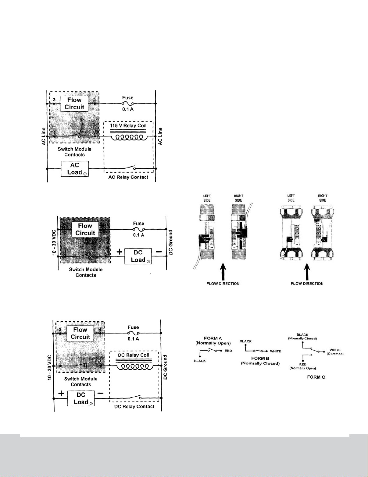
2 - AC Conventional Secondary Connections
(Figure 12):
Figure 12 demonstrates a secondary (slave) relay with a
115 VAC coil integrated with the AC switch module. This
combination allows switching of loads up to the rating of
the relay contacts.
3 - DC Conventional Connection (Figure 13):
Figure 12
Operation, and Adjustment
Warning: All wiring should be made in accordance with
the National Electrical Code and must conform to any
applicable state and local codes.
Figure 13 depicts the correct switch orientation to ensure
secure engagement of the adjustment locking mechanism.
The drawing assumes the flow scale points to the front.
1) Install the switch on the flow meter by placing the
adjustment arm over the serrated rail from the bottom of
the meter and pushing up for 1/2, 3/4, and 1 inch meters
or pushing down from the top on 1-1/2 and 2 inch meters.
Each meter will accept up to two reed switches and the
switch(es) for 1/2, 3/4, and 1 inch meters must be
installed before the meter is plumbed into the system.
2) Flow-Alert reed switches are available in three
configurations, Form A (Normally Open), Form B (Normally
Closed), and Form C (SPDT). Wire color codes and switch
configurations are shown in Figure 16.
4 - DC Conventional Secondary Connections
Figure 13
(Figure 14):
Figure 15
Figure 16
Figure 14
Flow-Alert Reed Switch Installation,
DWYER INSTRUMENTS, INC.
P.O. BOX 373 • MICHIGAN CITY, INDIANA 46361, U.S.A. Fax: 219/872-9057 e-mail: info@dwyer-inst.com
Phone: 219/879-8000 www.dwyer-inst.com
Page 6

SWITCH ADJUSTMENT
After the flow meter has been installed and the switch
wired, the flow rate at which the switch will activate must
be adjusted. Figure 17 shows the activation zone for the
latching switches and Figure 16 shows the activation zone
for the reed switch variation.
1) With fluid running through the meter set the flow to the
rate you wish the switch to activate.
2) Gently move the switch adjustment tab(s) outward until
the switch body is free to slide up or down on the
serrated rail.
3) Move the switch into position until the switch activates.
4) Release the switch adjustment tab(s) to lock the switch
into position.
Warning - Fail-safe operation - If the flow
meter and switch are to be installed in a critical
application be sure the system is fail-safe. The
!
switch should be wired such that any switch
failure will stop the system. Failure to fail-safe the system
may lead to system damage and/or injury to personnel.
FLUID CORRECTION - LIQUIDS
Standard Flow
Standard liquid flow scales are calibrated in gpm and lpm
at 0.876 specific gravity for petroleum-based fluids and
1.0 s.g. for water and water-based fluids. For field
conversion of the standard scale to other fluids, see
ammonia example listed below.
Special Flow Scales
Special scales are available for liquids and gases in any
measurement unit, and other fluid viscosities and/or
specific gravities.
Viscosity Effect (SUS/cSt)
This variable area design utilizes a precision molded,
sharp-edged orifice and biasing calibration spring that
assures operating stability and accuracy over the wide
viscosity range common to many fluids. Generally, high
flow models provide good accuracy over a viscosity range
of 40 to 500 SUS (4.2 to 108 cSt).
Density Effect (specific gravity)
Any fluid density change from stated standards has a
square-root effect on meter accuracy. Special scales can
be supplied if actual specific gravity decreases accuracy
beyond application limits.
Corrections for more or less dense fluids can be made to
standard scales using correction equations as follows.
Scales
Figure 17
Figure 18
For water and water-based meters
1.0
√
Specific Gravity
For petroleum-based meters
0.876
√
Specific Gravity
Example: Measuring Gasoline with a petroleum based
meter
Fluid: Gasoline
Measured Flow From Scale: 28.5 GPM
Select (Gasoline) specific gravity from Fluid Selection
Chart.
S.G (LPG) = 0.70
Since a petroleum meter is being used, select the
petroleum-based formula.
√
1.119 (Correction Factor x 28.5 (Inducted Flow of
Gasoline = 31.88 (Actual Flow of Gasoline).
0.876
0.70
=1.119
DWYER INSTRUMENTS, INC.
P.O. BOX 373 • MICHIGAN CITY, INDIANA 46361, U.S.A. Fax: 219/872-9057 e-mail: info@dwyer-inst.com
Phone: 219/879-8000 www.dwyer-inst.com
Page 7

Fluid Selection Chart
Internal
Components
Fittings
Fluid
Acetic Acid (Air Free)
Acetone
Alcohol, Butyl (Butanol)
Alcohol, Ethyl (Ethanol)
Ammonia
Benzene
Carbon Disulphide
Castor Oil
Cotton Seed Oil
Ethylene Glycol 50/50
Freon II
Gasoline
Glycerin
Kerosene
Liquid Propane (LPG)
Mineral Oil
Naphtha
Perchloroethylene
Petroleum Oil
Phosphate Ester
Phosphate Ester Base
Phosphoric Acid (Air Free)
Sea Water
Synthetic Petroleum Base
Water
Water Glycol 50/50
Water in Oil
Air
Argon (A)
Carbon Dioxide (CO2)
Freon 11 (CCI3F)
Freon 12 (CCI2F)
Helium (He)
Hydrogen (H2)
Natural Gas
Nitrogen (N2)
Oxygen (O2)
Propane (C3H8)
Specific
Gravity
1.06
0.79
0.83
0.83
0.89
0.69
1.26
0.97
0.93
1.12
1.46
0.70
1.26
0.82
0.51
0.92
0.76
1.62
0.76
1.18
1.26
1.78
1.03
1.00
1.00
1.07
0.93
1.00
1.38
1.53
4.92
4.26
0.14
0.07
0.60
0.97
1.10
1.57
Correction Factor of
Standard Scales
Oil
0.909
1.053
1.027
1.027
0.992
1.127
0.834
0.950
0.970
0.884
0.774
1.119
0.834
1.033
1.310
0.976
1.074
0.735
1.000
0.862
0.833
0.701
0.922
0.936
0.936
0.95
0.970
Water
0.971
1.125
1.089
1.089
1.060
1.204
0.891
1.015
1.037
0.945
0.828
1.195
0.891
1.104
1.400
1.042
1.147
0.786
1.068
0.921
0.891
0.749
0.985
1.000
1.000
0.967
1.037
Air/Compressed Gas
1.000
1.175
1.237
2.218
2.060
0.374
0.265
0.775
0.985
1.049
1.253
Buna N
Polysulfone
T300 Stainless
R
R
C
N
R
N
R
R
R
R
R
N
R
R
C
N
N
N
N
R
N
C
C
R
R
R
R
R
R
R
N
R
N
R
R
R
R
R
R
R
R
R
N
R
R
R
R
R
N
R
R
N
R
R
R
R
R
N
R
N
N
R
N
R
N
C
R
N
R
R
R
R
R
R
R
R
R
R
R
R
R
R
R
R
R
R
R
R
R
R
N
R
N
N
R
N
C
R
R
C
R
R
R
R
R
R
R
R
R
R
R
N
R
R
C360 Brass
PH157 MO Stainless
R
R
R
R
R
N
R
C
R
R
R
R
R
R
R
R
R
R
R
R
R
N
N
R
R
R
R
R
R
R
R
R
R
R
R
R
R
R
PVC - Type 1
N
R
R
N
C
R
C
R
C
R
R
N
N
N
R
C
R
N
R
R
R
N
R
C
R
R
R
R
R
R
R
R
N
N
N
N
R
R
R
N
R
N
N
R
N
R
C
R
R
R
R
R
R
R
R
R
R
R
R
R
R
N
R
N
R
R
R
N
C
R
R
R
R
R
R
R
T303 Stainless
R
R
R
R
R
N
R
C
R
R
R
R
R
R
R
R
R
R
R
R
R
N
N
R
R
R
R
R
R
R
R
R
R
R
R
R
R
R
R - Recommended N - Not Recommended C - Consult Factory
DWYER INSTRUMENTS, INC.
P.O. BOX 373 • MICHIGAN CITY, INDIANA 46361, U.S.A. Fax: 219/872-9057 e-mail: info@dwyer-inst.com
Phone: 219/879-8000 www.dwyer-inst.com
 Loading...