

Page 1
Bulletin F-FLST
Series FLST Duct Mounted Airflow Measurement Station
Specifications - Installation and Operating Instructions
TOTAL PRESSURE
(T.P.) TAKEOFF
STATIC PRESSURE
(S.P.) TAKEOFF
TOTAL PRESSURE
(T.P.) TAKEOFF
TOTAL PRESSURE
(T.P.) TAKEOFF
STATIC PRESSURE
(S.P.) TAKEOFF
(L)
(L + 2.5˝)
.25˝ RADIUS
BEADED EDGE (TYP)
STATIC PRESSURE
(S.P.) TAKEOFF
(L=5˝)
AIRFLOW
AIRFLOW
(F)
DIMENSIONS
CIRCULAR FLANGE
STATION
(D)
SIZE “D”
8˝ - 15˝
16˝ - 44˝
45˝ - 72˝
73˝ & OVER
FLANGE
THICKNESS
.064˝
.064˝
.188˝
.188˝
FLANGE
SIZE “F”
1˝
1-1/2˝
1-1/2˝
2˝
CASING
LENGTH “L”
6˝
6˝
10˝
12˝
OVAL FLANGE (OPTIONAL)
CASING
FLANGE
SIZE “F”
1-1/2˝
2˝
FLANGE
SIZE
1-1/2˝
1-1/2˝
LENGTH “L”
6˝
8˝
STATION
WIDTH “W”
UP TO 44˝
OVER 44˝
NOTE: All oval flow stations without flange have a
casing length of 5˝.
(W)
(F)
RECTANGULAR FLANGE
FLANGE
THICKNESS
.064˝
.188˝
STATION SIZE
“H” OR “W”
8˝ - 72˝
(H)
73˝ & OVER
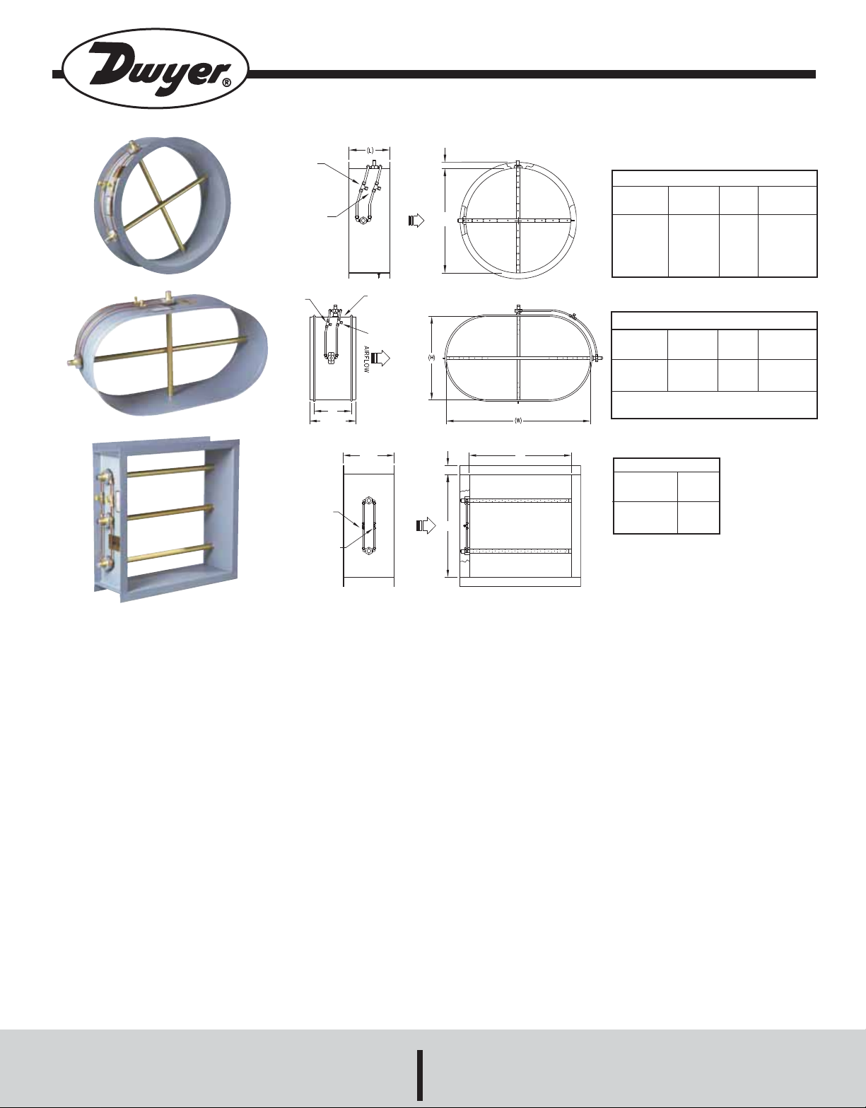
The Series FLST Airflow Measurement Station consists of single or
multiple airflow elements, factory mounted and pre-piped in a casing
designed for flanged connection to the ductwork. Standard materials consist of a G90 galvanized casing and 6063-T5 anodized aluminum flow sensors, suitable for most HVAC applications.
The airflow averaging element, utilized in the FLST, is a head type device,
which generates a differential (velocity) pressure signal similar to the orifice,
venturi, and other head producing primary elements. The FLST is constructed so that strategically located sensing ports (based on duct size)
continually sample the total and static pressures, when inserted normal to
flow. The total pressures sensed by the upstream ports are continually
averaged within the element in an isolated chamber. The static sensing
ports (located where the influence of the velocity head is zero) are averaged
in a second isolation chamber. Multiple elements are manifolded together
for connection to a differential measurement device (gage, transmitter, etc.)
for flow measurement and indication purposes.
SPECIFICATIONS
Accuracy: Within 2% of actual flow when installed in accordance with
published recommendations.
Velocity Range: 100 to 10,000 fpm (0.51 to 51 m/s).
Wetted Material: Elements 6063-T5 anodized aluminum; Casings 16 ga
G90 galvanized steel.
Temperature Limits: Galvanized Casings and Aluminum Elements
350°F (177°C) continuous operation (in air) 400°F (204°C) intermittent
operation (in air).
Humidity: All Airflow Stations 0 to 100% non condensing.
Process Connections: 1/4˝ compression fittings.
DWYER INSTRUMENTS, INC.
Phone: 219/879-8000 www.dwyer-inst.com
P.O. BOX 373 • MICHIGAN CITY, INDIANA 46361, U.S.A. Fax: 219/872-9057 e-mail: info@dwyer-inst.com
Page 2
Circular Flange Dimensions
Station
Size
6˝ - 15˝
16˝ - 44˝
45˝ - 72˝
73˝ & Over
Circular Stations
Standard circular airflow measuring stations include a 16 gage galvanized
casing with attached 90° connecting flanges as listed above.
Flange
Thickness
0.064˝
0.064˝
0.188˝
0.188˝
Flange
Size
1˝
1-1/2˝
1-1/2˝
2˝
Casing
Length “L”
6˝
6˝
10˝
12˝
Oval Flange Dimensions (Optional)
Station
Size
Up to 48˝
Over 48˝
Oval Stations
Standard oval airflow measuring stations include a 18 gage galvanized
casing, 5 inches long between beads with 1-1/4 inch connecting sleeve
on each end (7-1/2 inch overall length). Actual O.D. dimensions are 1/4
inch less than specified duct I.D. dimensions.
Flange
Thickness
0.064˝
0.188˝
Flange
Size
1-1/2˝
1-1/2˝
Casing
Length “L”
6˝
8˝
Rectangular Flange Dimensions
Station Size
8˝ - 72˝
73˝ & Over
Rectangular Stations
Standard rectangular airflow measuring stations include a 16 gage galvanized casing, 5 inches long, with formed integral 90° connecting flanges
as listed above.
Flange Size
1-1/2˝
2˝
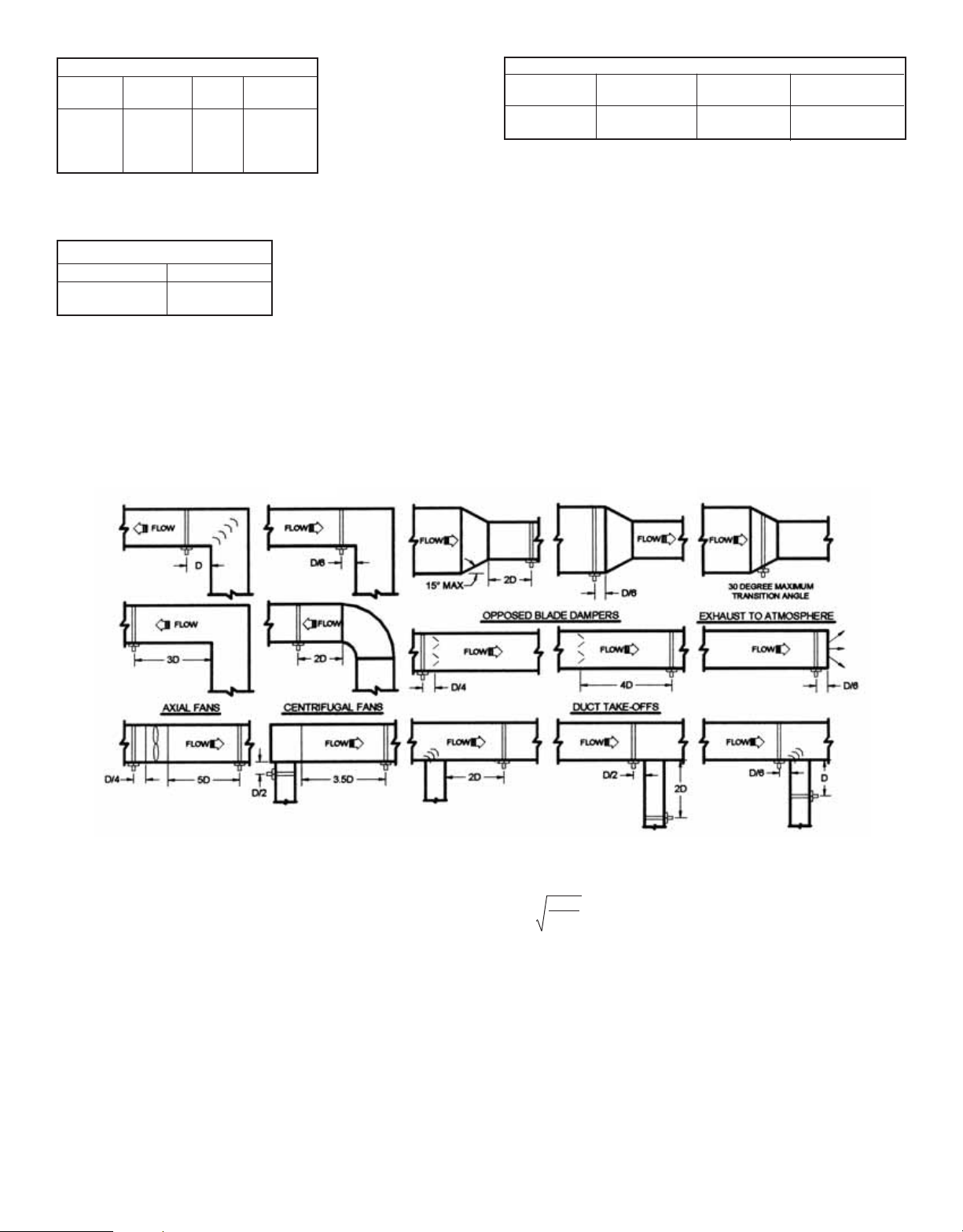
ELBOWS
INSTALLATION
The elements may be installed in any duct configuration. However, the
accuracy of the installation is dependent on the flow conditions in the
duct. The minimum installation requirements for the elements based upon
a uniform velocity profile approaching the duct disturbance for flow rates
less than 2,500 fpm are shown below. Add one duct diameter to the
installation requirements shown below for each additional flow rate of
1000 fpm. These are not ideal locations. It is always best to locate the elements as far as possible from all duct disturbances, with upstream disturbances being the most critical consideration.
TRANSITIONS
Notes:
Round Ducts:
D = Duct diameter
Rectangular Ducts:
D = 4HW
π
H = Duct height
W = Duct width
Page 3

FLST RESISTANCE to AIRFLOW
FLST SPECIFICATION GUIDE
1. Provide where indicated and/or scheduled airflow traverse elements
capable of continuously monitoring the fan or duct air volumes they serve.
2. Each element shall be designed and built to comply with, and provide
results in accordance with, accepted practice for duct system traversing as
defined in the ASHRAE Handbook of Fundamentals, AMCA publication
#203, as well as the Industrial Ventilation Handbook. The number of sensing ports on each element, and the quantity of elements utilized at each
installation, shall comply with ASHRAE Standard #111 for equal area duct
traversing.
3. Each airflow measuring element shall contain multiple total and static
pressure sensing ports placed along the leading edge of the cylinder. The
static pressure chamber shall incorporate dual offset static taps on opposing sides of the averaging chamber, so as to be insensitive to flow angle
variations of as much as ±20 degrees in the approaching airstream.
4. The airflow traverse elements shall be capable of producing steady, nonpulsating signals of true total and static pressure, with an accuracy of 2%
of actual flow for operating velocities as low as 100 feet per minute (fpm).
Signal amplifying sensors requiring flow correction (K factors) for field calibration are not acceptable.
5. The airflow traverse elements shall not induce a measurable pressure
drop, greater than 0.18 inch at 4,000 fpm. The units sound level within the
duct shall not be amplified, nor shall additional sound be generated.
6. The probes shall be manifolded together in a 16 gauge galvanized steel
duct section with 90 degree undrilled flanges, fabricated to the duct size,
and shall contain multiple airflow traverse elements interconnected as herein before described.
Installation Considerations
1. Primary flow elements shall be installed in strict accordance with the
manufactures published requirements and with ASME guidelines affecting
non-standard approach conditions. These elements serve as the primary
signals for the airflow systems; it shall be the responsibility of the contractor to verify correct installation to assure that accurate primary signals are
obtained.
2. An identification label shall be placed on each unit casing listing model
number, size, area, and specified airflow capacity.
7. Where primary flow elements are located outside of the manufacturer’s
published installation guidelines the manufacturer shall be consulted, and
approve of any special configurations, such as air equalizers and/or additional and strategically placed measuring points, as may be required.
8. Where the stations are installed in insulated ducts, the airflow passage
of the station shall be the same size as the inside airflow dimension of the
duct. Station flanges shall be sized to facilitate matching connecting ductwork.
Page 4

Engineering Reference Table
V = Velocity in feet per minute Pv = Velocity Pressure in inches H
Velocity Versus Velocity Pressure
2
O
V
180
190
200
210
220
230
240
250
260
270
280
290
300
310
320
330
340
350
360
370
380
390
400
410
420
430
440
450
460
470
480
490
500
510
520
530
540
550
560
570
580
590
600
610
Pv
0.0020
0.0023
0.0025
0.0027
0.0030
0.0033
0.0036
0.0039
0.0042
0.0045
0.0049
0.0052
0.0056
0.0060
0.0064
0.0068
0.0072
0.0076
0.0081
0.0085
0.0090
0.0095
0.0100
0.0105
0.0110
0.0115
0.0121
0.0126
0.0132
0.0138
0.0144
0.0150
0.0156
0.0162
0.0169
0.0175
0.0182
0.0189
0.0196
0.0203
0.0210
0.0217
0.0224
0.0232
Above Pv Values are Based on Standard Air Density of 0.075 lbm ft3which is Air at 68°F. 50% Relative Humidity, and 29.92˝ Hg.
V
620
630
640
650
660
670
680
690
700
710
720
730
740
750
760
770
780
790
800
810
820
830
840
850
860
870
880
890
900
910
920
930
940
950
960
970
980
990
1000
1010
1020
1030
1040
1050
Pv
0.0240
0.0247
0.0255
0.0263
0.0272
0.0280
0.0288
0.0297
0.0305
0.0314
0.0323
0.0332
0.0341
0.0351
0.0360
0.0370
0.0379
0.0389
0.0399
0.0499
0.0419
0.0429
0.0440
0.0450
0.0461
0.0472
0.0483
0.0494
0.0505
0.0516
0.0528
0.0539
0.0551
0.0563
0.0575
0.0587
0.0599
0.0611
0.0623
0.0636
0.0649
0.0661
0.0674
0.0687
The equation for converting air volume (Q) into velocity (V) and velocity pressure (Pv) is:
V
1060
1070
1080
1090
1100
1110
1120
1130
1140
1150
1160
1170
1180
1190
1200
1210
1220
1230
1240
1250
1260
1270
1280
1290
1300
1310
1320
1330
1340
1350
1360
1370
1380
1390
1400
1410
1420
1430
1440
1450
1460
1470
1480
1490
Pv
0.0701
0.0714
0.0727
0.0741
0.0754
0.0768
0.0782
0.0796
0.0810
0.0825
0.0839
0.0853
0.0868
0.0883
0.0898
0.0913
0.0928
0.0943
0.0959
0.0974
0.0990
0.1006
0.1021
0.1037
0.1054
0.1070
0.1086
0.1103
0.1119
0.1136
0.1153
0.1170
0.1187
0.1205
0.1222
0.1239
0.1257
0.1275
0.1293
0.1311
0.1329
0.1347
0.1366
0.1384
V
1500
1510
1520
1530
1540
1550
1560
1570
1580
1590
1600
1610
1620
1630
1640
1650
1660
1670
1680
1690
1700
1710
1720
1730
1740
1750
1760
1770
1780
1790
1800
1810
1820
1830
1840
1850
1860
1870
1880
1890
1900
1910
1920
1930
Pv
0.1403
0.1422
0.1440
0.1459
0.1479
0.1498
0.1517
0.1537
0.1556
0.1576
0.1596
0.1616
0.1636
0.1656
0.1677
0.1697
0.1718
0.1739
0.1760
0.1781
0.1802
0.1823
0.1844
0.1866
0.1888
0.1909
0.1931
0.1953
0.1975
0.1998
0.2020
0.2040
0.2065
0.2088
0.2111
0.2134
0.2157
0.2180
0.2203
0.2227
0.2251
0.2274
0.2298
0.2322
V
1940
1950
1960
1970
1980
1990
2000
2020
2040
2060
2080
2100
2120
2140
2160
2180
2200
2220
2240
2260
2280
2300
2320
2340
2360
2380
2400
2420
2440
2460
2480
2500
2520
2540
2560
2580
2600
2620
2640
2660
2680
2700
2720
2740
Pv
0.2346
0.2371
0.2395
0.2420
0.2444
0.2469
0.2494
0.2544
0.2595
0.2646
0.2697
0.2749
0.2802
0.2855
0.2909
0.2963
0.3017
0.3073
0.3128
0.3184
0.3241
0.3298
0.3356
0.3414
0.3472
0.3531
0.3591
0.3651
0.3712
0.3773
0.3834
0.3897
0.3959
0.4022
0.4086
0.4150
0.4214
0.4280
0.4345
0.4411
0.4478
0.4545
0.4612
0.4681
V
2760
2780
2800
2820
2840
2860
2880
2900
2920
2940
2960
2980
3000
3020
3040
3060
3080
3100
3120
3140
3160
3180
3200
3220
3240
3260
3280
3300
3320
3340
3360
3380
3400
3420
3440
3460
3480
3500
3520
3540
3560
3580
3600
3620
Pv
0.4749
0.4818
0.4888
0.4958
0.5028
0.5099
0.5171
0.5243
0.5316
0.5389
0.5462
0.5536
0.5611
0.5686
0.5762
0.5838
0.5914
0.5991
0.6069
0.6147
0.6225
0.6304
0.6384
0.6464
0.6545
0.6626
0.6707
0.6789
0.6872
0.6955
0.7038
0.7122
0.7207
0.7292
0.7378
0.7464
0.7550
0.7637
0.7725
0.7813
0.7901
0.7990
0.8080
0.8170
V
3640
3660
3680
3700
3720
3740
3760
3780
3800
3820
3840
3860
3880
3900
3920
3940
3960
3980
4000
4050
4100
4150
4200
4250
4300
4350
4400
4450
4500
4550
4600
4650
4700
4750
4800
4850
4900
4950
5000
5050
5100
5150
5200
5250
Pv
0.8260
0.8351
0.8443
0.8535
0.8627
0.8720
0.8814
0.8908
0.9002
0.9097
0.9193
0.9289
0.9386
0.9483
0.9580
0.9678
0.9777
0.9876
0.9975
1.0226
1.0480
1.0737
1.0997
1.1261
1.1527
1.1797
1.2070
1.2346
1.2625
1.2907
1.3192
1.3480
1.3772
1.4066
1.4364
1.4665
1.4969
1.5276
1.5586
1.5899
1.6216
1.6535
1.6858
1.7184
V
5300
5350
5400
5450
5500
5550
5600
5650
5700
5750
5800
5850
5900
5950
6000
6050
6100
6150
6200
6250
6300
6350
6400
6450
6500
6550
6600
6650
6700
6750
6800
6850
6900
7000
7100
7200
7300
7400
7500
7600
7700
7800
7900
8000
Pv
1.7512
1.7844
1.8180
1.8518
1.8859
1.9204
1.9551
1.9902
2.0256
2.0613
2.0973
2.1336
2.1702
2.2071
2.2444
2.2819
2.3198
2.3580
2.3965
2.4353
2.4744
2.5139
2.5536
2.5937
2.6340
2.6747
2.7157
2.7570
2.7986
2.8406
2.8828
2.9253
2.9682
3.0549
3.1428
3.2319
3.3223
3.4140
3.5069
3.6010
3.6964
3.7930
3.8909
3.9900
Where
V = Q
PV = V 2 x p
A
MAINTENANCE
Since the sensing elements have no moving parts, only periodic cleaning
may be required. The sensing elements should be inspected for fouling of
the sensing holes as part of an annual preventative maintenance program.
Installations having viscous airborne particles may require more frequent
inspection. If the sensing holes on the elements have become fouled or
plugged, the following procedure is recommended. Caution, all instru-
ments must be isolated (removed) from the sensing lines prior to
performing the following cleaning procedure.
[
[
C
V = Velocity in fpm C = 1096.7
Q = Flow in efm p = Density of air in lb/ft
A = Area in ft
2
Pv = Velocity pressure in inches H2O
3
Cleaning: In applications where the sensing elements are subject
to viscous contaminants it is recommended that the surface be
washed with a cleaning agent. The cleaning agent used must be
suitable for use on the type of material the sensing element is constructed of (i.e. aluminum, stainless steel, etc.)
The Series FLST Duct Mounted Airflow Measurement Station is
not field serviceable and should be returned if repair is needed
(field repair should not be attempted and may void warranty). Be
sure to include a brief description of the problem plus any relevant
application notes. Contact customer service to receive a return
Backpurging: Connect clean/dry compressed air, set at a maximum
pressure of 25 psi, to the output pressure ports (total and/or static) of the
sensing element being cleaned. While purging the sensing element, wipe
the surface of the cylinder with a cloth or brush to loosen and remove all
contaminate buildup.
goods authorization number before shipping.
©Copyright 2009 Dwyer Instruments, Inc. Printed in U.S.A.1/09 FR# R1-443414-00 A Rev. 1
DWYER INSTRUMENTS, INC.
Phone: 219/879-8000 www.dwyer-inst.com
P.O. BOX 373 • MICHIGAN CITY, INDIANA 46361, U.S.A. Fax: 219/872-9057 e-mail: info@dwyer-inst.com
 Loading...