

Page 1
Bulletin IN-EDAW
Series EDA Electronic Pressure Controller
Specifications - Installation and Operating Instructions
DWYER INSTRUMENTS, INC.
P.O. BOX 373 • MICHIGAN CITY, IN 46360, U.S.A. Fax: 219/872-9057 e-mail: info@dwyer-inst.com
Phone: 219/879-8000 www.dwyer-inst.com
Page 2

ONTENTS
C
Dimensions . . . . . . . . . . . . . . . . . . . . . . . . . . . . . . . . . . . . . . . . . . . . . . . . . . . . . .1
Specifications . . . . . . . . . . . . . . . . . . . . . . . . . . . . . . . . . . . . . . . . . . . . . . . . . . . .2
Model Chart . . . . . . . . . . . . . . . . . . . . . . . . . . . . . . . . . . . . . . . . . . . . . . . . . . . . .3
Display . . . . . . . . . . . . . . . . . . . . . . . . . . . . . . . . . . . . . . . . . . . . . . . . . . . . . . . . .3
nstallation Instructions . . . . . . . . . . . . . . . . . . . . . . . . . . . . . . . . . . . . . . . . . .4 – 5
I
npacking and Mounting . . . . . . . . . . . . . . . . . . . . . . . . . . . . . . . . . . . . . . . . .4
U
lectrical Connections . . . . . . . . . . . . . . . . . . . . . . . . . . . . . . . . . . . . . . . . . . .5
E
Operating Instructions . . . . . . . . . . . . . . . . . . . . . . . . . . . . . . . . . . . . . . . . . .6 - 18
Front Panel Functions . . . . . . . . . . . . . . . . . . . . . . . . . . . . . . . . . . . . . . . . . . .6
Set Points & Alarms . . . . . . . . . . . . . . . . . . . . . . . . . . . . . . . . . . . . . . . . . .7 - 8
Alternation (Lead/Lag) Operation . . . . . . . . . . . . . . . . . . . . . . . . . . . . . . . . . .8
rogramming Chart . . . . . . . . . . . . . . . . . . . . . . . . . . . . . . . . . . . . . . . . .9 - 11
P
ain Menu Selections . . . . . . . . . . . . . . . . . . . . . . . . . . . . . . . . . . . . . . . . . .12
M
enus and Values . . . . . . . . . . . . . . . . . . . . . . . . . . . . . . . . . . . . . . . . .12 - 18
M
Security Menu . . . . . . . . . . . . . . . . . . . . . . . . . . . . . . . . . . . . . . . . . . . . .12
Operation Menu . . . . . . . . . . . . . . . . . . . . . . . . . . . . . . . . . . . . . . . . . . . .13
Output Menu . . . . . . . . . . . . . . . . . . . . . . . . . . . . . . . . . . . . . . . . . .14 – 15
Display Menu . . . . . . . . . . . . . . . . . . . . . . . . . . . . . . . . . . . . . . . . . . . . . .16
Advanced Menu . . . . . . . . . . . . . . . . . . . . . . . . . . . . . . . . . . . . . . . . . . . .16
Test Menu . . . . . . . . . . . . . . . . . . . . . . . . . . . . . . . . . . . . . . . . . . . . . . . .17
Failsafe Menu . . . . . . . . . . . . . . . . . . . . . . . . . . . . . . . . . . . . . . . . . . . . .17
Diagnostic Error Messages . . . . . . . . . . . . . . . . . . . . . . . . . . . . . . . . . . . . . . . . .18
Warranty Information . . . . . . . . . . . . . . . . . . . . . . . . . . . . . . . . . . . . . . . . . . . . .18
Page 3
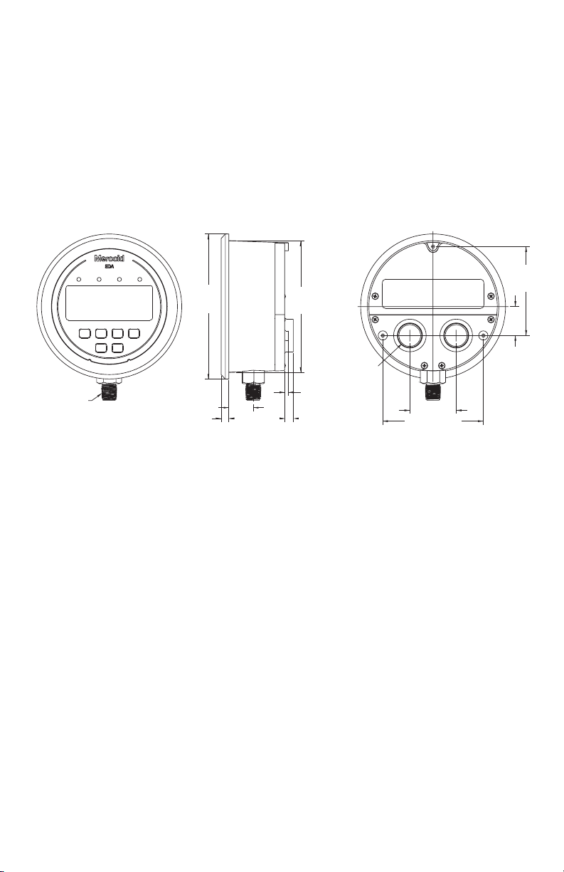
Dimensions
1/4 MALE NPT
WITH 3/4 [19.05]
WRENCHING HEX
9/32 [7.14]
Ø 5
[127.00]
Ø 4-17/32
[115.09]
1
[25.40]
3-1/16
[77.89]
27/32
[21.43]
1-59/64 [26.16]
2X 5/16 [7.93]
3-15/32 [88.11]
1-5/8 [41.28]
[40.88]
3X 1/8 [3.18]
1/2 FEMALE NPT
CONDUIT ENTRY
1
Page 4

SPECIFICATIONS
Service: Compatible liquids and gases.
Wetted Materials: 316L SS.
ousing: Glass filled plastic.
H
ccuracy: ±1% of F.S. including linearity, hysteresis, and repeatability (indicator and transmitter).
A
tability: < ± 2% of F.S. per year.
S
Pressure Limits: Ranges up to 6,000 psi: 1.5 x range; 8,000 psi range: 10,000 psi.
Temperature Limits: Ambient: 20 to 140°F (-6.6 to 60°C); Process: 0 to 176°F (-18 to 80°C).
Compensated Temperature Limits: 32 to 122°F (0 to 50°C).
Thermal Effect: ±0.05% of F.S./°F.
Process Connection: 1/4˝ NPT male, 1/4˝ BSPT male, or 7/16” SAE.
Display: 4-digit backlit LCD (Digits: 0.60˝H x 0.33” W).
Display Update: 600 ms (dampening set to 1).
ower Requirements: 12 to 28 VDC ( ) / AC ( ~ ) 50/60 Hz. (Can work at 8 VDC ( ) for 45 seconds). For T5
P
ption: 14 to 30 VDC ( ) / AC ( ~ ) 50/60 Hz.
o
ower Consumption: 2.5 watts.
P
Electrical Connections: Removable terminal blocks with two 1/2˝ female NPS conduit connections.
Enclosure Rating: Weatherproof type 4X IP65 (IP65 not evaluated by UL). Unit is rated weatherproof but if unit is
panel mounted, panel will not maintain 4X rating.
Warm Up Time: <10 seconds.
Mounting Orientation: Any position.
Weight: 1.18 lbs (535 g).
Installation Category: II (transient over-voltage).
Pollution Degree: 2.
Altitude Limit: 6560 ft (2000 m) max.
Environment: Intended for indoor and outdoor use.
Humidity: 0 to 95% RH up to 104°F (40°C) non-condensing, 10 to 50% at 140°F (60°C) non-condensing.
SWITCH SPECIFICATIONS
Switch Type: 2 SPDT relays.
Electrical Rating: 5A @ 120/240 VAC ( ~ ) 50/60 Hz, 1A @ 28 VDC ( ).
Repeatability: ±1% of FS (switching only).
Set Points: Adjustable 0-100% of FS.
Switch Indication: External LED for each relay on the front panel.
Switch Reset: Manual or automatic.
TRANSMITTER SPECIFICATIONS
Output Signal: 4 – 20 mA, 1 - 6 VDC ( ), 1 - 5 VDC ( ), 0 - 5 VDC ( ), or 0 - 10 VDC ( )(direct or
reverse output selection).
Minimum Excitation: 14 VDC ( ).
Zero and Span Adjustments: Menu scalable within the range.
2
Page 5

Model Number Chart
Example
eries
S
ousing
H
rocess
P
Connection
Electrical
Connection
ange
R
Transmitter
Output
Options
*Not UL listed.
Display
The EDA has two displays: a lower larger display and a smaller upper display. The Home Display is the normal display while the control is in operation if there are no errors or functions active. The Home display will indicate the
process variable at the current condition with the lower display and the selected pressure units for the process variable with the upper display. When programming the unit both displays are also used. The Programming Chart in this
instruction manual indicates what both displays show while programming the unit. For programming descriptions in
this instruction manual the format used is “lower display – upper display”. For example Ctrl – 1SP shows that Ctrl
would be in the lower display and 1SP would be in the upper display.
DA
E
DA
E
W
1
N
1
B
A1
E1
1
0
02
03
04
05
6
0
7
0
08
09
10
11*
12*
T0
T1
T2
T3
T4
T5
EDAW-N1E1-01T0-SST
Electronic Pressure Controller
eatherproof
W
/4˝ NPT male bottom
1
/4˝ BSPT male bottom
1
7/16˝ SAE male bottom
Two 1/2˝ female NPT
conduit connections
0 – 30” Hg vacuum
0 – 20 psi
0 – 60 psi
0 – 100 psi
– 150 psi
0
– 300 psi
0
– 600 psi
0
0 – 1000 psi
0 – 1500 psi
0 – 3000 psi
0 – 6000 psi
0 – 8000 psi
None
4 to 20 mA
1 to 5 VDC
0 to 5 VDC
1 to 6 VDC
0 to 10 VDC
STW
Stainless Steel Tag
NIST
NIST Certificate
23444
Special Cleaning
When the user presses the E key to edit an item’s value the upper display will flash “EDIT” and the lower display will
blink. When the user presses the E key to then save the edit to the value the upper display will flash “SAVE” and
the lower display will stop blinking.
3
Page 6
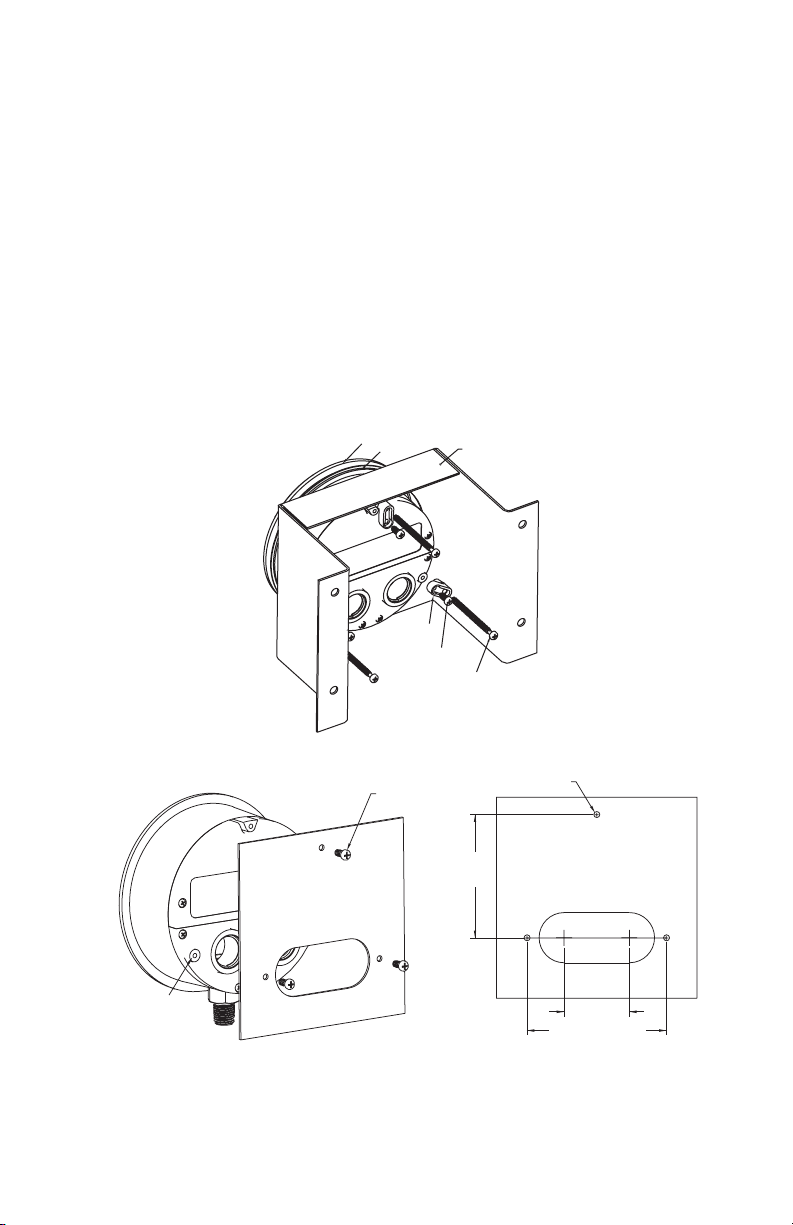
1.0 INSTALLATION
A-370 MOUNTING
BRACKET
EDAW
SEAL
3X MOUNTING
LUG
3X 4-20 X 3/8 SCREWS
3X 6-20 X 2-1/4 SCREWS
3X 4-20 X 3/8
SCREWS
3X ø 1/8 [3.18]
3-1/16
[77.89]
MOUNTING
HOLE DEPTH
3/8 [9.53]
1-5/8
[41.28]
3-15/32 [88.11]
1.1 UNPACKING
emove the EDA from the shipping carton and inspect for damage. If damage is found, notify the carrier immediate-
R
y.
l
1.2 MOUNTING
The EDA can be pipe, panel, or surface mounted. For pipe mounting thread the unit into a mating female fitting on
the pipe. Use a wrench on the 3/4˝ hex at the base of the housing to tighten the unit to the mating fitting. Do not
hread the unit in by force on the housing. For panel mounting the unit fits into a 4-13/16” (122.24 mm) panel cut out.
t
nsert the unit into the panel opening and secure in place with the machine screws and adaptors provided with the
I
nit as shown in Figure 1 below. Maximum panel thickness is 1/8” (3.5 mm) with supplied screws. For surface mount-
u
ing, panel mount the unit into the A-370 mounting bracket (See the Dwyer catalog or website for ordering details)
also shown in Figure 1. The unit can also be directly surface mounted, as shown in Figure 2, with the proper panel
cutout for the conduit entrances. Support the pressure connection hex with a wrench if attaching a fitting to the unit
in the case of panel or flush mounting so that the pressure connection does not twist. Use a small amount of
plumber’s tape or other suitable sealants to prevent leaks around fitting.
Figure 1: Panel Mounting and Mounting in A-370 Bracket
Figure 2: Surface Mounting
4
Page 7

1.3 ELECTRICAL CONNECTIONS
S
P1
RELAY
5A 250 VAC FOR LOADS USING 120/240 VAC POWER
1A 32 VDC FOR LOADS USING 30 VDC POWER
375 mA 250 VAC
LOAD 1
LOAD 2
LINE
INPUT
12 TO 30 VDC/AC
POWER
S
P2 OR ALARM
RELAY
CAUTION: POWER MUST BE OFF WHILE WIRING CONNECTIONS ARE BEING MADE.
CAUTION: Do not exceed the specified supply voltage rating. Permanent damage not covered by the warranty
ay result.
m
AUTION: To maintain type 4X rating of the enclosure, 1/2 NPT conduit fittings must have a UL type 4X out-
C
oor rating.
d
Note: Installation must be made in accordance with local codes and regulations. When fishing wire through the conduit
onnection do not allow the wire to touch or press on components on the boards. Damage to the circuitry may result.
c
Electrical connections are made to the removable terminal blocks inside the enclosure. Remove the top back cover, do
not remove bottom cover. Feed stripped and tinned leads through the conduit opening and connect them as shown in
Figure 3. The EDA provides two 1/2˝ NPT female ports for conduit connection. The conduit connections must be made
such that condensation is not allowed to enter the sensor housing. If necessary install a conduit breather drain in a sep-
rate conduit body to prevent buildup of moisture. It is recommended that shielded twisted pair wire be used for the
a
ransmitter output option if the potential exists for interference from external noise sources. When replacing top back
t
cover tighten screws to 2 ±.25 in. lbs.
Figure 3: Wiring
An external power supply of 12-28
VDC/AC with minimum current capability
of 200 mA must be used to power the unit.
The power supply connection is not polarity sensitive so the positive and negative
connections may be made to either terminal of CONN9 terminal block.
For voltage output option, connect the voltage receiver (-) to terminal 1 and voltage
receiver (+) to terminal 2 of the CONN10
terminal block. For current output option,
connect the current receiver (-) to terminal
3 and current receiver (+) to terminal 4 of
CONN10 terminal block. DO NOT APPLY
EXTERNAL POWER TO CONN10 TERMINALS - PERMANENT DAMAGE NOT
COVERED BY WARRANTY WILL
RESULT.
Loads can be connected to connectors CONN7 and CONN8 terminal blocks based on the Control settings:
• For single set point mode (CtrL-1SP), connect the Load to SP1 relay (CONN7).
• For two set points mode (CtrL-2SP), connect the Load1 to SP1 relay (CONN7) and
Load2 to SP2 relay (CONN8).
• For single set point and alarm mode (CtrL-SPAL), connect the Load1 to SP1 relay
(CONN7) and Load2 to ALARM relay (CONN8).
Wiring
An external switch or circuit breaker should be added to during the installation as a disconnecting device. The switch
or circuit breaker must meet the requirements of IEC 60947-1 and IEC 60947-3, shall disconnect all current carrying
conductors, and shall not interrupt the protective earth ground. The disconnecting switch or circuit breaker must be
marked or labeled with the symbols “I” for on and “O” for off, per IEC 60417-5007 & IEC 60417-5008 and shall be
marked as “Disconnecting Device”. Do not position the PLS in a space where it is difficult to operate the disconnecting
device that provides power. 300V @ 90°C 18 AWG/0.75 mm
2
wiring with PVC or equivalent insulation with 94-V0 or FV0 flammability rating is recommended for the switch outputs and power. Terminal blocks rated for 16-22 solid or stranded copper conductor. 6 lb in is suggested tightening torque.
WARNING
easy reach of the operator. This disconnect device must include a label indicating its function as a mains disconnect. A
As a permanently installed piece of equipment, a power disconnect switch, circuit breaker, or other
approved disconnect device must be installed in close proximity to the installed board and within
circuit breaker or fuse device is recommended (see Figure 3).
Explanation of Symbols:
Description
Direct current
Alternating current
Protective conductor terminal
On (supply)
Off (supply)
Symbol
Publication
IEC 50417 - 5031
IEC 50417 - 5032
~
IEC 50417 - 5019
IEC 50417 - 5007
IEC 50417 - 5008
5
Page 8

2. OPERATING INSTRUCTIONS
HOME POSITION FUNCTION MAIN MENU FUNCTION
ITEM FUNCTION
Enter into items
Peak/Valley resets
display to present value.
.1 FRONT PANEL & KEY FUNCTIONS
2
Figure 4: Front Panel Functions
Key Functions
6
Page 9

2.2 SET POINTS & ALARMS
The hot key provides direct access to the Set Point and Alarm settings.
The Set Point and Alarm settings that are displayed are based upon the Control (CtrL) menu item.
Setting Set Points and Alarms
Set Point Adjustment
Adjusting the set points is quick and simple. Instead of setting a set point and dead band, simply adjust SP1H,
Set Point 1 High, and SP2H, Set Point 2 High, for the desired relay turn on point, and then adjust SP1L, Set Point
1 Low, and SP2L, Set Point 2 Low, for the desired relay turn off point.
In the above graph, an instrument with a 100 psi range would have the SP1 relay turn ON at 80 psi and OFF at 40
psi. SP1H sets the relay turn ON point, and SP1L sets the relay turn OFF point.
7
Page 10

Relay Action
The relays outputs normally function in the direct acting mode, which means the relays turn ON with an increase in
pressure. SP1 and SP2 may be configured to act as reverse acting relays (refer to the CtrL menu item). When set
for reverse acting, SP1H and SP2H set the relay turn OFF point, and SP1L and SP2L set the relay turn ON point.
The above graph demonstrates direct and reverse action on process (pressure) change.
Alternating (Lead/Lag) Operation
The EDA is designed to easily operate a pair of pumps in an alternating operation to minimize pump wear. The unit
has programmable on and off set points for pump one and two. If the lead/lag feature is turned off then the relays
remain attached to their corresponding set points, SP1H and SP1L control relay 1 (pump 1) and SP2H and SP2L
control relay 2 (pump 2). There is no alternating function.
If lead/lag feature is turned on then the relays will alternate with set points SP1H and SP1L to SP2H and SP2L with
every cycle of set points. The Last relay turned off will be last relay turned on with the next cycle. On the first cycle
on increase of pressure, assuming direct acting, the SP1 relay (pump 1) will come on and then on further increase
of pressure the SP2 relay (pump 2) will come on. On the subsequent decrease of pressure the SP2 relay (pump 2)
will come off and then the SP1 relay (pump 1) will come off. When pressure increases on the next cycle the relay
used on the last cycle for SP2 will now be used for SP1, so that SP1 now controls pump 2 and SP2 now controls
pump 1. Even if SP2 is not used on the pressure cycle the relays still alternate on next cycle.
8
Page 11

.3 PROGRAMMING CHART
HOME
MAIN MENUS
ITEMS SETTINGS
2
MENU MAP
9
Page 12

HOME
M
AIN MENUS ITEMS SETTINGS
CONTROL MODE
SELECTION
ITEMS PRESENT
WHEN “CtrL” SET
TO “1SP”, “2SP”
OR “SPAL”
ITEMS PRESENT
W
HEN “CtrL” SET
T
O “2SP”
ITEMS PRESENT
WHEN “CtrL” SET
TO “SPAL”
10
Page 13

HOME
SEE PAGE 17.
MAIN MENUS ITEMS SETTINGS
11
Page 14

2.4 MAIN MENU SELECTIONS
enu Selections
M
ress the MENU button to start the menu so that the upper right displays reads MENU. Press the ▼ key to advance
P
to the next menu item. You can press the ▲ key to go back to the previous menu. Press the E key to enter a menu.
SECr Security Menu
O
Out Output Menu
iS Display Menu
d
AdU Advanced Functions Menu
tESt Test Menu
FAIL Failsafe Menu
Menus and Values
SECr Security Menu
SECr When the security item is selected, the present security level is displayed in the upper right hand
Lock out access to set point and alarm settings, or lock out access to all settings.
PEr Operation Menu
elect pressure units, zero the display, and turn the backlight on or off.
S
Select relay mode of operation, alternating function, time delay, and lamp indication.
Monitor and adjust display related settings: Peak, Valley and Dampening.
Modify advanced function parameters: transmitter output scaling, direct or reverse output
setting, calibration, or restoring factory default calibration.
Simulate input over the range without pressure to test switch and transmitter output
function.
Set the relay and transmitter outputs to certain preset values when failsafe conditions occur.
Error codes will show on the display indicating the problem. User chooses if relay is deenergized, energized, or no action taken. With transmitter option, user chooses an output
of 3.6 mA, 22 mA, or no action taken.
display. To change the security level, adjust the number displayed to the password value in the
Password Table, shown below, by pressing the ▲ or ▼ key and then pressing the E key at the desired
security level.
Security Level
Displayed
1
2
3
4
The password values shown in the table cannot be altered, so retain a copy of these pages for future reference.
Access
All menus access
Menu Access
SP/AL Locked
SP/AL Access
Menus Locked
All settings locked
Password
Value to Enter
10
70
90
111
12
Page 15

OPEr Operation Menu
nit Pressure Units
U
Pressure Range vs. Available Units
PSI
-14.70
20.00
60.0
100.0
150.0
300.0
600
1000
1500
3000
6000
8000
ith the display reading Unit - PSI, press the E key. The upper display will blink. Press the ▼ key to
W
hange unit then press E key to save the new unit.
c
PSI Pounds per square inch
FS % of full scale
OZIN Ounces per square inch
MWC Centimeters of water column
C
PA Megapascals
M
AR Bar
B
MBAR Millibar
KPA Kilopascals
FTWC Feet of water column
KGCM Kilograms per square centimeter
MMHG Millimeters of mercury
INWC Inches of water column
INHG Inches of mercury
INHg
KG/CM2
-1.033
1.406
4.22
7.03
10.55
21.09
42.2
70.3
105.5
210.9
422
562
BAR
-1.013
1.379
4.14
6.89
10.34
20.68
41.4
68.9
103.4
206.8
414
551
-29.93
40.7
122.2
203.6
305.4
611
1222
2036
3054
FTWC
-33.94
46.1
138.4
230.7
346.0
692
1384
2307
3460
KPA
-101.4
137.9
414
689
1034
2068
MPA
-0.101
0.1379
0.414
0.689
1.034
2.068
4.14
6.89
10.34
20.68
41.4
55.1
INWC
-407.3
554
1663
2771
MBAR
-1013
1379
CMWC
-1034
1406
MMHg
-761
1035
3105
OZ/IN2
-235.2
320.0
960
1600
2400
% FS
100
100
100
100
100
100
100
100
100
100
100
100
ZERO Auto Zero
Note: DO NOT apply any pressure when performing this function. With the display
reading xx - ZERO, press the E key. The upper display will blink. Press E again to zero the display.
The display will read 0.0 if the zero offset is less than ±5% of full scale.
bCLt Backlight
ON Backlight always on.
OFF Backlight always off.
30 Backlight stays on for 30 minutes.
10 Backlight stays on for 10 minutes.
5 Backlight stays on for 5 minutes.
2 Backlight stays on for 2 minutes.
13
Page 16

Ut Output Menu
O
trL Control Mode
C
SP SP1, Set Point 1, Reverse or Direct Acting
1
1SP Single set point.
2SP Two fully independent set points.
SPAL Single set point and alarm.
IR Direct. Relay turns on with increasing pressure.
D
EV Reverse. Relay turns on with decreasing pressure.
R
DEL1 SP1, Set Point 1, Time Delay
Ed1 SP1, Set Point 1, Lamp
L
The following SP2 function values are only activated when CtrL is set to 2SP:
2SP SP2, Set Point 2, Reverse or Direct Acting
DEL2 SP2, Set Point 2, time delay
LEd2 SP2, Set Point 2, Lamp
LdL9 Relay Alternation (See page 8)
Sets the amount of time a set point condition must be continuously met before the set point condition
is recognized. The DEL1 delay is adjustable from 0-60 seconds.
OFF The SP1 LED on the front panel turns OFF when the SP1 relay turns OFF.
The SP1 LED on the front panel turns ON when the SP1 relay turns ON.
ON The SP1 LED on the front panel turns ON when the SP1 relay turns OFF.
The SP1 LED on the front panel turns OFF when the SP1 relay turns ON.
DIR Direct. Relay turns on with increasing pressure.
REV Reverse. Relay turns on with decreasing pressure.
Sets the amount of time a set point condition must be continuously met before the set point
condition is recognized. The DEL2 delay is adjustable from 0-60 seconds.
OFF The SP2 LED on the front panel turns OFF when the SP2 relay turns OFF.
The SP2 LED on the front panel turns ON when the SP2 relay turns ON.
ON The SP2 LED on the front panel turns ON when the SP2 relay turns OFF.
The SP2 LED on the front panel turns OFF when the SP2 relay turns ON.
OFF There is no alternating function.
ON Relays will alternate with set points SP1H/L and SP2H/L with every cycle of set
points. 2SP control mode only.
14
Page 17

The following alarm function menu items are activated when CtrL is set to SPAL:
ELA Alarm Delay
D
ets the amount of time an alarm condition must be continuously met before the alarm condition is
S
recognized. The alarm delay is adjustable from 0 - 60 seconds.
LEdA Alarm Lamps
AL Alarm Type (see Alarm Adjustment below)
Alarm Adjustment
Alarm settings are dependent upon the selected alarm type. The EDA pressure controller alarm may be configured
as a High Alarm, Low Alarm, or High/Low Alarm. Alarm settings may be set to anywhere within the range of the
instrument. The dead bands of the alarms are fixed at 1% of full scale.
OFF The ALLO LED or ALHI LED on the front panel turns OFF when the alarm relay
N The ALLO LED or ALHI LED on the front panel turns ON when the alarm relay
O
IGH High alarm only.
H
LOW Low alarm only.
HILO For a high and low guard band type alarm. Share the same relay output.
urns OFF. The ALLO LED or ALHI LED on the front panel turns ON when the
t
larm relay turns ON.
a
turns OFF. The ALLO LED or ALHI LED on the front panel turns OFF when the
alarm relay turns ON.
ALrE Alarm Reset
AUTO Automatic reset.
HOLD Manual reset. An alarm is reset by pressing the RST key on the front panel.
ALiH Low Alarm Inhibit
OFF Alarm inhibit is off.
ON Alarm inhibit is on.
Note: If ALiH is selected ON, a low alarm condition is suspended upon power up until the process value passes
through the alarm set point once.
15
Page 18

iS Display Menu
d
PEAK Peak
ALY Valley
V
AMP Dampening
D
AdU Advanced Menu
POL, Process Output Low, and POH, Process Output High are used to scale the transmitter output for a unit with
the output option of 4 to 20 mA, 0-5 VDC, 0-10 VDC, 1-5 VDC, or 1-6 VDC. Below shows with 4 to 20 mA output
option.
POL Process Output Low
POH Process Output High
CAL – ZERO Zero Calibration
The Peak feature stores the highest pressure reading the instrument has measured since
the last reset or power up. At power up PEAK is reset to the present pressure reading. To manually
eset the PEAK value, press the RST (RESET) key while in PEAK.
r
The Valley feature stores the lowest pressure reading the instrument has measured since
the last reset or power up. At power up VALY is reset to the present pressure reading. To manually
reset the VALY value, press the RST (RESET) key while in VALY.
djust from 1-15. Dampening stabilizes the display from instabilities due to things such as vibration
A
nd excessive pressure fluctuations. The dampening setting adjusts the amount of readings that are
a
averaged for each display update. Adjust the dampening value until the display reads a stable value for
the application.
Set to the desired display reading for the 4 mA output. May be set from 2% below
minimum scale up to POH.
Set to the desired display reading for the 20 mA output. May be set from POL to 2% above maximum
scale.
DO NOT apply any pressure when performing this function. With the display
reading CAL - ZERO, press the E key. The upper display will blink. Press the E
key again to complete the zeroing of the instrument or press the MENU key to cancel.
CAL – FS Full-scale Calibration
trAn sets the transmitter output option function for a unit with the output option of 4 to 20 mA, 0-5 VDC, 0-10 VDC,
1-5 VDC, or 1-6 VDC. Below shows with 4 to 20 mA output option.
trAn
DIR Direct Output. 4 mA output at zero, 20 mA output at full scale pressure.
REV Reverse Output. 20 mA output at zero, 4 mA output at full scale pressure.
CAL - DFLT Factory Default Calibration
With the display reading CAL - FS, apply full-scale pressure to the unit, press the E key.
The upper display will blink. Press the E key again to complete the
calibration or press the MENU key to cancel.
With the display reading CAL - DFLT, press the E key. The upper display will blink.
Press E again to restore the original factory calibration values or press the MENU key
to cancel.
16
Page 19

tESt Test Menu
ESt When selected the unit simulates a pressure input over the range to test the programming and output
t
FAIL Failsafe Menu
he Failsafe menu is used to set the relay and transmitter outputs to certain preset values when failsafe conditions
T
ccur. Error codes will show on the display indicating the problem. See Diagnostic Error Messages on the next page.
o
unction. To start an automatic simulated cycling through the pressure range press the E key. This test
f
will run continually until the E key is pressed again. To manually adjust the simulated pressure
press the ▲ or ▼ key to adjust the pressure value. To exit tESt press the MENU key.
rEL Relay Output Failsafe Condition
OUtP sets the transmitter output option failsafe condition for a unit with the output option of 4 to 20 mA, 0-5 VDC,
0-10 VDC, 1-5 VDC, or 1-6 VDC. See below chart of transmitter output action according to output signal type.
OUtP Transmitter Output Failsafe Condition
FrEs Failsafe reset
OPEN The relay is de-energized upon failsafe condition. The NO contacts will be
LSE The relay is energized upon failsafe condition. The NO contacts will be closed,
C
NORM No change applied to the relay upon failsafe condition.
LOW Transmitter output goes to low failsafe condition.
HIGH Transmitter output goes to high failsafe condition.
NORM No change applied to transmitter output upon failsafe condition.
AUTO Automatic reset - Failsafe is reset automatically when the failsafe error condition
HOLD Manual reset - Failsafe is reset when the MENU key is pressed.
opened, and the NC contacts will be closed.
and the NC contacts will be opened.
Output signal
LOW
HIGH
is removed.
4-20 mA
3.6 mA
22 mA
0-5 VDC
-0.125 VDC
5.625 VDC
0-10 VDC
-0.250 VDC
11.250 VDC
1–6 VDC
0.875 VDC
6.625 VDC
1-5 VDC
0.9 VDC
5.5 VDC
17
Page 20

4. DIAGNOSTIC ERROR MESSAGES
Meaning
isplay
D
Err1
Err2
rr3
E
rr4
E
Err5
5. MAINTENANCE/REPAIR
Upon final installation of the Series EDA, inspect and clean with water or damp cloth at regular intervals. The Series
EDA is not field serviceable and should be returned if repair is needed (field repair should not be attempted and may
void warranty.
6. WARRANTY/RETURN
Refer to “Terms and Conditions of Sales” in our catalog and on our website. Contact customer service to receive a
Return Goods Authorization number before shipping the product back for repair. Be sure to include a brief description of the problem plus any additional application notes.
ow temperature limit
L
temperature below 0°F has been applied to the sensor
A
igh temperature limit
H
A temperature above 180°F has been applied to the sensor
Sensor failure
The micro-controller is receiving invalid signal from the sensor
Over pressure limit
roof pressure have been exceeded
P
eypad short
K
©Copyright 2013 Dwyer Instruments, Inc.
DWYER INSTRUMENTS, INC.
Printed in U.S.A. 6/13
Phone: 219/879-8000 www.dwyer-inst.com
FR# 76-443725-00 Rev.4
P.O. BOX 373 • MICHIGAN CITY, IN 46360, U.S.A. Fax: 219/872-9057 e-mail: info@dwyer-inst.com
 Loading...