

Page 1
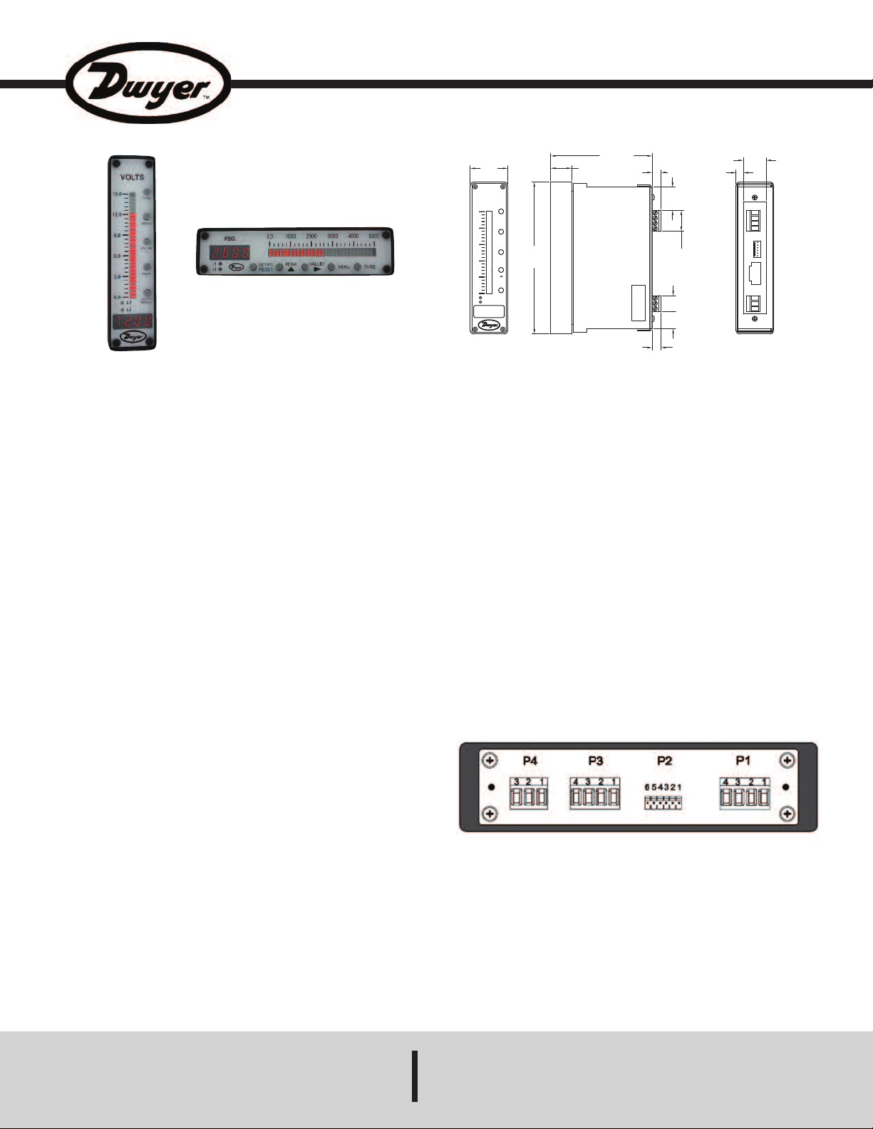
Series BGM Bar Graph Meter
X
XXX
TARE
M
ENU
V
ALLEY
>
P
EAK
S
ETPT/
RESET
X
X.X
X
X.X
XX.X
XX.X
XX.X
XX.X
L
1
L2
1-13/32
[35.56]
5-45/64
[144.78]
VERTICAL
2
1/64
[
8.33]
2
1/32
[
16.51]
19/32
[14.99]
5
1/64
[
20.07]
55/64
[21.84]
1
7/64
[
6.92]
21/64
[8.33]
3-51/64
[96.39]
25/32
[19.81]
5
5/64
[
21.72]
Installation and Operating Instructions
orizontal
H
Vertical
The Series BGM Digital Bar Graph Meter is extremely durable and can
replace a wide range of analog meters. The 4-digit display will
significantly reduce the potential for human error in reading by eliminating
errors commonly produced by the viewing angle when reading analog
meters. This series has a key pad that allows for easy access of features
without complex menu structures. With the combined ability to create a
wide range of custom faceplate and the optional NEMA 4X bezel, the
Series BGM can be used in a variety of applications. The LED bar graph
adds a visual indicator of the measured value so that it can be visually
analyzed, preventing accidents or system failures from happening.
POWER SUPPLY SPECIFICATIONS
120 VAC UNITS
Input Voltage Range: 85 to 140 VAC
Input Frequency Range: 47 to 63 Hz
Power Dissipation: < 3 VA
P4 WIRING
P4 - 1 : Neutral Line
P4 - 2 : 120 VAC Hot Line
P4 - 3 : Chassies Ground - Read Cautions
5 TO 12 VDC UNITS
Input Voltage Range: 5 TO 12 VDC
Permissable Ripple: 200 mV Max
Input Current: < 200 mA
Bulletin PC-BGM
PECIFICATIONS
S
Inputs: 0 to ±10 VDC or 4 to 20 mA.
ccuracy: ±0.05% FS.
A
ower Requirements: 120 VAC 50/60 Hz, 5 to 12 VDC, or 10 to 30 VDC model
P
ependent.
d
Power Consumption:
120 VAC: 2.4 W @ 20 mA max;
5 to 12 VDC: 1.2 W @ 100 mA max;
10 to 30 VDC: 1.5 W @ 50 mA max.
Display:
LED Display: 4 red colored digits, 0.3˝ height;
LED Graph: 31 element bar, 0.2˝ W x 3.1˝ L (5.08 mm W x 78.74 mm L).
Decimal Point: 3 positions, user selectable.
Temperature Limits:
Operating: -13 to 176°F (-25 to 80°C);
Storage: -67 to 176°F (-55 to 80°C).
Enclosure Rating: NEMA 1 or NEMA 4X
Electrical Connections: Removable screw terminal blocks.
Outputs: 2 SPST relay outputs (optional).
Switch Rating: 1 A @ 200 V.
Enclosure Material:
Bezel: Black epoxy enameled steel;
Window: Acrylic;
Case and Mounting Bracket: 304 SS.
Time Delay: 0.5 sec.
Weight: 40 oz (1.13 kg).
Wiring Guide
†
, model dependent IP65 front.
P4 WIRING
P4 - 1 : GROUND
P4 - 2 : + DC
P4 - 3 : Chassies Ground - Read Cautions
10 TO 30 VDC UNITS
Rear View
Input Voltage Range: 10 TO 30 VDC
Permissable Ripple: 500 mV Max
Input Current: < 150 mA
P4 WIRING
P4 - 1 : GROUND
P4 - 2 : + DC
P4 - 3 : Chassies Ground - Read Cautions
DWYER INSTRUMENTS, INC.
P.O. BOX 373 • MICHIGAN CITY, INDIANA 46360, U.S.A. Fax: 219/872-9057 e-mail: info@dwyer-inst.com
Phone: 219/879-8000 www.dwyer-inst.com
Page 2
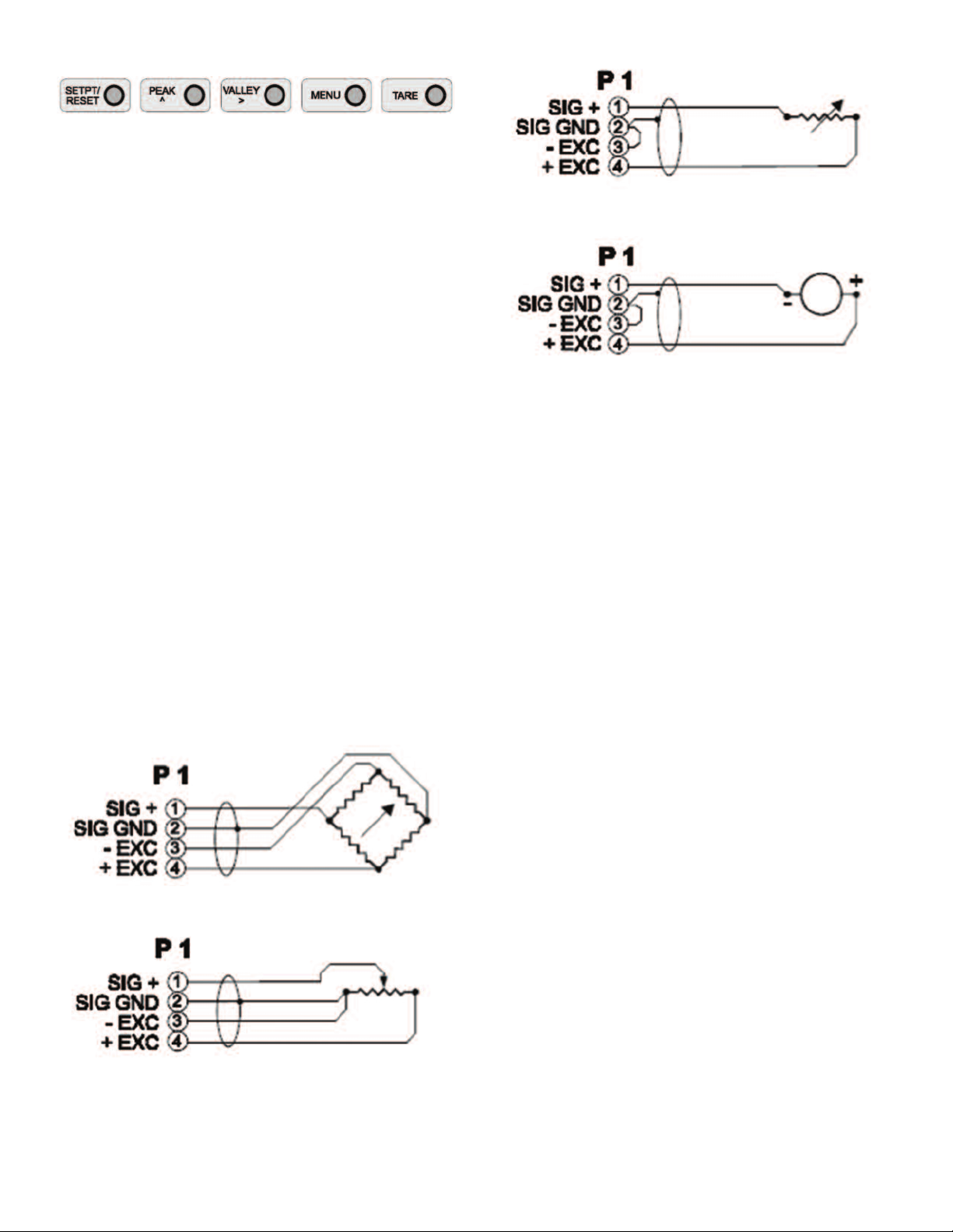
FRONT PANEL CONTROLS
PEAK / ^ (SET)
• Press and hold to view peak value
• To reset the peak value - while holding ‘PEAK’, press ‘SETPT/RESET’
momentarily.
• When in the setpoint or menu mode, this button changes the setting for
a parameter or increments the flashing digit.
SETPT / RESET
• Press momentarily to view/set setpoint 1 - see instructions below to set
a setpoint or scaling value.
• Press again momentarily to view/set setpoint 2 - see instructions below
to set a setpoint or scaling value.
• Press again momentarily to return to the operate mode.
• Press while holding ‘PEAK’, ‘VALLEY’ or ‘TARE’ to reset those values.
TARE
• Press momentarily to zero meter display.
• Display offset (TARE) value is stored until power is removed, menu is
entered or TARE is reset.
• To reset the TARE value - while holding ‘TARE’, press ‘SETPT/RESET’
momentarily.
MENU
• Press to enter the menu/scaling mode.
• Press again to exit the menu/scaling mode.
VALLEY / > (STEP)
• Press and hold to view valley value.
• To reset the valley value - while holding ‘VALLEY’, press
‘SETPT/RESET’ momentarily.
• When in the setpoint or menu mode, this button advances to the next
parameter or to the next digit.
TRANSCONDUCTANCE SENSORS
ie: PH PROBE CURRENT INPUT METERS
2 WIRE LOOP POWERED PROBES
ie: 4-20 mA TEMPERATURE TRANSMITTER
CURRENT INPUT METERS
P2 - REMOTE CONTROL INPUTS
P2 - 1: GROUND RETURN
P2 - 2: TARE
P2 - 3: SETPT / RESET
P2 - 4: PEAK / ^ (SET)
P2 - 5: VALLEY / > (STEP)
P2 - 6: MENU
Above inputs are all active low - short input to ground return or pull to
logic low to activate function; see front panel control section for a
description of each function.
CONNECTOR / PIN DESCRIPTIONS
P1 - SIGNAL INPUT
P1 - 1: SIGNAL INPUT
P1 - 2: SIGNAL RETURN
P1 - 3:+VOLTAGE RETRANSMISSION (OPTIONAL)
P1 - 4: -VOLTAGE RETRANSMISSION (OPTIONAL)
4 WIRE TRANSDUCERS
ie: LOAD CELL VOLTAGE INPUT METERS
3 WIRE TRANSDUCERS
ie: LINEAR POT VOLTAGE INPUT METERS
Installation of a shorting jumper between pins P2-5 and P2-6 disables
the five front panel push buttons.
P3 - SETPOINT RELAY OUTPUT
Note: This terminal block position will only be present if the meter is
equipped with the corresponding option.
Note: Setpoint relays are rated at 200 VAC/DC @ 1 AMP maximum.
P3 - 1: SETPOINT 1 RELAY
P3 - 2: SETPOINT 1 RELAY
P3 - 3: SETPOINT 2 RELAY
P3 - 4: SETPOINT 2 RELAY
P4 - POWER INPUT
See power supply specifications (page 1) for connection information.
Page 3

Horizontal Version Mounting
Vertical Version Mounting
Page 4

Set-Up Menu
Parameter
Decimal Point
Averaging
Setpoint 1 Active Level
Setpoint 1 Bar Indication
Setpoint 2 Active Level
Setpoint 2 Bar Indication
Bar Direction
Bar Format
Bar Starting Point Scaling
Bar Full Scale Point
CAL Point 1
CAL Point 2
Setting
d_ _0
d_0.0
d0.00
d.000
Av.16
Av.8
Av.4
Av.2
Av.1
S1.no
S1.nc
S1nF
S1Fb
S2.no
S2.nc
S2nF
S2Fb
br.bu
br.td
br.C0
bF.F
bF.d
[ ] [ ] [ ] [ ]
[ ] [ ] [ ] [ ]
CAL1
1234
CAL2
1234
Description
No Decimal Point
O.O
O.OO
O.OOO
4096 Conversions Averaged; 1 Update/Second
2048 Conversions Averaged; 2 Updates/Second
1024 Conversions Averaged; 4 Updates/Second
512 Conversions Averaged; 8 Updates/Second
256 Conversions Averaged; 16 Updates/Second
Setpoint 1 Output will be Normally Open
Setpoint 1 Output will be Normally Closed
Do Not Flash Bar
Flash Bar When Limit 1 Closes
Setpoint 2 Output will be Normally Open
Setpoint 2 Output will be Normally Closed
Do Not Flash Bar
Flash Bar When Limit 2 Closes
Bottom Up
Top Down
Center Zero or Center Reference
Full Bar Display
Moving Dot Display
Enter the Display Value for the Starting Bar LED
Enter the Display Value for the Full Scale Bar LED
Announces CAL 1 Step
Adjust Display to Desired Value for CAL 1 Input
Announces CAL 1 Step
Adjust Display to Desired Value for CAL 2 Input
To Set a Setpoint or Scaling Value
• Press and release the 'peak / ^' button until the flashing digit reaches
the desired value.
• Press the 'valley / >' button to advance to the next digit.
• Repeat until all digits are set.
Note: This meter is equipped with leading zero suppression - blank digits
are assumed to be 0's (they will not flash).
Note: To allow the entry of negative values, the msd (left most digit) will
increment 0 thru 9, -1, -(0).
Calibration Instructions
• The BGM series requires 2 known input signals for calibration / scaling.
These inputs can be of any polarity with respect to each other and should
be as far apart as possible in magnitude.
• Apply the first known input signal to the meter input.
• Simulttaneously press the 'setpt / reset' and 'tare' push buttons to
advance to the CAL 1 value setting step. Adjust the CAL 1 value on the
display until it is at the desired value for the known input. See the
instructions above to set a setpoint or scaling value.
• Simultaneously press both the 'setpt / reset' and 'tare' buttons to enter
this scaling / calibration point. Press the 'valley / >' button to advance to
the CAL 2 value setting step.
• Apply the second known input signal to the meter input.
• Adjust the CAL 2 value on the display until it is at the desired value for
the known input. See the instructions above to set a setpoint or scaling
value.
• Simultaneously press both the 'setpt / reset' and 'tare' buttons to enter
this scaling / calibration point.
CAUTION
your model number to be sure which. Line voltages always present a hazardous
and potentially lethal situation and care should be taken to ensure that power has
been removed from the circuits being wired into.
WIRING - When using stranded wire, inspect the junctions to ensure that all of the
strands are fully inserted into the terminal block, and that the terminal screw has
been tightened, before applying power to the meter.
CHASSIS GROUNDING - If local electrical codes require the case of this unit to be
electrically grounded, make the connection to P4 pin 3. If unsure of code
requirement, make the ground connection. Poor line conditions may cause this
connection to increase noise sensitivity of the meter.
;
POWER WIRING - This meter is designed to be powered from
standard linevoltages, 120 VAC or 240 VAC, not both, check
MAINTENANCE/REPAIR
Upon final installation of the Series BGM, no routine maintenance is
required. The Series BGM is not field serviceable and should be returned
if repair is needed. Field repair should not be attempted and may void
warranty.
WARRANTY/RETURN
Refer to “Terms and Conditions of Sales” in our catalog and on our
website. Contact customer service to receive a Return Goods
Authorization number before shipping the product back for repair. Be
sure to include a brief description of the problem plus any additional
application notes.
©Copyright 2013 Dwyer Instruments, Inc. Printed in U.S.A. 12/13 FR# R2-444135-00
DWYER INSTRUMENTS, INC.
Phone: 219/879-8000 www.dwyer-inst.com
P.O. BOX 373 • MICHIGAN CITY, INDIANA 46360, U.S.A. Fax: 219/872-9057 e-mail: info@dwyer-inst.com
 Loading...