

Page 1
Bulletin TE-AP2
1 IN
- -
2
- -
3
-- -
4
-
5
- --
6
- -
7
-
8
5
/16
[
7.94]
15-3/8
[390.68]
6-3/64
[153.63]
1-41/64
[41.62]
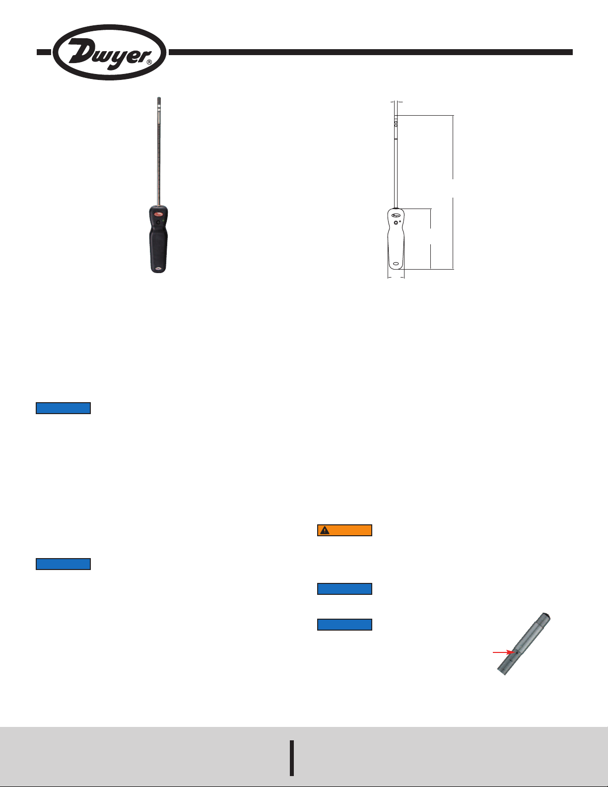
Model AP2 Wireless Thermo-Anemometer Probe for UHH
Specifications - Installation and Operating Instructions
The Model AP2 Wireless Thermo-Anemometer Probe measures air velocity, air
low, and temperature when combined with the Model UHH Universal Handheld. In
f
rder to prevent damage to the sensing element, the probe has a protective sleeve
o
hat slides over the sensor when it is not in use. Markings on the probe allow users
t
to know the insertion depth to obtain better accuracy when traversing the duct.
Wireless probes can take measurements up to 50 feet away from the UHH. A bicolor LED flashes on the handle of the probe to indicate communication status with
the UHH. The battery is rechargeable via the mini-USB connector on the bottom of
the probe.
NOTICE
This device complies with Industry Canada license-exempt RSS
standard(s). Operation is subject to the following two conditions:
(1) This device may not cause harmful interference. and (2) this device must accept
any interference received, including interference that may cause undesired
operation.
Cet appareil est conforme à des règlements d'Industrie Canada exempts de licence
standard RSS (s). Son fonctionnement est soumis aux deux conditions suivantes:
(1) Ce dispositif ne doit pas causer d'interférences nuisibles, et (2) cet appareil doit
accepter toute interférence reçue, y compris les interférences pouvant entraîner un
fonctionnement indésirable.
This Class B digital apparatus complies with Canadian ICES-003.
Cet appareil numériqué de la classe B est conformé à la norme NMB-003 du
Canada.
CHARGING BATTERY
NOTICE
It is required prior to the initial usage to charge the battery for
12 hours.
When the charge of the battery is almost used up, the LED on the handle of the
wireless probe will turn solid red. There is approximately 5 minutes of battery life
left at this point. If the probe is not already paired to the UHH, it will not pair while
in low battery condition.
Step 1: Open the USB cover on the bottom of the probe handle.
Step 2: Plug the mini-USB connector end of the cable into the probe handle.
Step 3: Plug the USB connector end of the cable into the port on the charger or
PC.
Step 4: Plug the charger into either an electrical outlet or car charging port (LED
on the charger and the handle should both light up).
Step 5: The LED on the handle will turn off when fully charged.
Step 6: Remove charger from electrical outlet.
Step 7: Remove USB connectors from the handle and the charger.
Step 8: Replace the USB cover on the bottom of the probe handle.
SPECIFICATIONS
ervice: Dry, clean air.
S
emperature Limits:
T
rocess: -20 to 200°F (-29 to 93°C);
P
Ambient: -20 to 140°F (-29 to 60°C);
Battery Charging: 32 to 113°F (0 to 45°C).
Range:
Air Velocity: 0 to 6000 FPM (0 to 30 m/s);
Volumetric Air: 999,999 in selected flow units;
Temperature: -40 to 212°F (-40 to 100°C).
Accuracy:
Air Velocity: ±3% FS within temperature range of 40 to 90°F (4 to 32°C);
Temperature: ±0.5°F (±0.28°C).
Response Time: 1 s.
Probe Length: 8˝ (203 mm) insertion.
Power Requirements: 3.7 V YT562447 Lithium ion battery, installed functional,
user replaceable.
Maximum Wireless Distance: 50´ (15 m).
Handle Enclosure: Thermoplastic elastomer over polycarbonate.
Supplied With: Wrist strap.
Weight: 11.2 oz (331.22 g).
Agency Approvals: CE (not while charging), RoHS, FCC compliant.
WARNING
Lithium ion polymer batteries are very volatile and can cause a
fire if punctured or severely damaged. Only use a Dwyer
Instruments, Inc. approved charging device in a well ventilated area away from any
flammable materials or gases. Do not incinerate the battery. Only charge between
32 to 113°F (0 to 45°C).
NOTICE
If desired, can be operated with USB cables less than 3 m in
length when connected to the charger or PC.
NOTICE
The side of the probe with the dot should
face the flow.
DWYER INSTRUMENTS, INC.
Phone: 219/879-8000 www.dwyer-inst.com
P.O. BOX 373 • MICHIGAN CITY, INDIANA 46360, U.S.A. Fax: 219/872-9057 e-mail: info@dwyermail.com
Page 2

AIRING WIRELESS PROBES
P
. Turn on Model UHH Universal Handheld by pressing the button.
1
. Press the and buttons to scroll through the menu headings at the top of the
2
display.
3. When PROBE is highlighted, hit the button to access the probe menu.
4. Press the directional arrow to scroll through the sub-menu headings. The current
elected parameter will be highlighted in yellow.
s
. When PAIRING MODE is highlighted, hit the button to access the pairing mode.
5
. Turn on the wireless probe(s) to be paired. After a period of up to 15 to 20 seconds,
6
he UHH screen will update with the information about the wireless probe(s) just
t
turned on.
NOTICE
. Press the button to scroll through the available probes. The current selected
7
robe will be highlighted in yellow.
p
. When the desired probe to be paired is highlighted, hit the button to pair the
8
probe. Once it is paired, it will be removed from the list automatically.
9. Once all the desired probes are paired, press button.
10. Repeat step 9 to go back to the home screen and begin readings.
ELECTING A PROBE
S
n order to cycle through the probes that are paired to the Model UHH Universal
I
Handheld, press the or button while in the view data mode.
SETTINGS
When using the Model AP2 Wireless Thermo-Anemometer Probe, the base unit can
isplay velocity or air flow along with temperature. The settings allow users to select
d
elocity or air flow, engineering units, measurement range, and which parameters to
v
how on the display. To access the settings menus:
s
1. Press the or directional arrows to scroll through the menu headings at the
top of the display.
2. When PROBE is highlighted, hit the button to access the probe menu.
3. Press the directional arrow to scroll through the sub-menu headings. The
currently selected parameter will be highlighted in yellow.
f a probe does not appear, power the probe down, then power
I
it back on.
ange Adjustment
R
. When sub-menu TYPE (next to Anemometer) is highlighted, hit the button to
1
ccess the settings sub-menu.
a
2. Press the directional arrow to scroll through the parameter headings. The
currently selected parameter will be highlighted in yellow.
3. When RANGE is highlighted, press the button and the current minimum and
aximum of the range will be highlighted.
m
. Pressing the or buttons will cycle through the available ranges.
4
. Once the desired selection is entered, press button.
5
Display Measurements
NOTICE
can be turned off.
. When SOURCE is highlighted, press the button and the measurement type
1
elected will be highlighted.
s
2. Pressing the or buttons will cycle through the available parameters.
3. Once the desired selection is made, press button.
4. In order to turn off the secondary displays, use the and to select the
easurement type that is not selected for the SOURCE.
m
. When the desired sub-menu TYPE is highlighted, hit the button to access the
5
ettings sub-menu.
s
6. Press the directional arrow to scroll through the parameter headings. The
currently selected parameter will be highlighted in yellow.
7. When VISIBLE is highlighted, press the button and either ON or OFF will be
highlighted. The measurement will be displayed when set to ON and not displayed
hen set to OFF.
w
. Pressing the or buttons will alternate between ON and OFF.
8
. Once the desired selection is made, press button.
9
he measurements on the main display will always be
T
displayed, but the measurements on the secondary displays
Flow / Velocity Selection
1. When sub-menu TYPE (next to Anemometer) is highlighted, hit the button to
access the settings for the sub-menu.
2. Press the directional arrow to scroll through the parameters. The currently
selected parameter will be highlighted in yellow.
3. When DISPLAY is highlighted, press the button and velocity or vol. flow will be
highlighted.
4. Pressing the or buttons will alternate between velocity and vol. flow.
5. Once the desired selection is made, press button.
Units Selection
1. When sub-menu TYPE (next to Anemometer or Temperature) is highlighted, hit the
button to access the settings sub-menu.
2. Press the directional arrow to scroll through the parameter headings. The
currently selected parameter will be highlighted in yellow.
3. When UNITS is highlighted, press the button and the current units will be
highlighted.
4. Pressing the or buttons will cycle through the available units.
5. Once the desired selection is made, press button.
Area Adjustment (Only when Display is set to Volumetric Flow)
1. When sub-menu TYPE (next to Anemometer) is highlighted, hit the button to
access the settings sub-menu.
2. Press the directional arrow to scroll through the parameter headings. The
currently selected parameter will be highlighted in yellow.
3. When AREA is highlighted, press the button to enter a new submenu that allows
selection of the shape of the duct, engineering units in which the duct is measured,
and the dimensions of the duct.
4. Press the directional arrow to scroll through the parameter headings. The
currently selected parameter will be highlighted in yellow.
5. When the desired menu is highlighted, press the button and the current value
of the parameter will be highlighted.
6. Pressing the or buttons will cycle through the available options for each
parameter.
7. Once the desired selection is made, press button.
8. After all of the area parameters are adjusted, press button.
Page 3

OGGING MEASUREMENTS
L
he UHH series can log the data being measured either a single point at a time or by
T
ontinuously logging at a user defined sample rate. When the trigger is selected to be
c
a single point at a time, pressing the power button on the probe handle or the store
button on the handheld will store a reading into the currently open file until the user
creates a new file. If there is not a file open, the handheld will ask to create one. For
anual trigger, the power button on the probe handle or the store button on the base
m
nit will start the logging, and the logging will end after a user selected duration or
u
hen the power button on the probe handle or stop button on the handheld is
w
epressed. When the trigger is set for event, the user will select the upper and lower
d
limit of a range and select whether the logging should take place while the
measurements are within or outside of the range. The handheld can also record up to
2 minutes before the event (pre-trigger) and up to 24 hours after the event (post-
rigger). If the measurements don’t match the trigger event, a minimum elapsed data
t
apture time can be set.
c
ccessing Log Settings
A
1. Press the or arrows to scroll through the menu headings at the top of the
display
2. When LOG is highlighted, hit the button to access the log menu.
. Press the or arrows to scroll through the sub-menu headings. The currently
3
elected parameter will be highlighted in yellow.
s
. When the sub-menu RATE is highlighted, hit the arrow button to set the sampling
4
rate.
5. Use the and arrows to select the desired sampling rate.
6. Once the desired sampling rate is selected, press the arrow.
7. When the sub-menu FILE FORMAT is highlighted, hit the arrow button to
hoose the file type.
c
. Use the and arrows to toggle between CSV and TSV file formats.
8
. Once the desired file format is selected, press the arrow.
9
10. When the sub-menu Media is highlighted, hit the arrow button to choose where
to save the files.
11. Use the and arrows to toggle between internal memory and the SD card, if
present.
12. Once the desired location is selected, press the arrow.
13. When the sub-menu TRIGGER is highlighted, hit the button to access the
trigger settings sub-menu.
14. Press the arrow to scroll through the parameter headings. The currently
selected parameter will be highlighted in yellow.
Selecting Trigger Source
1. When SOURCE is highlighted, press the arrow and the currently selected
parameter for the trigger source will be highlighted.
2. Press the or arrows to cycle through the available sources.
3. Once the desired selection is made press the arrow.
Selecting Trigger Type
1. When the sub-menu TRIGGER is highlighted, hit the arrow and the currently
selected trigger type will be highlighted
2. Press the or arrows to cycle through the available trigger types.
3. Once the desired selection is made press the arrow.
Viewing Stored Files
1. Press the or arrows to scroll through the menu headings at the top of the
display.
2. When LOG is highlighted, hit the button to access the log menu.
3. Press the or arrow to scroll through the sub-menu headings. The currently
selected parameter will be highlighted in yellow.
4. When the sub-menu LOG FILES is highlighted, hit the arrow button to access
the log files.
5. Use the and arrows to select the desired log file.
6. Pressing the VIEW soft key will allow the user to view the first data point. The units,
sensor, time, and date will be shown for each data point.
7. Pressing the and arrows will cycle through all of the data points in the
selected file.
8. Data points can be deleted by pressing the DEL soft key.
9. Pressing the BACK soft key will exit out of the file.
10. Pressing the STAT soft key will show the average, peak, and valley statistics for
the data in the selected log file.
11. Pressing the BACK soft key will exit out of the file.
12. An entire file can be deleted by pressing the DELETE soft key.
13. To exit the LOG FILE sub-menu, press the arrow.
IRELESS GUIDELINES IN ACCORDANCE WITH FCC:
W
hanges not expressly approved by Dwyer Instruments, Inc. could void the user's
C
uthority to operate the equipment.
a
This product complies with FCC OET Bulletin 65 radiation exposure limits set forth for
an uncontrolled environment.
ursuant to FCC 15.21 of the FCC rules, changes not expressly approved by
P
wyer Instruments, Inc. might cause harmful interference and void the FCC
D
uthorization to operate this product.
a
Canadian Government Guidelines:
Operation is subject to the following two conditions: (1) This device may not cause
armful interference and (2) this device must accept any interference received,
h
ncluding interference that may cause undesired operation.
i
NFORMATION TO THE USER
I
Power Output: 6 mW
Operating Frequency: 2.4 GHz
Operating Channel: 11
perating Mode: IEEE 802.15.4, Zigbee, Direct Sequence Spread Spectrum
O
ata Rate: Up to 250 kbps
D
ntended Use: Industrial/commercial HVAC
I
Antenna Connection: Internal only, non-tunable
Battery Removal:
If, for some reason, the wireless probe needs to be returned to Dwyer Instruments,
nc. for maintenance or repair, the rechargeable lithium ion battery needs to be
I
emoved prior to shipping the unit. Before attempting to remove the battery ensure the
r
robe has been powered down. To remove the battery, set the wireless probe face
p
down on a non-abrasive surface. There are four Phillips head screws that secure the
two halves of the handle together. Two are located under the serial number label at
the top of the probe and two are located at the bottom of the unit. When lifting the
ends of the serial label to access the screws be careful to not damage the label such
that the serial number cannot be read. Remove the four screws with a suitable Phillips
screw driver and set aside the back half of the housing. Remove the battery by
grasping the black plastic connector on the battery wire harness and pull straight out
while securing the black plastic connector on the circuit board with the other hand. Be
careful to not puncture the battery as this may cause a fire. Remove the battery and
set aside. Securely replace the four screws to hold the handle of the probe together.
The unit may now be packaged for shipping back to Dwyer Instruments, Inc.
MAINTENANCE/REPAIR
Upon final installation of the Model AP2, no routine maintenance is required. The
Model AP2 is not field serviceable and should be returned if repair is needed. Field
repair should not be attempted and may void warranty.
WARRANTY/RETURN
Refer to “Terms and Conditions of Sales” in our catalog and on our website. Contact
customer service to receive a Return Goods Authorization number before shipping the
product back for repair. Be sure to include a brief description of the problem, plus any
additional application notes.
Page 4

©Copyright 2014 Dwyer Instruments, Inc. Printed in U.S.A. 6/14 FR# 02-444112-00 Rev.4
DWYER INSTRUMENTS, INC.
P.O. BOX 373 • MICHIGAN CITY, INDIANA 46360, U.S.A. Fax: 219/872-9057 e-mail: info@dwyermail.com
Phone: 219/879-8000 www.dwyer-inst.com
 Loading...