

Installation Instructions
The Kirium Pro Range
LED Road Light
Kirium Pro 1, 2 and 3
IMPORTANT
• DISCONNECT ELECTRICAL SUPPLY BEFORE INSTALLATION OR SERVICING.
• THIS PRODUCT MUST BE EARTHED.
• THIS PRODUCT IS DESIGNED TO OPERATE OUTDOORS. IF REQUIRED TO BE
USED INDOORS PLEASE CONSULT DW WINDSOR.
• THIS PRODUCT IS FITTED WITH HIGH IMPACT RESISTANT GLASS AND MAY
BE MOUNTED AT HEIGHTS ABOVE OR BELOW 5m.
IP66 IK08
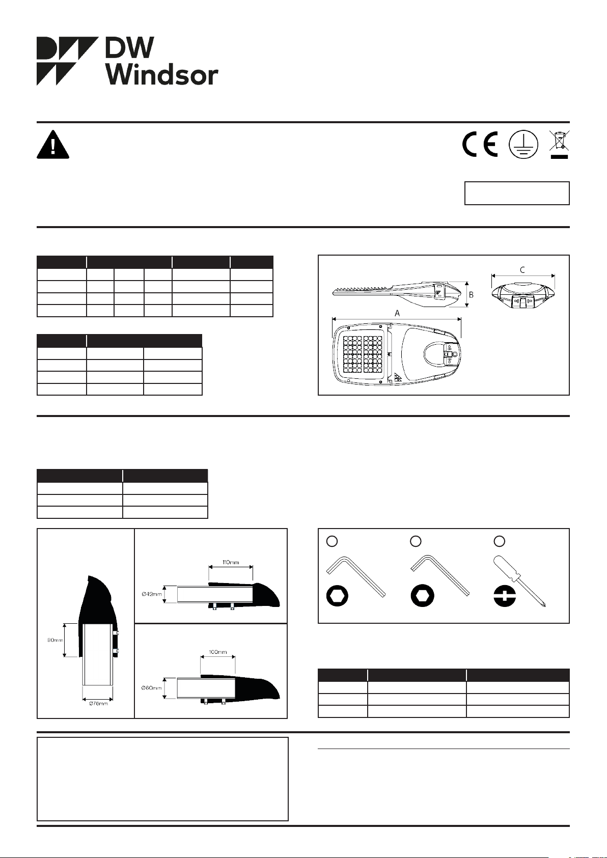
Product Details
The Kirium Pro range is supplied with entry detached from the luminaire.
Dimensions (mm) Max. Weight (kg)* Windage m²
A B C
Kirium Pro 1 610 140 350 8.5 0.048
Kirium Pro 2 720 140 350 9.8 0.0 52
Kirium Pro 3 1010 167 415 17.1 00.867
*Maximum weight of lantern including post top entry.
Power Ranges (Watts)
Standard CLO Enabled
Kirium Pro 1 7-105 6-95
Kirium Pro 2 22-198 20-177
Kirium Pro 3 41-394 37-353
Fig. 1 - Kirium Pro 2 (Please See Kirium Pro data sheet for all Kirium Pro technical drawings).
Column Engagement Fasteners Supplied
The information shown below details the length of column engagement for
each entry option.
Entry Options Column Engagement
76mm Post Top Entry 80mm
42mm Side Entry 110mm
60mm Post Top and Side Entry 100mm
• 2x M10 Screw
• 4x Disc Spring Washer
• 2x M10 Grub Screw
• 2x Locking Nut (for Kirium Pro 2 and 3 only, when using a Side Entry)
Tools Required
Tools not supplied.
230VAC 50Hz
Fig. 1
76mm Post Top 42mm Side Entry
60mm Post Top and Side Entry
Fig. 2 - Length of column engagement for each entry option.
NOTE!
• Luminaire to be positioned so that prolonged staring into the
luminaire at distances closer than shown below is not expected.
• Do not stare at operating light source.
• Personnel to wear Protective Safety Glasses compliant with EN166 1F/ EN169 5 when commissioning or maintaining this luminaire.
•
o Kirium Pro1 - 3.4m
o Kirium Pro2 - 4.8m
o Kirium Pro3 - 6.6m
Fig. 2
Sheet 1 of 4
8mm Allen Key1
Fig. 3 - Kirium Pro 2 (Please See Kirium Pro data sheet for all Kirium Pro technical drawings).
5mm Allen Key2
Pozi or Slotted
3
Screwdriver
Fig. 3
Recommended Torque
Entry Mounting Torque (Nm) Column Mounting Torque (Nm)
Kirium Pro 1 30 16
Kirium Pro 2 30 16
Kirium Pro 3 30 16
Kirium® Pro is a registered design.
Due to continuous product development the details within this document
are subject to change at any time, please contact us for the most up-to-date
information or visit: www.dwwindsor.com
DW Windsor
Pindar Road, Hoddesdon, Hertfordshire, EN11 ODX
T: +44 (0) 1992 474600 | E: info@dwwindsor.com
dwwindsor.com
50264-004 - 10/630/01
Kirium Pro Installation Steps | Post Top Entry
The Kirium Pro Range
LED Road Light
Kirium Pro 1, 2 and 3
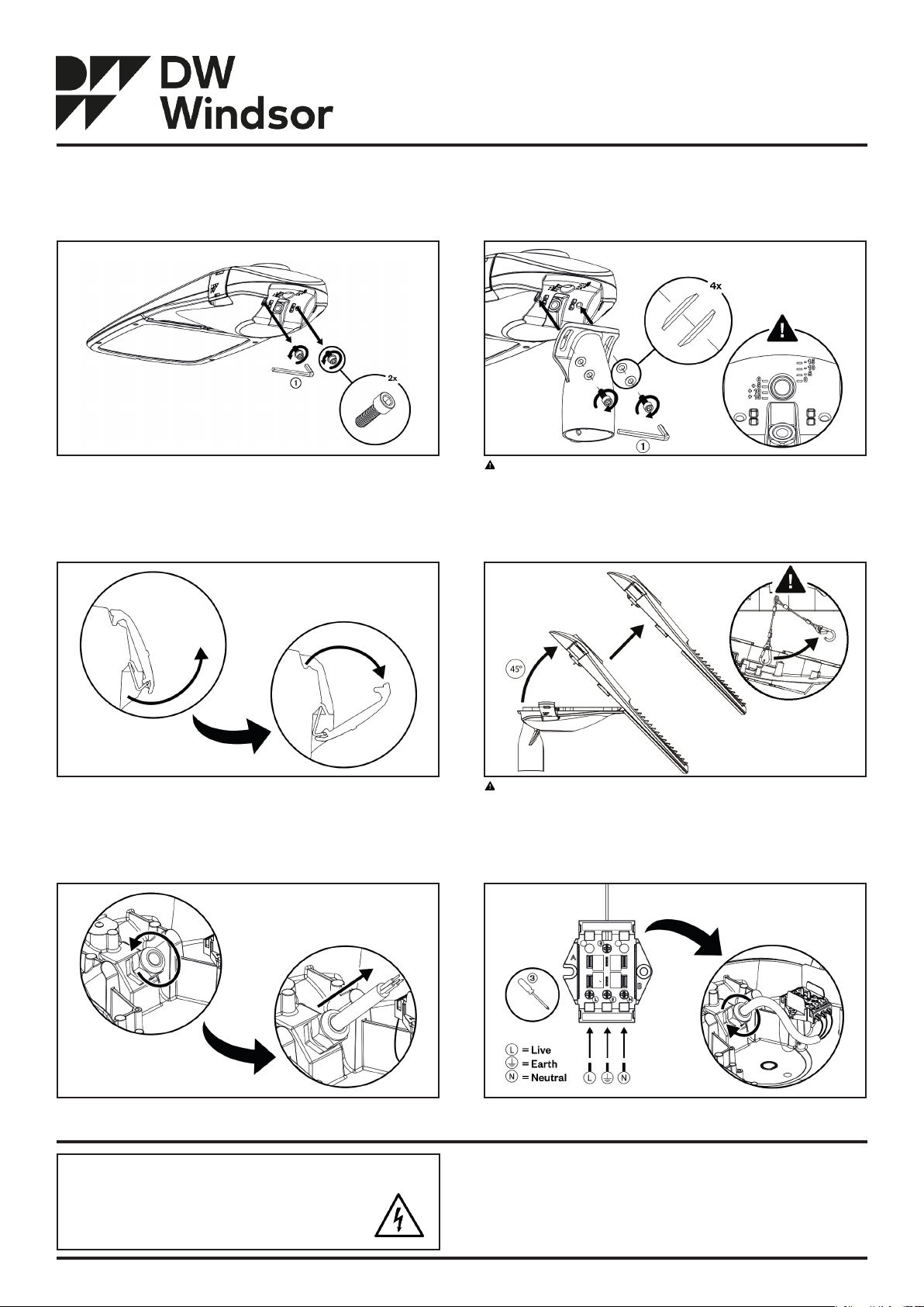
Step 1
Loosen and remove pre-attached 2x M10 screws and 4x disc spring washers
from luminaire with 8mm allen key.
Step 3
Undo quick-release side latches, and leave latches in open position.
Step 2 (See Step 2A for Side Entry installation instructions)
Fit entry to luminaire with supplied fasteners, tightening to 30Nm torque. 4x
Disc spring washers must be installed in the correct orientation.
Ensure entry is aligned to desired mounting angle.
Step 4
Pivot lift-off head 45° away from base and remove. Store lift-off head in safe
area during base installation.
Step 5
Loosen cable gland cap within base and feed through cable tail.
NOTE!
• LEDs contained within this luminaire shall only be replaced by the
manufacturer, their service agent or similar qualified person.
• The Live Supply is insulated (single) from the DALI conductor.
Undo safety wire before removal of lift-off head. Ensure lift-off head is
fully constrained at all times during removal. Kirium Pro 3 Only.
Step 6
Wire cable to electrical disconnect with Pozi or Slotted Screwdriver. Tighten
gland cap to 6Nm torque to ensure IP sealing is maintained.
DW Windsor
Pindar Road, Hoddesdon, Hertfordshire, EN11 ODX
T: +44 (0) 1992 474600 | E: info@dwwindsor.com
dwwindsor.com
Sheet 2 of 4
50264-004 - 10/630/01
Kirium Pro Installation Steps | Post Top Entry
The Kirium Pro Range
LED Road Light
Kirium Pro 1, 2 and 3
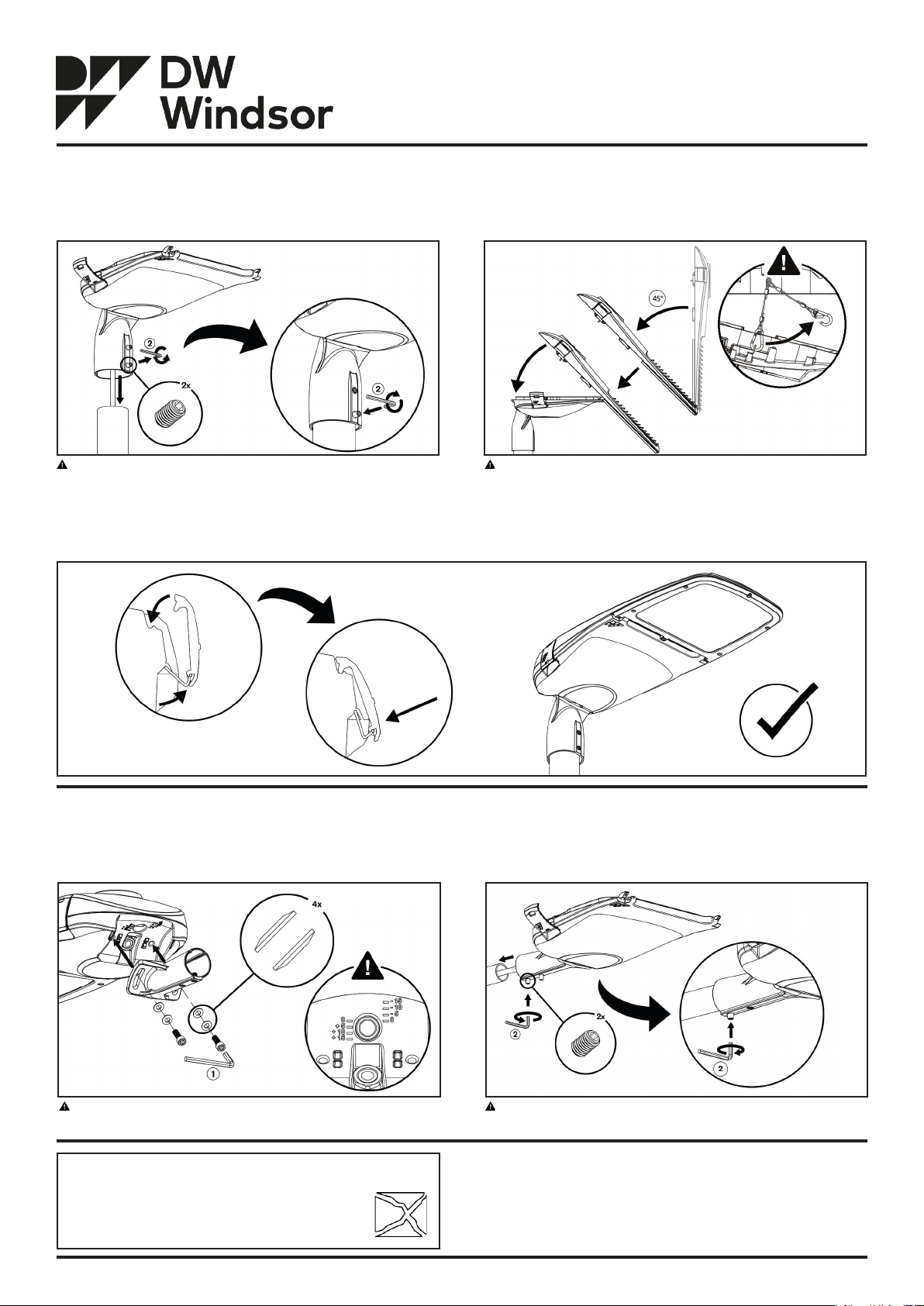
Step 7 (See Step 7A for Side Entry installation instructions)
Loosen 2x M10 grub screws on entry with 5mm allen key. Slide entry on to
column (See column engagement table). Tighten grubs screws to 16Nm.
Align luminaire with area to be illuminated.
Step 9 (See Step 9A for Side Entry installation instructions)
Close luminaire and fasten quick-release side latches.
Step 8
Angle lift-off head 45° and fit to base ensuring both pivot points are fully
engaged.
CRITICAL! Attach safety wire to lift-off head before closing luminaire.
Kirium Pro 3 Only.
Kirium Pro Installation Steps | Side Entry
Step 2A
Fit entry to luminaire with supplied fasteners, tightening to 30Nm torque. 4x
Disc spring washers must be installed in the correct orientation.
Ensure entry is aligned to desired mounting angle.
NOTE!
LEDs contained within this luminaire shall only be replaced
by the manufacturer, their service agent or similar qualified
person.
Step 7A
Loosen 2x M10 grub screws on entry with 5mm allen key. Slide entry on to
column (See column engagement table). Tighten grubs screws to 16Nm.
Align luminaire with area to be illuminated.
DW Windsor
Pindar Road, Hoddesdon, Hertfordshire, EN11 ODX
T: +44 (0) 1992 474600 | E: info@dwwindsor.com
dwwindsor.com
Sheet 3 of 4
50264-004 - 10/630/01
Kirium Pro Installation Steps | Side Entry
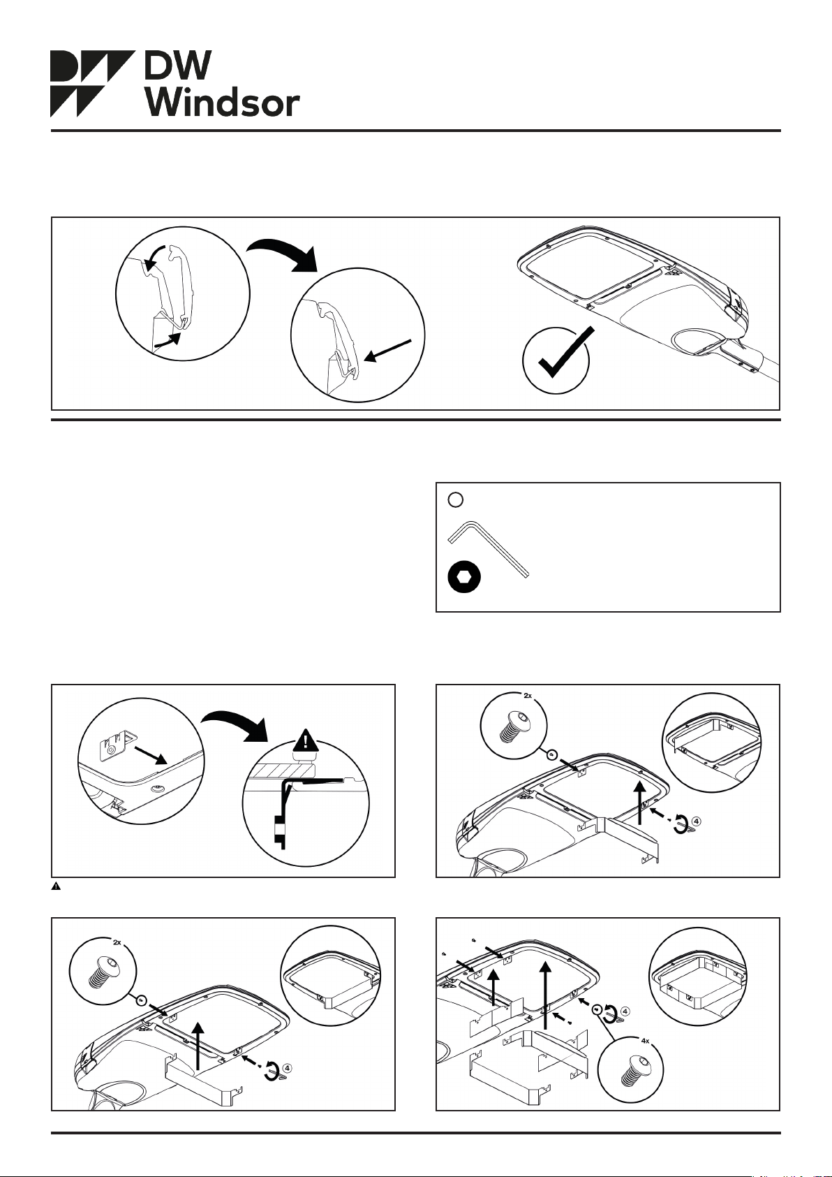
Step 9A
Close luminaire and fasten quick-release side latches.
The Kirium Pro Range
LED Road Light
Kirium Pro 1, 2 and 3
Anti-Glare Shield
Anti-Glare Shields can be fitted to the luminaire post-installation, without
opening the product.
Fasteners Supplied
Spring Clips and M4 screws are supplied in the following quantities for each
anti-glare shield option.
• 2x for Front Shields
• 2x for Back Shields
• 4x for Front & Back Shields (6x for Front & Back Shields on Kirium Pro 3)
Spring Clips
Fit spring clips to luminaire before attaching anti-glare shields. Spring clips are
push-fit and non-removeable once fitted.
Tools Required
Tools not supplied.
2.5mm Allen Key4
Fig. 4
Fig. 4 - Tools required for Kirium Pro Anti-Glare Shield installation. Not supplied.
Ensure Anti-Glare Shield Clips are securely attached to the luminaire.
Fig. 6 - Kirium Pro back anti-glare shield installation.
Fig. 5 - Kirium Pro front anti-glare shield installation.
Fig. 7 - Kirium Pro full anti-glare shield installation.
Sheet 4 of 4
Fig. 5
Fig. 7Fig. 6
50264-004 - 10/630/01
 Loading...