

DWIN TV 3 Plus User Manual

™
TransVision
3 Enhanced
TransVision™ 3 Enhanced
1.1
Printed in USA


Table of Contents
Safety Instructions .......................................................................................... 2
Introduction ..................................................................................................... 5
Processor Front Panel Controls ..................................................................... 6
Processor Rear Panel—Connections and Installation .................................. 7
Programming URC-100 Remote Control to Operate TransVision™ 3E ...... 11
Quick Reference Remote Control Operation .............................................. 12
Navigating The Control Menus ...................................................................14
Information Menu ..................................................................................... 14
Main Menu ............................................................................................... 14
Input Option. ............................................................................................15
Format Option .......................................................................................... 15
Video Control Menu .................................................................................16
Setup Options ..........................................................................................17
Menu Timeout ................................................................................. 17
Menu Position .................................................................................. 17
Rename Inputs ................................................................................18
Rename Formats ............................................................................. 18
Num Buttons ...................................................................................19
Screen Setup ................................................................................... 19
Image Setup ....................................................................................19
Custom Format ................................................................................ 20
Relay Setup ...................................................................................... 21
Power Button Setup ........................................................................ 21
Lamp Hours ..................................................................................... 21
Projector Installation ...................................................................................22
Physical Dimensions ...................................................................................31
TransVision™ 3E RS-232 Control .................................................................32
Specifications ............................................................................................... 33
Warranty . ...................................................................................................... 35
1
Safety Instructions
WARNING
HAZARDOUS VOLTAGE
DO NOT OPEN
ATTENTION
COURANT ELECTRIQUE
NE PAS OUYRIR
CAN SHOCK, BURN OR CAUSE SEVERE INJURY OR DEATH. DO NOT
REMOVE THE TOP COVER. REFER SERVICING TO QUALIFIED PERSONNEL.
!
.
1. Read and apply all of the safety and operating instructions with your
video equipment.
2. Keep all safety and operating instruction for future reference.
3. Unplug this video equipment from the wall outlet before cleaning. Never
use liquid or aerosol cleaners. Use only a damp cloth for cleaning.
4. Do not use any attachments or accessories not recommended by the
manufacturer as they may cause hazards.
5. Do not use this video equipment near water. Avoid placing it near a
bathtub, kitchen sink, or laundry tub, in a wet basement, or near a swim
ming pool.
6. Do not place this video equipment on an unstable cart, stand, or table.
The video equipment may fall, causing serious injury to a child or adult
and serious damage to the appliance. Use only with a cart or stand rec
ommended by the manufacturer. Wall or shelf mounting should follow
the manufacturer’s instructions, and should use a mounting kit approved
by the manufacturer.
6.1 Move any appliance and cart combination with care. Quick stops,
excessive force, and uneven surfaces may cause the appliance and a
cart to overturn.
7. Side, Top and Bottom openings in the cabinet are provided for ventila-
tion, and to insure reliable operation of the video equipment and protect
it from overheating. These openings must not be blocked or covered.
Never place the video equipment on a bed, sofa, rug, or other similar
surface that may block ventilation openings. Never place this product
near or over a radiator or heat register. Do not place this product in a
built-in installation such as a bookcase or rack unless proper ventilation
is provided.
8. Operate only from the type of power source indicated on the marking
label. If you are not sure of the type of power supply to your home, con
sult your appliance dealer or local power company.
9. This unit is equipped with a three conductor polarized alternating-current
line plug. This plug will fit into the power outlet only one way. This is a
safety feature. If you are unable to insert the plug fully into the outlet,
contact your electrician to replace your obsolete outlet. Do not defeat
-
-
-
2

the safety purpose of the polar-ized plug.
10. Route power supply cords so that they will not be walked on or pinched
by items placed on or against them. Pay particular attention to cords
at plugs, convenience receptacles, and the points where they exit the
products.
11. Protect your video equipment from lightning during a storm or when it
is left unattended and unused for long periods of time, unplug it from
the wall outlet. This will prevent damage to the unit due to lightning
and power-line surges.
12. Do not overload wall outlets and extension cords as this can result in
fire or electric shock.
13. Never push objects of any kind into this video equipment through cabi-
net slots as they may touch dangerous voltage points or short out parts
that could results in a fire or electric shock. Never spill liquid of any kind
on the video equipment.
14. Do not attempt to service this unit yourself as opening or removing cover may
expose you to dangerous voltages or other hazards. Refer all servicing to
qualified service personnel.
15. Unplug this video equipment from the wall outlet, and refer servicing
to quali-fied service personnel under the following conditions:
15.1 When the power cord or plug is damaged or frayed.
15.2 If liquid has been spilled into the video equipment.
15.3 If the video equipment has been exposed to rain or water.
15.4 If the video equipment does not operate normally by following the
operating instructions.
15.5 Adjust only those controls that are covered by the operating instructions
as improper adjustment of other controls may result in damage and
will often require extensive work by a qualified technician to restore
the video equipment to normal operation.
15.6 If the video equipment has been dropped or the cabinet has been
damaged.
15.7 When the video equipment exhibits a distinct change in perfor-
mance.
16. When replacement parts are required, be sure the service technician
has used replacement parts specified by the manufacturer that have the
same characteristics as the original part. Unauthorized substitutions
may result in fire, electric shock, or other hazards.
17. Upon completion of any service or repairs to this video equipment, ask
the service technician to perform routine safety checks to determine
that the sys-tem is in safe operating condition.
18. Do not place anything on the video equipment. Heavy objects placed
on any part of this system will cause damage.
19. WARNING: To prevent fire or shock hazard, do not expose this appliance
to rain or moisture. To prevent electric shock do not use this (polarized)
plug with an extension cord, receptacle or other outlet unless the blades
can be fully inserted to prevent blade exposure.
3

NOTE: This equipment is designed to operate in the USA, Canada and other
countries where the broadcasting system and AC house current is exactly
the same as in the USA and Canada.
IMPORTANT INFORMATION FOR THE USER/FCC STATEMENT
This equipment has been tested and found to comply with the limits for a
Class B digital device, pursuant to Part 15 of the FCC Rules. The limits are
designed to provide reasonable protection against harmful interference in a
commercial environment. This equipment generates, uses and can radiate
radio frequency energy and, if not installed and used in accordance with
the instructions, may cause harmful interference to radio communication.
However, there is no guarantee that harmful interference will not occur in
a particular installation. If this equipment does cause harmful interference
to radio or television reception, which can be determined by turning the
equipment off and on, the user is encouraged to try to correct the interfer
ence by one or more of the following measures:
• Reorient or relocate the receiving antenna.
• Increase the separation between the equipment and receiver.
• Connect the equipment into an outlet on a circuit different from that to
which the receiver is connected.
• Consult the dealer or and experienced radio/TV technician for help.
-
4

Introduction
TransVision™ 3 Enhanced(3E) is a High Definition Digital Video Projection system comprising of two complementary components: a High Definition Video
Projector featuring Dark Chip
from Texas Instruments and a Digital Video Processor. The TransVision
offers an outstanding progressive scan HDTV images with 16:9 aspect ratio
and 1280 x 720 (720P) native resolution.
The TransVision
™
Projector may be floor or ceiling mounted and configured
for front or rear projection.
The Digital Video Processor is designed to be located at the video sources.
It accepts a total of 10 video inputs, provides source switching, digital video
processing of analog and digital video sources and delivers a 720p digital
output to the Projector via a proprietary DVI cable.
The ten video inputs include: two HDCP compliant DVI-D; two RGB; two
Component Video; two S-Video and two Composite.
Signal connections between the Digital Video Processor and the Projector
are made through a proprietary DVI cable with a Control Signal. The Control
Signal is used to transmit bi-directional control signals (on, off, lamp status…)
between the Projector and the Processor.
An infrared learning wireless remote control with on-screen graphics selects
the input source and adjusts all of the operating controls. The system may also
be controlled from the front panel or from a RS-232 serial port.
IR sensors on both the Projector and the Processor allow the system to be
controlled from either unit.
Video and image settings for each individual video input may be adjusted
and stored separately in the system’s memory. These settings are recalled for
each input and video type when selected.
The TransVision
™
3E determines the video signal type by measuring horizontal and vertical scanning frequencies. If the video signal matches a predefined
video source, the TransVision
system’s memory. The predefined video sources include: 480i, 480p, 580i, 580p,
1080i, 540p, and 720p and computer sources VGA, SVGA, XGA, SXGA.
In addition to predefined video sources, the TransVision
to create up to three new video source memory locations per video input.
For more details on how to create memory location for new video sources
refer to the “Image Setup Menu.
Two programmable 12 Volt screen trigger outputs are also provided to trig
ger a relay in an electric screen, projector lift, or other relay activated device.
™
3 Digital Light Processing (DLP™) technology
™
™
3E selects video and image settings from the
™
3E allows the user
”
3E
-
5

Processor Front Panel Controls
The TransVision™ 3E Processor front panel controls include:
POWER button to turn the system On or Off.
• A
• An indicator light (LED) which is lit when the unit is turned on and blinks when
a valid IR command is received.
— When the LED is DARK the AC power to the unit is turned off.
— When the LED is flashing On and Off, power is connected and the unit is
in the standby mode.
— When the LED is on the unit is powered on.
— When the LED is flashing fast, this indicates that the lamp failed to ignite.
If the lamp failed to ignite, the lamp may either be burned or hot. In case
the lamp is hot, wait approximately 1 minute to turn the unit on.
IR Receiver Window
• An
• A MENU button to display the Main menu or to return to the previous
menu.
•
Up ▲ and down ▼ FUNCTION buttons to sequences through the on-screen
menu options.
• Left
◀ and right ▶ VALUE buttons to adjust values or to move to a sub-
menu.
6

Processor Rear Panel — Connections and Installation
1 9
2
3
5
6
7
8
4
1. DVI/HDCP Output to Display DVI-D
2. DVI/HDCP Inputs (DVI 1, DVI 2) DVI-D
3. Switched +12 VDC Outputs (RY1, RY2) 2.5mm DC Plug
4. RGBS Computer/HDTV Inputs (RGB1, RGB2) D-sub 15 pin Socket
5. RS-232 Computer Input (RS-232) D-sub 9 pin Socket
6. S-Video Inputs (S1, S2) 4 pin Mini-Din
7. Composite Video Inputs (V1, V2) RCA Type
8. Component Video Inputs (Y1, R1, B1) RCA Type
(Y2, R2, B2) RCA Type
9. AC Power Receptacle (AC IN) 3 Prong Receptacle
7
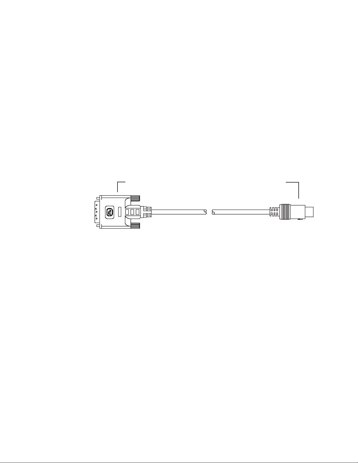
1. DIGITAL OUTPUT (DVI )
Connect the digital video output from the processor to the projector using
DWIN’s DVI-D cable.
Special Note about In-Wall Installations and Cable Lengths:
A standard rectangular DVI connector is fairly large in size (approximately 2”
wide) making it difficult to run through the walls. DWIN’s solution is to termi
nate one end of the DVI cable with a .75” circular connector that can easily run
through a 1” conduit (figure 1).
DWIN offers a series of unique (DVI-D-xx) cables in six different lengths: 25,
30, 35, 40, 45, and 50 feet. Part numbers for these cables are DVI-D-xx, the “xx”
refers to the length of the cable. Part numbers for these cables are DVI-D-xx,
the “xx” refers to the length of the cable. For cable lengths longer than 50 feet,
use DWIN’s Cable Extender. The cable extender operates with DVI-R-xx cables
and are available in 25, 35, and 50 Feet lengths
Connects to the Processor Connects to the Projector
-
Fig. 1: DVI Cable with Circular Connector
2. DVI-D INPUTS
The DVI 1 and DVI 2 inputs are HDCP compliant for High-Definition (480p,
580p, 720p, 1080i) sources or computer graphics with VGA, SVGA, XGA, and
WXGA resolutions. For computer graphics with VGA, SVGA, XGA, or WXGA
it is recommended to set the computer to 60 Hz vertical frequency.
If your computer video card has DVI output, connect the DVI cable to the DVI
1 or DVI 2 inputs of the Digital Processor. Select the corresponding DVI input by
pressing “9” or “0” on the remote control, then activate the DVI output from
the computer by using computer’s display set-up menu.
8

The following are the pin assignments for the DVI-D connectors:
Pin No. Signal Name Pin No. Signal Name Pin No. Signal Name
1 Data 2- 10 Data 1+ 18 Data 0+
2 Data 2+ 11 Data 1 / Shield 19 Data 0 / Shield
3 Data 2 / Shield 14 +5V Power 22 Clock Shield
6 DDC Clock 15 Ground 23 Clock+
7 DDC Data 16 Hot Plug Detect 24 Clock-
9 Data 1- 17 Data 0-
3. SWITCHED +12 VDC OUTPUTS
The TransVision
™
3E Processor has two switched +12 VDC outlets (2.5 mm DC
plug) labeled as RY1 and RY2. These outlets may be used to trigger a relay in
an electric device. Each output provides 100 ma DC current. See Relay Setup
menu for more details.
4. RGB INPUTS
The RGBS1 and RGBS2 inputs (D-sub 15) are provided for High-Definition (480p,
580p, 720p, 1080i) sources and computer graphics with VGA, SVGA, XGA, and
WXGA resolution. For computer graphics with VGA, SVGA, XGA, or WXGA it
is recommended to set the computer to 60 Hz vertical frequency.
The following are the pin assignments for the D-sub 15 pin connector:
Pin No. Signal Name Pin No. Signal Name Pin No. Signal Name
1 Red 6 Ground 11
2 Green 7 Ground 12
3 Blue 8 Ground 13 Horz. SYNC
4 9 Ground 14 Vert. SYNC
5 10 15
5. RS-232 COMPUTER INPUT
The RS-232C serial interface is provided for external control of the TransVision
™
3E from a central controller, such as a Home Theater control computer, Smart
Home automation system, etc.
For D-sub 9 pin connector pin-out and RS-232 command list, please refer
to “TransVision
™
3E RS-232 Control” section.
6. S-VIDEO INPUTS (S1, S2)
The S1 and S2 inputs are provided for NTSC (480i) or PAL (580i) video sources,
such as off-air tuners, satellite systems, cable boxes, SVHS VCR and DVD play
ers. S-Video inputs, instead of composite video inputs, are recommended for
use with DVD players and satellite systems.
-
9

7. COMPOSITE VIDEO INPUTS (V1, V2)
The V1 and V2 inputs are provided for NTSC (480i) or PAL (580i) video sources,
such as off-air tuners, satellite systems, cable boxes, VCR and DVD players.
8. COMPONENT VIDEO INPUTS (Y1, Y2, Y3)
Two component video Y, Cr, Cb or Y, Pr, Pb inputs are provided for interlaced
video signals from regular DVD players (480i, 580i), progressive component
video signals from progressive DVD players (480p, 580p), and progressive or
interlaced HD signals (480p, 540p, 720p, 1080i) from HD sources. The TransVi
sion™ 3E Processor automatically detects the resolution and configuration of
the component video signal applied to its input and processes it accordingly.
9. AC POWER RECEPTACLE
The AC power receptacle should be connected to a non-switched 120 VAC outlet
™
using the power cord provided with the TransVision
DWIN strongly recommends that the TransVision
3E system.
™
3E Projector and Processor both be connected to the same AC line circuit using a high quality surge
protector or power line conditioner.
-
10
 Loading...