

Dwin Plasmaimage HD-250, Plasmaimage HD-242 User Manual

Plasmaimage
HD-242, HD-250
™
Plasmaimage
2.4
Printed In USA
™


Table of Contents
Safety Instructions .......................................................................................... 2
Cautions ...........................................................................................................4
Introduction ..................................................................................................... 5
Front Panel Controls ....................................................................................... 6
Processor Rear Panel—Connections and Installation ..................................7
Programming URC-100 Remote Control to Operate Plasmaimage™ .......11
Quick Reference Remote Control Operation .............................................. 12
Navigating The Control Menus ...................................................................14
Information Menu ..................................................................................... 14
Main Menu ...............................................................................................14
Input Option. ............................................................................................15
Format Option .......................................................................................... 15
Video Control Menu .................................................................................16
Setup Menu .............................................................................................. 17
Menu Timeout ................................................................................. 18
Screen Saver .................................................................................... 18
Sidebars ...........................................................................................18
Num Buttons ...................................................................................19
Menu Position .................................................................................. 19
Rename Inputs ................................................................................19
Rename Formats ............................................................................. 20
Image Setup ....................................................................................20
Custom Format ................................................................................ 22
Relay Setup ..................................................................................... 22
Plasmaimage™ RS-232 Control ................................................................... 23
Plasma Display Specifications .................................................................... 24
Video Processor Specifications .................................................................. 25
Warranty . ...................................................................................................... 26
1
1. Read and apply all of the safety and operating instructions with your
WARNING
HAZARDOUS VOLTAGE
DO NOT OPEN
ATTENTION
COURANT ELECTRIQUE
NE PAS OUYRIR
CAN SHOCK, BURN OR CAUSE SEVERE INJURY OR DEATH. DO NOT
REMOVE THE TOP COVER. REFER SERVICING TO QUALIFIED PERSONNEL.
!
.
video equipment.
2. Keep all safety and operating instructions for future reference.
3. Unplug this video equipment from the wall outlet before cleaning. Never
use liquid or aerosol cleaners. Use only a damp cloth for cleaning.
4. Do not use any attachments or accessories not recommended by the manufacturer as they may cause hazards.
5. Do not use this video equipment near water. Avoid placing it near a bathtub,
kitchen sink, laundry tub, in a wet basement, or near a swimming pool.
6. Do not place this video equipment on an unstable cart, stand, or table. The
video equipment may fall, causing serious injury to a child or adult and serious
damage to the appliance. Use only with a cart or stand recommended by the
manufacturer. Wall or shelf mounting should follow the manufacturer’s instructions, and should use a mounting kit approved by the manufacturer.
6.1 Move any appliance and cart combination with care. Quick stops, ex-
cessive force, and uneven surfaces may cause the appliance and a cart to
overturn.
7. Side, Top and Bottom openings in the cabinet are provided for ventilation,
and to insure reliable operation of the video equipment and protect it from
overheating. These openings must not be blocked or covered. Never place
the video equipment on a bed, sofa, rug, or other similar surface that may
block ventilation openings. Never place this product near or over a radiator
or heat register. Do not place this product in a built-in installation such as
a bookcase or rack unless proper ventilation is provided.
8. Operate only from the type of power source indicated on the marking label.
If you are not sure of the type of power supply to your home, consult your
appliance dealer or local power company.
9. This unit is equipped with a three conductor polarized alternating-current
line plug. This plug will fit into the power outlet only one way. This is a safety
feature. If you are unable to insert the plug fully into the outlet, contact your
electrician to replace your obsolete outlet. Do not defeat the safety purpose
of the polarized plug.
10. Route power-supply cords so that they will not be walked on or pinched by
items placed on or against them. Pay particular attention to cords at plugs,
convenience receptacles, and the points where they exit the products.
Safety Instructions
2

11. To protect your video equipment from lightning during a storm or when
it is left unattended and unused for long periods of time, unplug it from
the wall outlet. This will prevent damage to the unit due to lightning and
power-line surges.
12. Do not overload wall outlets and extension cords as this can result in fire
or electric shock.
13. Never push objects of any kind into this video equipment through cabinet
slots as they may touch dangerous voltage points or short out parts that
could results in a fire or electric shock. Never spill liquid of any kind on the
video equipment.
14. Do not attempt to service this unit yourself as opening or removing cover
may expose you to dangerous voltages or other hazards. Refer all servicing to
qualified service personnel.
15. Unplug this video equipment from the wall outlet, and refer servicing to
qualified service personnel under the following conditions:
15.1 When the power cord or plug is damaged or frayed.
15.2 If liquid has been spilled into the video equipment.
15.3 If the video equipment has been exposed to rain or water.
15.4 If the video equipment does not operate normally by following the
operating instructions.
15.5 Adjust only those controls that are covered by the operating instructions
as improper adjustment of other controls may result in damage and
will often require extensive work by a qualified technician to restore
the video equipment to normal operation.
15.6 If the video equipment has been dropped or the cabinet has been
damaged.
15.7 When the video equipment exhibits a distinct change in perfor-
mance.
16. When replacement parts are required, be sure the service technician has
used replacement parts specified by the manufacturer that have the same
characteristics as the original part. Unauthorized substitutions may result
in fire, electric shock, or other hazards.
17. Upon completion of any service or repairs to this video equipment, ask the
service technician to perform routine safety checks to determine that the
system is in safe operating condition.
18. Do not place anything on the video equipment. Heavy objects placed on
any part of this system will cause damage.
19. WARNING: To prevent fire or shock hazard, do not expose this appliance
to rain or moisture. To prevent electric shock do not use this (polarized)
plug with an extension cord, receptacle or other outlet unless the blades
can be fully inserted to prevent blade exposure.
NOTE: This equipment is designed to operate in the USA, Canada and other
countries where the broadcasting system and AC house current is exactly the
same as in the USA and Canada.
3

IMPORTANT INFORMATION FOR THE USER/FCC STATEMENT
This equipment has been tested and found to comply with the limits for a Class
B digital device, pursuant to Part 15 of the FCC Rules. The limits are designed
to provide reasonable protection against harmful interference in a commercial
environment. This equipment generates, uses and can radiate radio frequency
energy and, if not installed and used in accordance with the instructions,
may cause harmful interference to radio communication. However, there is
no guarantee that harmful interference will not occur in a particular installation. If this equipment does cause harmful interference to radio or television
reception, which can be determined by turning the equipment off and on, the
user is encouraged to try to correct the interference by one or more of the
following measures:
• Reorient or relocate the receiving antenna.
• Increase the separation between the equipment and receiver.
• Connect the equipment into an outlet on a circuit different from that to which
the receiver is connected.
• Consult the dealer or and experienced radio/TV technician for help.
Cautions Regarding Phosphor Burn
DWIN is not responsible for any phosphor burn. Phosphor burn is not covered
by the warranty.
As with all phosphor-based display devices and other plasma displays, plasma
monitors can be susceptible to a condition called phosphor burn under certain
conditions. Phosphor burn describes a condition when latent images remain on
the screen even when the original signal is not displayed. The condition may
occur in any display using phosphors (CRT projectors, direct view monitors,
plasma screens).
The condition is most likely to occur when displaying a static image (e.g.,
news channel, stock market ticker, DVD menu screens, video games) for long
periods of time.
To protect your investment in your DWIN Plasmaimage™, DWIN recommends
the following guidelines to minimize the possibility of phosphor burn:
1. Display only moving images.
2. Avoid displaying fixed images for prolonged periods of time (no more than
five minutes).
3. Display 16:9 (wide screen) video sources.
4. View 4:3 video sources only with the Sidebars option On.
5. Change the position of the menu display from time to time.
6. Always power off your Plasmaimage™ when you are finished viewing.
™
7. Use the DWIN Motion Adaptive
at all times.
Screen Saver mode and Sidebars option
4

Introduction
DWIN’s Plasmaimage™ HD system comprises two complementary components: DWIN’s acclaimed Digital Video Processor and a high-definition
plasma monitor. The HD-242 plasma display has a native resolution of
1024 x 768 pixels. The HD-250 display has a native resolution of 1366 x 768
pixels. Unless otherwise noted, this manual describes the function of both
plasma models.
The Digital Video Processor consolidates and switches up to 10 video
inputs: two HDCP compliant DVI-D; two RGB; two Component Video; two
S-Video and two composite signals. Six sources support HDTV/digital signals. The processor provides both source switching and superior digital
video processing of both analog and digital video sources, delivering the
full native resolution of the panel, regardless of the input video source.
This unique separate component design provides flexible connectivity
by allowing the Digital Video Processor to be conveniently located near all
the video sources while the Plasma Display is mounted on a wall or table
top/counter for an ideal viewing position. Only a single cable is needed to
connect the plasma to view up to 10 different video input sources.
Signal connections between the Digital Video Processor and the Plasma
Display are uncompressed and remain purely digital for optimal picture
quality. The cable includes a bi-directional communication link between
two units used to transmit signals (on, off, display status...) between the
Plasma Display and the Processor. The DVI cable must be connected to
both units to power up1.
The Digital Video Processor is controlled via an infrared (IR) remote that
operates on-screen graphics to select the input source and adjust all picture
controls. The system may also be controlled from the front panel or from
an RS-232 serial port.
The Digital Video Processor automatically senses the video signal type
by measuring both horizontal and vertical scanning frequencies. If the
video signal matches a predefined video source, the Processor then recalls
a predefined setting from the system’s memory. Predefined video sources
include: 480i, 480p, 580i, 580p, 1080i, 540p, and 720p. A variety of computer
sources are also supported including: VGA, SVGA, XGA and SXGA.
Settings for each input video signal can then be adjusted and stored
separately in the system’s memory. These settings are automatically recalled
for each input and video type when selected.
Two programmable +12 Volt DC outputs are also provided to trigger
relay-activated electronic devices.
1. Please note: All functions for the Plasmaimage™ HD Series (including on/off) are automati-
cally controlled via the separate Digital Video Processor or remote control. As a result, all
non-DVI inputs and control buttons (located on the front panel) are disabled in HD-Series
display.
5

Processor Front Panel Controls
The Plasmaimage™ Processor front panel controls include:
• A
POWER button to turn the system On or Off.
• An indicator light (
a valid IR command is received.
— When the LED is dark the AC power to the unit is turned off.
— When the LED is flashing, power is connected and the unit is in the standby
mode.
• An IR Receiver Window
MENU button to display the Main menu or to return to the previous
• A
menu.
LED) which is lit when the unit is turned on and blinks when
•
Up ▲ or down ▼ FUNCTION buttons to sequences through the on-screen
menu options.
•
Left ◀ or right ▶ VALUE buttons to adjust values or to move to a sub-menu.
Plasma Display Front Panel Controls
Please note: All functions for the Plasmaimage™ HD Series (including on/off)
are automatically controlled via the separate Digital Video Processor or remote
control. As a result, all non-DVI inputs and control buttons (located on the
front panel) are disabled in HD-Series plasma displays.
• To power up the plasma display, the DVI cable MUST first be connected to
the Digital Video Processor.
• The plasma display has a master power switch, located next to the AC Power
input.
• After connecting both the AC power and DVI cable, turn the master power
switch to place the plasma display in standby mode
— When the LED is DARK the AC plug is not connected or the master power
switch is off.
— When the LED is Amber, the plasma display is in standby mode.
— When the LED is GREEN, the display is ON.
6
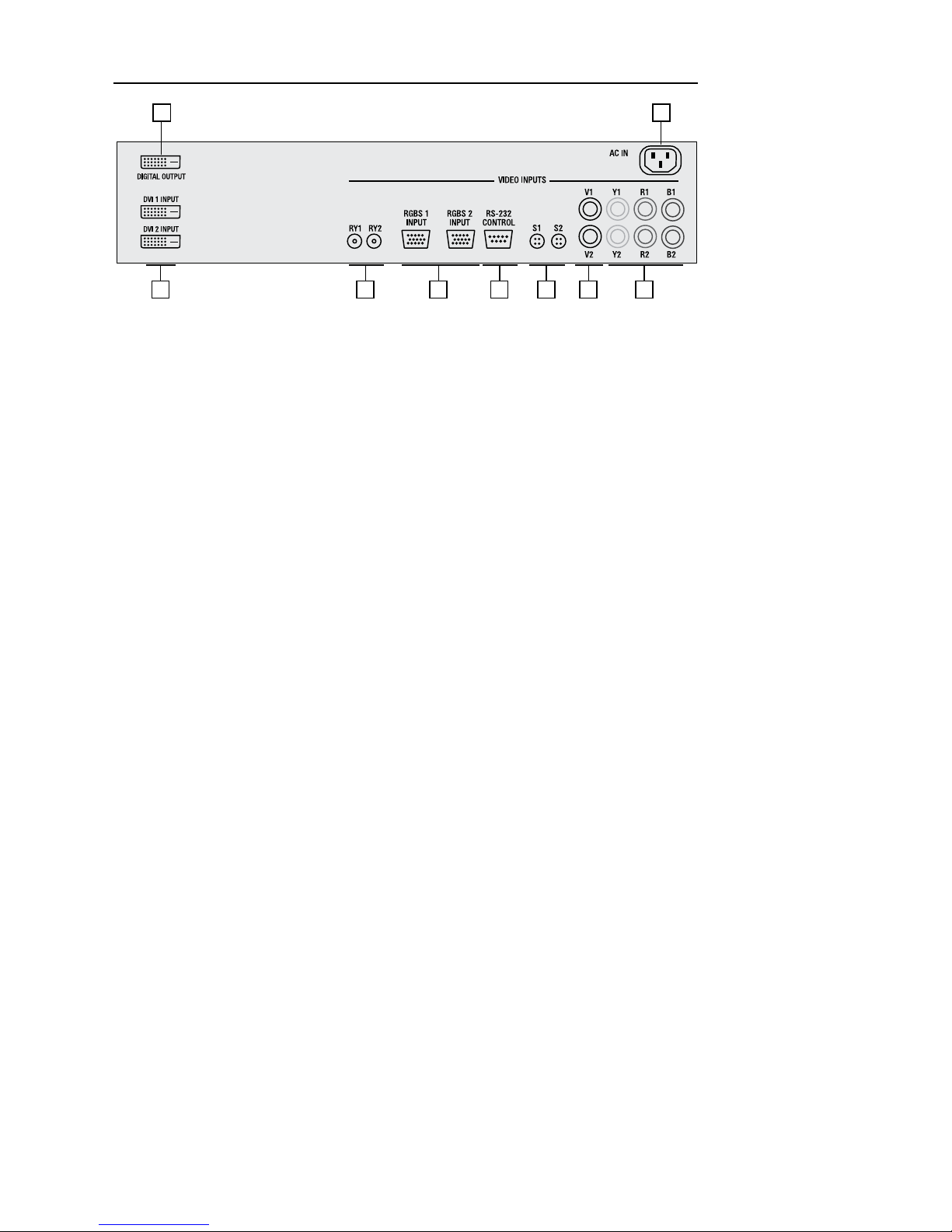
Processor Rear Panel — Connections and Installation
1 9
2
3
5
6
7
8
4
1. DVI/HDCP Output to Display DVI-D
2. DVI/HDCP Inputs (DVI 1, DVI 2) DVI-D
3. Switched +12 VDC Outputs (RY1, RY2) 2.5mm DC Plug
4. RGBS Computer/HDTV Inputs (RGB1, RGB2) D-sub 15 pin Socket
5. RS-232 Computer Input (RS-232) D-sub 9 pin Socket
6. S-Video Inputs (S1, S2) 4 pin Mini-Din
7. Composite Video Inputs (V1, V2) RCA Type
8. Component Video Inputs (Y1, R1, B1) RCA Type
(Y2, R2, B2) RCA Type
9. AC Power Receptacle (AC IN) 3 Prong Receptacle
7
 Loading...