

Dwin HDP-500 Installation And Operating Instructions Manual

HDP-500 SUPERDATA
PROJECTION MONITOR
Installation and Operating Instructions
Read these instructions completely before operating this unit.
Contents subject to change without notice or obligation.
Printed in USA
HDP-500
Safety Information ___________
Important Information for the User___________________
Specifications ___________
Introduction ___________
Pre Installation Preparations________________________7
Signal Connections___________________________________7
Front Panel Connections __________ ______
Preparation for Adjustment___________________________9
Remote Control Operation __________
Initial Set Up and Adjustment_______________________11
Focus Adjust Menu ________________
Geometry Adjust Menu ________________
Convergence Adjustments ________________
Gray Scale Adjustment ________________
Brightness Adjustment ________________
Contrast Adjustment __________
Center Convergence __________
Centering Adjustments ________________
Blanking Adjustments __________
Size Adjustments ________________
Source Memory Entry __________
Global Setup Adjustments __________
Power On Control ________________
Menu Access ________________
Menu time-out __________
White Balance Control __________
Scan Reversal __________
Screen Size Change Procedures ________________
Service & Warranty__________________________________
Table of Contents
3
4
5
6
8
10
11
13
17
20
21
21
21
21
22
22
22
23
23
23
24
24
25
27
29
CAN SHOCK, BURN OR CAUSE SEVERE INJURY OR DEATH. DO NOT
REMOVE COVER OR BACK PANEL. REFER SERVICING TO QUALIFIED PERSONNEL.
DWIN Electronics, Inc.
5838 San Fernando Road Unit D
Glendale, CA 91202
Tel: 818-956-1608
Fax: 818-956-0721
WARNING
HAZARDOUS VOLTAGE
DO NOT OPEN
ATTENTION
COURANT ELECTRIQUE
NE PAS OUYRIR
This manual and all information pertaining to circuit
designs, internal operating software and industrial
design are Copyright © by DWIN Electronics Inc.
All Rights Reserved.
Any reproduction or distribution is strictly prohibited.
2 of 29
!
.

SAFETY INFORMATION
1. Read and apply all of the safety and operating instructions provided with your video
equipment.
2. Keep all safety and operating instruction for future reference.
3. Unplug this video equipment from the wall outlet before cleaning. Never use liquid or
aerosol cleaners. Use only a damp cloth for cleaning.
4. Do not use any attachments or accessories not recommended by the manufacturer as
they may cause hazards.
5. Do not use this video equipment near water. Avoid placing it near a bathtub, kitchen sink,
or laundry tub, in a wet basement, or near a swimming pool.
6. Do not place this video equipment on an unstable cart, stand, or table. The video
equipment may fall, causing serious injury to a child or adult and serious damage to the
appliance. Use only with a cart or stand recommended by the manufacturer. Wall or shelf
mounting should follow the manufacturer's instructions, and should use a mounting kit
approved by the manufacturer.
Move any appliance and cart combination with care. Quick stops, excessive force, and
uneven surfaces may cause the appliance and a cart to overturn.
7. Top and bottom openings in the cabinet are provided for ventilation, and to insure reliable
operation of the video equipment and protect it from overheating. These openings must
not be blocked or covered. Never place the video equipment on a bed, sofa, rug, or other
similar surface that may block ventilation openings. Never place this product near or over
a radiator or heat register. Do not place this product in a built-in installation such as a
bookcase or rack unless proper ventilation is provided.
8. Operate only from the type of power source indicated on the marking label. If you are not
sure of the type of power supply to your home, consult your appliance dealer or local
power company.
9. This unit is equipped with a three conductor polarized alternating-current line plug. This
plug will fit into the power outlet only one way. This is a safety feature. If you are unable
to insert the plug fully into the outlet, contact your electrician to replace your obsolete
outlet. Do not defeat the safety purpose of the polarized plug.
10. Route power-supply cords so that they will not be walked on or pinched by items placed
on or against them. Pay particular attention to cords at plugs, convenience receptacles,
and the points where they exit the products.
11. Protect your video equipment from lightning during a storm or when it is left unattended
and unused for long periods of time, unplug it from the wall outlet. This will prevent
damage to the unit due to lightning and power-line surges.
12. Do not overload wall outlets and extension cords as this can result in fire or electric
shock.
13. Never push objects of any kind into this video equipment through cabinet slots as they
may touch dangerous voltage points or short out parts that could result in a fire or electric
shock. Never spill liquid of any kind on the video equipment.
14. Do not attempt to service this unit yourself as opening or removing cover may expose you
to dangerous voltages or other hazards. Refer all servicing to qualified service
personnel.
15. Unplug this video equipment from the wall outlet, and refer servicing to qualified service
personnel under the following conditions:
a. When the power cord or plug is damaged or frayed.
b. If liquid has been spilled into the video equipment.
c. If the video equipment has been exposed to rain or water.
d. If the video equipment does not operate normally by following the operating
instructions. Adjust only those controls that are covered by the operating instructions
as improper adjustment of other controls may result in damage and will often require
3 of 29

extensive work by a qualified technician to restore the video equipment to normal
operation.
e. If the video equipment has been dropped or the cabinet has been damaged.
f. When the video equipment exhibits a distinct change in performance.
16.When replacement parts are required, be sure the service technician has used
replacement parts specified by the manufacturer that have the same characteristics as
the original part. Unauthorized substitutions may result in fire, electric shock, or other
hazards.
17. Upon completion of any service or repairs to this video equipment, ask the service
technician to perform routine safety checks to determine that the system is in safe
operating condition.
18. Do not place anything on the video equipment. Heavy objects placed on any part of this
system will cause damage.
19. WARNING: To prevent fire or shock hazard, do not expose this appliance to rain or
moisture.
20. CAUTION: TO PREVENT ELECTRIC SHOCK DO NOT USE THIS (POLARIZED) PLUG
WITH AN EXTENSION CORD, RECEPTACLE OR OTHER OUTLET UNLESS THE
BLADES CAN BE FULLY INSERTED TO PREVENT BLADE EXPOSURE.
NOTE: This equipment is designed to operate in countries where the AC Mains power
is 117 volts. Use with other AC voltages will cause serious damage to the unit and
may present a safety hazard. If you are in doubt as to the line current in your area,
please check with your installer before operating the projector.
MPORTANT INFORMATION FOR THE USER
I
Note: This equipment has been tested and found to comply with the limits for a Class B
digital device, pursuant to Part 15 of the FCC Rules. The limits are designed to provide
reasonable protection against harmful interference in a residential installation. This
equipment generates, uses and can radiate radio frequency energy and, if not installed and
used in accordance with the instructions, may cause harmful interference to radio
communication. However, there is no guarantee that harmful interference will not occur in a
particular installation. If this equipment does cause harmful interference to radio or
television reception, which can be determined by turning the equipment off and on, the user
is encouraged to try to correct the interference by one or more of the following measures:
• Reorient or relocate the receiving antenna.
• Increase the separation between the equipment and receiver.
• Connect the equipment into an outlet on a circuit different from that to which the receiver
is connected.
• Consult the dealer or an experienced radio/TV technician for help.
This device complies with Part 15 of the FCC Rules. Operation is subject to the following
two conditions: ( 1 ) this device may not cause harmful interference, and
( 2 ) this device must accept interference received, including interference that may cause
undesired operation.
Note: Changes or modifications may cause this unit to fail to comply with Part 15 of the
FCC Rules and may void the user’s authority to operate the equipment.
DWIN HDP-500 DATA PROJECTION MONITOR
4 of 29

SPECIFICATIONS AND TECHNICAL DATA
System Description:
Red, Green, Blue three CRT/lens large screen refractive projection
system for video and data applications. Separate screen required.
Optics:
USPL high resolution HD-145 data grade lenses. F1.03, hybrid design, fully color
corrected.
CRT’s:
7” Magnetic focus, liquid cooled with anti-reflective coated faceplate.
5.6” active raster diagonal and 70 degree deflection angle.
Screen Size:
60 - 150 inch diagonal. Factory Preset for 100” diagonal.
Screen Configuration:
Front or rear through, floor or ceiling mounted.
Light Output:
1100 lumens (10% peak white)
Optical Resolution:
10 line pairs per mm, 1250 TV lines
Video Bandwidth:
75 MHz ( -3 dB) Pixel Resolution: 1280 x 1024
Input:
RGB - 0.7V p-p, 75 ohm positive (BNC)
H/V Sync - 0.7 - 4.0 V p-p, 75 ohm positive or negative. (BNC)
Convergence System:
Digital system with 60 preset memory positions. Static and dynamic
wave convergence via wireless remote or RS-232C port.
Convergence Accuracy:
Less than 0.2% of vertical height.
Test Patterns:
Cross Hatch, Cross Hair, Focus Dot, Window, H & E Patterns,
Gray Scale, Flat Field, Needle Pulse.
Scan Frequency:
Horizontal: 28 - 65 kHz. Vertical: 40 - 120 Hz
Retrace Time:
Horizontal - 3.5 uS Vertical: 450 uS
Data Communication Port:
Power Input:
100 - 130 / 200 - 250 VAC 50/60 Hz Power Consumption: 220 watts max.
Dimensions:
(H x W x D): 9.5” x 22” x 22.5”. Weight: 65 lbs/29.5 kg
Environment:
Operating Temperature: 10 to +35 deg. C Humidity: 0 - 90% non condensing
Storage: minus 10 to +50 deg. C.
Supplied Accessories:
Full function wireless remote, Ceiling Mount kit, Owner’s Manual &
Installation Manual, PC control software (3.5” disk).
RS-232C, sample software supplied. DB-9 connector.
Introduction
5 of 29

This manual contains the information required to properly install, configure, setup and operate the
DWIN HDP-500 data projection monitor. Please make certain that you fully read and understand the
information in this manual before proceeding with any installation.
THIS MANUAL CONTAINS IMPORTANT INSTRUCTIONS THAT WILL ASSURE A SAFE AND SUCCESSFUL
INSTALLATION. INSTALLING THE UNIT OTHER THAN AS DESCRIBED IN THIS MANUAL MAY LEAD TO
UNSAFE OPERATION AND/OR CONDITIONS WHICH MAY RESULT IN UNSATISFACTORY OPERATION
OR SHORTENED LIFE SPAN OF KEY COMPONENTS. INSTALLATIONS NOT COMPLYING WITH THESE
INSTRUCTIONS MAY ALSO RESULT IN CONDITIONS THAT VOID THE PRODUCT’S WARRANTY.
The HDP-500 is a totally new projector design, combining state of the art circuit components and
proprietary software that makes installation and operation easier than ever before. In order to take
advantage of this breakthrough product, it is helpful to consider the installation process as containing
five distinct steps. Carefully plan for each of them and your installation will proceed quickly and easily.
• Plan the physical aspects of the installation carefully. Use the DWIN’s HDP-500 Projection software to
make certain that the projector to screen distance is correct for the size and aspect ratio of the screen.
• Adjust the unit while it is easily accessible, BEFORE mounting it to a ceiling or placing it in the final
installation. Pre-setting the unit up to rough in adjustments for focus, screen size, geometry and
convergence will greatly speed your final installation. In addition, it is always easier to make mechanical
and electronic adjustments on the bench than it is on the ceiling! Don’t forget to make any needed
changes to set the unit for floor/ceiling or front/rear projection throw before the final installation!
• CAREFULLY AND SAFELY mount the unit. For ceiling mount installation, make certain that the
mounting hardware is properly secured to the structural frame. For floor or table mount installations, be
certain that the unit is mounted on a firm, level surface that can support the projector’s weight. Make
certain that all mounting surfaces are free from vibration and that adequate space is provided for
ventilation around the unit.
• Once the unit is set or installed in the actual viewing location, carefully follow the mechanical and
physical installation procedures.
• Finally, make certain that you explain all operating features of the projector to the owner and that any
possible compatibility issues with playback software and the chroma decoder, doubler or quadrupler, or
computer used with the projector are resolved.
Pre Installation Preparations
6 of 29

Planning a projection television installation is a critical part of the installation. Even with the extended range of
mechanical and electronic correction circuitry built into the HDP-500, incorrect physical placement of the projector
may place it outside the range of the circuits.
Using the HDP-500 Projection software provided by DWIN, enter the width of the screen, the aspect ratio and the
mounting position of the projector (ceiling, center of screen or floor). The program will automatically calculate the
correct distance from the screen to the projector. Make certain that you correctly plan the mounting position and
that the information obtained from the planning software is carefully transferred to the installation venue.
For Floor Mount Installations
Floor mount locations should be level and solid, with an unobstructed view of the screen. DO NOT place the
projector on carpeting or other materials that will interfere with the circulation of air into the ventilation holes at the
bottom of the unit. Also, be careful not to place the projector in a location that is in the direct flow of heating or
cooling vents or in a damp location.
For Center Screen Installations
Follow the same basic instructions as for Floor Mount locations. In addition, make certain that the mounting
location is capable of supporting the weight of the projector.
For Ceiling Mount Installations
Follow the instructions included with the ceiling mount hardware, making certain that the assembly is carefully
attached to structural beams capable of supporting the weight of the projector. Plan for connections to the
projector of AC power, RGBS connections from the signal source, and a DB-9 connection if the RS-232C port will
be used for external control. To insure freedom from power line interference, a separate and properly grounded
AC circuit should be provided. Avoid the use of circuits connected to mechanical equipment, as they may induce
noise in the video system.
We strongly recommend that these instructions be followed BEFORE final installation. However, if the projector is
already mounted in place, follow these steps to establish proper operating conditions.
When the unit is first received, verify that the carton does not show any signs that may indicate internal damage.
If damage is suspected, make a report to the freight carrier immediately, and follow their claim procedures. In
addition, please report any carrier damage to DWIN.
If there is no obvious sign of damage, carefully unpack the projector. Due to the weight of the unit two people
should lift the projector from the carton. Carefully place the unit in the location where it will be tested and inspect it
again for any signs of concealed damage that may have been incurred in shipping. Report any interior damage to
the freight carrier and to DWIN.
Before proceeding, you may wish to store the carton for future use should the unit require return to DWIN. If you
discard the carton and shipping material, please observe local recycling rules.
Pre Installation Adjustment and Set Up
Unpacking
The HDP-500 is an RGB/Sync monitor, which means that it requires an external, line doubler, line quadrupler, or
chroma decoder for video playback. A computer interface may be required for display of computer images.
Connect your video and/or data sources to the external interface or processor, and then connect the RGBS
outputs of the processor, doubler, quadrupler or interface to the signal and sync connections on the HDP-500’s
front panel.
If composite sync is used, connect it to the “H/C Sync” terminal. If separate horizontal and vertical sync are used,
make connections to the appropriate terminals. The HDP-500 will not operate with “sync on green”.
Connect the AC power cord to the front panel and to a wall mounted AC power outlet. The use of extension cords
is not recommended.
Signal Connections
Front Panel Connections
7 of 29
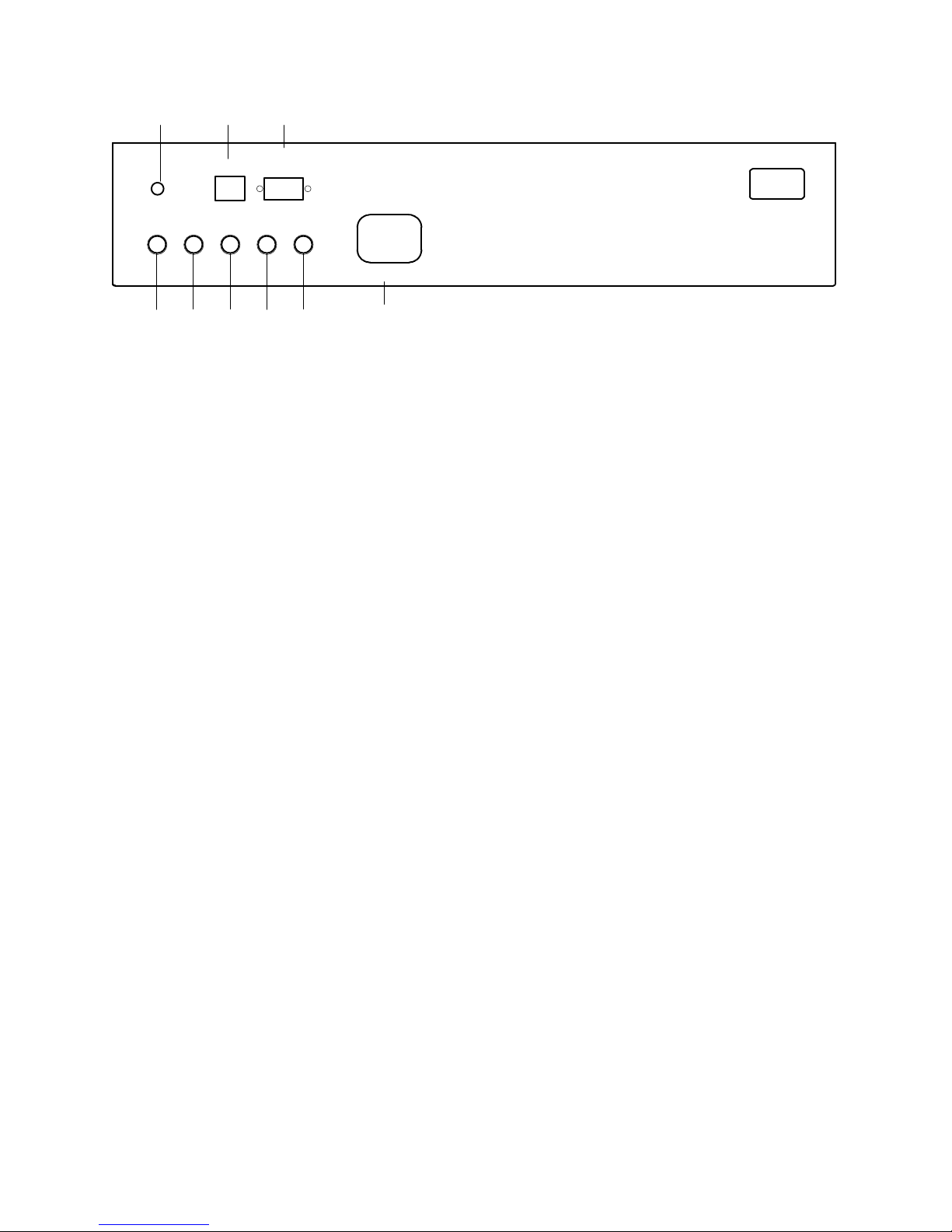
Make the appropriate connections to the front panel, using the following descriptions as a guide.
7 8 9
IR Input
RED GREEN BLUE
1 2 3 4 5 6
RS232C
Input
H/C V
SYNC SYNC
120VAC 60Hz
HDP-500
DWIN
1. Red Input: Connect the RED signal from the external decoder/processor to this jack.
2. Green Input: Connect the GREEN signal from the external decoder/processor to this jack.
3. Blue Input: Connect the BLUE signal from the external decoder/processor to this jack.
4. H/C Sync Input: When COMPOSITE SYNC is available, connect the feed from the external
decoder/processor to this terminal. If separate horizontal and vertical synch are present,
connect the HORIZONTAL SYNC feed to this jack.
5. Vertical Sync Input: If separate sync feeds are being used, connect the VERTICAL SYNC
feed to this jack.
6. AC Power Input: Connect the supplied AC power cord this receptacle.
7. The POWER LED is a multi-purpose indicator:
When the LED is dark the AC power to the unit is turned off.
When the LED is flashing on and off, power is connected to the unit, this indicates that
the unit is in the standby mode.
When the LED is on the unit is powered on.
NOTE: Depending on the configuration of the “Auto Power” the unit may be in a “Stand
By” mode, awaiting signal information. ALWAYS REMOVE THE AC POWER CORD TO
POSITIVELY TURN THE UNIT OFF BEFORE MAKING ANY INTERNAL ADJUSTMENTS.
8. IR Sensor: This window is the sensor for the HDP-500’s remote control system. For best
operation, make certain that the sensor has a direct view of the screen so that remote
commands made by pointing the control at the screen will be bounced back to the sensor. If the
sensor window is obstructed a remote IR extension system should be used.
9. RS232C Port: This DB-9 plug is used to operate the HDP-500 directly from a compatible
computer using the supplied software.
NOTE: THIS IS A DATA PORT ONLY. DO NOT MAKE ANY VIDEO SIGNAL CONNECTIONS
TO THIS INPUT!
Preparation for adjustment
8 of 29

Before initial adjustments are made to the unit, locate the correct distance from the
screen. This distance should be obtained by using the HDP-500 Projection software
supplied to you. Make certain that the front rubber feet are set so that the unit is level
and parallel to the floor. You may wish to verify this with a standard carpenter’s level.
In order to make certain adjustments, it is necessary to remove the unit’s cover.
First, loosen the screws at either side of the green (center) lens about 1/2” until the
cover panel pops up. It is not necessary to completely remove the screws. Next, push in
on the metal tabs at either end of the cover and gently pull the cover upward. While
holding the cover, pull it forward to remove it from the unit.
Remote Control Operation
The HDP-500 has no on board user controls. All operation is controlled through the wireless remote control or the
optional RS-232C link to a computer or control system.
9 of 29
 Loading...